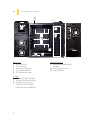
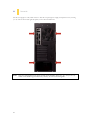
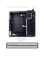
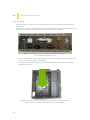
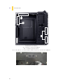
Antec DF-35 is a mid-tower gaming case with a matte black finish and a unique Fleet-Release system for quick access to drives. It features variable-speed 120 mm fans with white LEDs, two Fleet-Swap modular SATA interfaces, and a top-mounted 2.5” hot-swap bay for added convenience. With support for up to six 3.5” drives, three 5.25” drives, and two 2.5” drives, the DF-35 offers ample storage options for gamers and enthusiasts.
Antec DF-35 is a mid-tower gaming case with a matte black finish and a unique Fleet-Release system for quick access to drives. It features variable-speed 120 mm fans with white LEDs, two Fleet-Swap modular SATA interfaces, and a top-mounted 2.5” hot-swap bay for added convenience. With support for up to six 3.5” drives, three 5.25” drives, and two 2.5” drives, the DF-35 offers ample storage options for gamers and enthusiasts.


-
 1
1
-
 2
2
-
 3
3
-
 4
4
-
 5
5
-
 6
6
-
 7
7
-
 8
8
-
 9
9
-
 10
10
-
 11
11
-
 12
12
-
 13
13
-
 14
14
-
 15
15
-
 16
16
-
 17
17
-
 18
18
-
 19
19
-
 20
20
-
 21
21
-
 22
22
-
 23
23
-
 24
24
-
 25
25
-
 26
26
-
 27
27
-
 28
28
-
 29
29
-
 30
30
-
 31
31
-
 32
32
-
 33
33


Antec DF-35 is a mid-tower gaming case with a matte black finish and a unique Fleet-Release system for quick access to drives. It features variable-speed 120 mm fans with white LEDs, two Fleet-Swap modular SATA interfaces, and a top-mounted 2.5” hot-swap bay for added convenience. With support for up to six 3.5” drives, three 5.25” drives, and two 2.5” drives, the DF-35 offers ample storage options for gamers and enthusiasts.
Ask a question and I''ll find the answer in the document
Finding information in a document is now easier with AI
Related papers
Other documents
-
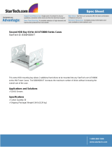 StarTech.com 8300HDDKIT Datasheet
-
Sharkoon 4044951014095 Datasheet
-
Rosewill R521-M Mini Tower Computer Case User manual
-
Gigabyte Sumo Alpha Specification
-
AIC RMC-2T Installation guide
-
 Casetek CK-1028-2B/W Datasheet
-
Akasa Crypto User manual
-
-
-
Black Box RMT078 Datasheet

