4
GB
PLEASE PHONE US TO REGISTER YOUR APPLIANCE AND ACTIVATE YOUR PARTS GUARANTEE ON 08448 24 24 24
Please read the precautions below before using your cooker.
ALWAYS . . .
ALWAYS make sure you understand the controls before using
the cooker.
ALWAYS check that all controls on the cooker are turned off after
use.
ALWAYS stand back when opening an oven door to allow heat to
disperse.
ALWAYS use dry, good quality oven gloves when removing items
from the ovens.
ALWAYS take care when removing items from the top oven/grill
when the main oven is on, as the contents may be hot.
ALWAYS keep the oven and grill doors closed when the cooker is
not in use.
ALWAYS place pans centrally over the hotplate burners and
position them so that the handles cannot accidentally be
caught or knocked or become heated by other burners.
ALWAYSALWAYS
ALWAYSALWAYS
ALWAYS
keep the cooker clean, as a build up of greasekeep the cooker clean, as a build up of grease
keep the cooker clean, as a build up of greasekeep the cooker clean, as a build up of grease
keep the cooker clean, as a build up of grease
or fat from cooking can cause a fire.or fat from cooking can cause a fire.
or fat from cooking can cause a fire.or fat from cooking can cause a fire.
or fat from cooking can cause a fire.
ALWAYS allow the cooker to cool before cleaning.
ALWAYS follow the basic principles of food handling and hygiene
to prevent the possibility of bacterial growth.
ALWAYS keep ventilation slots clear of obstructions.
ALWAYS turn off the electricity supply before cleaning or replacing
an oven lamp.
ALWAYS refer servicing to CORGI registered appliance service
engineers.
ALWAYS The appliance must be used by adults only for the
preparation of food, in accordance with the instructions
outlined in this booklet. Any other use of the appliance
(e.g. for heating the room) constitutes improper use
and is dangerous. The manufacturer may not be held
liable for any damage resulting from improper, incorrect
and unreasonable use of the appliance.
SAFETY ADVICE IN CASE OF A CHIP-PAN FIRE
In the event of a chip pan fire or any other pan fire.
1.TURN OFF THE COOKER APPLIANCE AT THE WALL SWITCH.
2.COVER THE PAN WITH A FIRE BLANKET OR DAMP CLOTH, this
will smother the flames and extinguish the fire.
3.LEAVE THE PAN TO COOL FOR AT LEAST 60 MINUTES
BEFORE MOVING IT. Injuries are often caused by picking up a hot
pan and rushing outside with it.
NEVER USE A FIRE EXTINGUISHER TO PUT OUT A PAN FIRE as
the force
of the extinguisher is likely to tip the pan over.
Never use water to extinguish oil or fat fires.
NEVER . . .
NEVER leave children unsupervised where the cooker is installed
as all surfaces will get hot during and after use.
NEVER allow anyone to sit or stand on any part of the cooker.
NEVER store items that children may attempt to reach above
the cooker.
NEVER heat up unopened food containers as pressure can
build up causing the container to burst.
NEVER store chemicals, food stuffs, pressurised containers in
or on the cooker, or in cabinets immediately above or
next to the cooker.
NEVER fill a deep fat frying pan more than 1/3 full of oil, and never
use a lid. DO NOT LEAVE UNATTENDED WHILE
COOKING.
NEVER place flammable or plastic items on or near the hotplate.
NEVER use proprietary spillage collectors on the hotplate.
NEVER use the cooker as a room heater.
NEVER dry clothes or place other times over or near to the
hotplate or oven/gril doors.
NEVER wear garments with long flowing sleeves whilst cooking.
NEVER
let children play with the appliance.
NEVER should the appliance be operated by people (including
children) with reduced physical, sensory or mental
capacities, by inexperienced individuals or by anyone
who is not familiar with the product. These individuals
should, at the very least, be supervised by someone
who assumes responsibility for their safety or receive
preliminary instructions relating to the operation of the
appliance.
NOTE:NOTE:
NOTE:NOTE:
NOTE: The use of a gas cooking appliance results in the production
of heat and moisture in the room in which it is installed. Always ensure
that the kitchen is well ventilated; keep natural ventilation holes open
or install a mechanical ventilation device (mechanical extractor hood).
In particular when using the grill or more than one hotplate burner,
open a window if a mechanical ventilation device is not operating.
!for their safety or receive preliminary instructions relating to the
operation of the appliance.
Safety Information
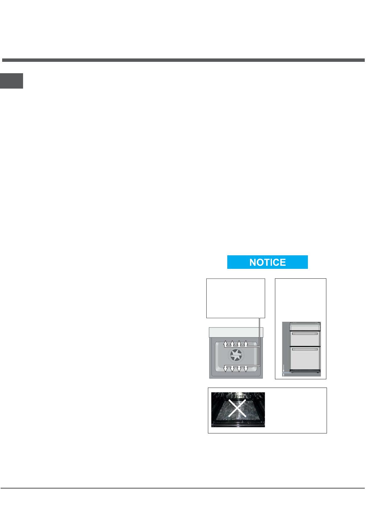
! ATTENTION
DURING INSTALLATION
THE FEET OF THE APPLIANCE
MUST BE LOWERED SO THAT
AN AIR GAP OF AT LEAST
10MM (1CM) IS LEFT BETWEEN
THE BASE OF THE APPLIANCE
AND THE FLOOR.
! VERY HOT SURFACES
YOU MUST KEEP THE OVEN
AND GRILL CAVITIES CLEAN
FOOD OR GREASE ON THESE
SURFACES COULD CAUSE
SMOKE AND POSSIBLY EVEN BURN
! ATTENTION
WHEN USING THE MAIN OVEN
YOU MUST ENSURE THAT THE
BASE OF THE CAVITY IS NOT
COVERED WITH ALUMINUM
FOIL, UTENSIL OR ANY OTHER
FORM OF COVERING. FAILURE
TO DO THIS MAY RESULT IN
THE CAVITY BEING DAMAGED.
10 mm
! ATTENTION! ATTENTION
! ATTENTION ! ATTENTION
! VERY HOT SURFACES! VERY HOT SURFACES


