Page is loading ...

Installation and User’s Guide
Adaptec SCSI Card 29320LPE

● 2
Copyright
©2006 Adaptec, Inc. All rights reserved. No part of this publication may be reproduced, stored in a retrieval system, or transmitted
in any form or by any means, electronic, mechanical, photocopying, recording or otherwise, without the prior written consent of
Adaptec, Inc., 691 South Milpitas Blvd., Milpitas, CA 95035.
Trademarks
Adaptec, SCSISelect and the Adaptec logo are trademarks of Adaptec, Inc., which may be registered in some jurisdictions.
Microsoft and Windows are trademarks of Microsoft Corporation in the US and other countries, used under license.
Red Hat is a trademark of Red Hat, Inc. in the US and other countries, used under license.
Novell and NetWare are trademarks of Novell, Inc. in the US and other countries, used under license.
All other trademarks are the property of their respective owners.
Changes
The material in this document is for information only and is subject to change without notice. While reasonable efforts have been
made in the preparation of this document to assure its accuracy, Adaptec, Inc. assumes no liability resulting from errors or
omissions in this document, or from the use of the information contained herein.
Adaptec reserves the right to make changes in the product design without reservation and without notification to its users.
Disclaimer
IF THIS PRODUCT DIRECTS YOU TO COPY MATERIALS, YOU MUST HAVE PERMISSION FROM THE COPYRIGHT
OWNER OF THE MATERIALS TO AVOID VIOLATING THE LAW WHICH COULD RESULT IN DAMAGES OR OTHER
REMEDIES.

● 3
Adaptec Customer Support
If you have questions about installing or using your Adaptec product, check this document first—you will find answers to most of
your questions. If you need further assistance, use the support options listed below. To expedite your service, have your system in
front of you.
Technical Support Identification (TSID) Number
● Before contacting Technical Support, you need your unique 12-digit TSID number. The TSID number identifies your product
and support status.
● The TSID number is included on a white, bar-coded label, like this example:
● Affix a copy of the TSID label to the CD jacket so that you don’t lose it.
North America
● Visit our Web site at www.adaptec.com.
● Search the Adaptec Support Knowledgebase (ASK) at ask.adaptec.com for articles, troubleshooting tips, and frequently asked
questions for your product.
●
For information about Adaptec’s support options, call +1 408-957-2550,
24 hours per day, 7 days per week. To speak with a Technical Support Specialist,
● For Hardware products call +1 408-934-7274,
Monday to Friday, 5:00
A.M. to 5:00 P.M., Pacific Time.
● For RAID and Fibre Channel products call +1 321-207-2000,
Monday to Friday, 5:00
A.M. to 5:00 P.M., Pacific Time.
● For support via e-mail, submit your question at ask.adaptec.com.
●
You can order Adaptec products, including accessories and cables, by calling +1 408-957-7274.
Or, you can order cables online at
www.adaptec.com/buy-cables.
Europe
● Visit our Web site at www.adaptec-europe.com.
● German: Call +49 89 43 66 55 22, Monday to Friday, 9:00 to 17:00, CET. For support via e-mail, submit your question at
ask-de.adaptec.com.
● French: Call +49 89 43 66 55 33, Monday to Friday, 9:00 to 17:00, CET. For support via e-mail, submit your question at
ask-fr.adaptec.com.
● English: Call +49 89 43 66 55 44, Monday to Friday, 9:00 to 17:00, GMT. For support via e-mail, submit your question at
ask.adaptec.com.
● You can order Adaptec cables online at www.adaptec.com/buy-cables.
Japan
● Visit our Web site at www.adaptec.co.jp.
● Call +81-3-3831-5190.

● 4
Limited 3-Year Hardware Warranty
1. Adaptec, Inc. (“Adaptec”) warrants to the purchaser of this product that it will be free from defects in material and workmanship
for a period of three (3) years from the date of purchase. If the product should become defective within the warranty period,
Adaptec, at its option, will repair or replace the product, or refund the purchaser’s purchase price for the product, provided it is
delivered at the purchaser’s expense to an authorized Adaptec service facility or to Adaptec.
2. Repair or replacement parts or products will be furnished on an exchange basis and will either be new or reconditioned. All
replaced parts or products shall become the property of Adaptec. This warranty shall not apply if the product has been damaged
by accident, misuse, abuse or as a result of unauthorized service or parts.
3. Warranty service is available to the purchaser by delivering the product during the warranty period to an authorized Adaptec
service facility or to Adaptec and providing proof of purchase price and date. The purchaser shall bear all shipping, packing and
insurance costs and all other costs, excluding labor and parts, necessary to effectuate repair, replacement or refund under this
warranty.
4. For more information on how to obtain warranty service, write or telephone Adaptec at 691 South Milpitas Boulevard,
Milpitas, CA 95035, (800) 959-7274.
5. THIS LIMITED WARRANTY DOES NOT EXTEND TO ANY PRODUCT WHICH HAS BEEN DAMAGED AS A RESULT OF
ACCIDENT, MISUSE, ABUSE, OR AS A RESULT OF UNAUTHORIZED SERVICE OR PARTS.
6. THIS WARRANTY IS IN LIEU OF ALL OTHER EXPRESS WARRANTIES WHICH NOW OR HEREAFTER MIGHT
OTHERWISE ARISE RESPECT TO THIS PRODUCT. IMPLIED WARRANTIES, INCLUDING THOSE OF
MERCHANTABILITY, FITNESS FOR A PARTICULAR PURPOSE AND NON-INFRINGEMENT SHALL (A) HAVE NO
GREATER DURATION THAN 3 YEARS FROM THE DATE OF PURCHASE, (B) TERMINATE AUTOMATICALLY AT THE
EXPIRATION OF SUCH PERIOD AND (C) TO THE EXTENT PERMITTED BY LAW BE EXCLUDED. IN THE EVENT THIS
PRODUCT BECOMES DEFECTIVE DURING THE WARRANTY PERIOD, THE PURCHASER’S EXCLUSIVE REMEDY
SHALL BE REPAIR, REPLACEMENT OR REFUND AS PROVIDED ABOVE. INCIDENTAL OR CONSEQUENTIAL
DAMAGES, INCLUDING WITHOUT LIMITATION LOSS OF DATA, ARISING FROM BREACH OF ANY EXPRESS OR
IMPLIED WARRANTY ARE NOT THE RESPONSIBILITY OF ADAPTEC AND, TO THE EXTENT PERMITTED BY LAW,
ARE HEREBY EXCLUDED BOTH FOR PROPERTY DAMAGE, AND TO THE EXTENT NOT UNCONSCIONABLE, FOR
PERSONAL INJURY DAMAGE.
7. SOME STATES DO NOT ALLOW THE EXCLUSION OR LIMITATION OF INCIDENTAL OR CONSEQUENTIAL DAMAGES
FOR CONSUMER PRODUCTS, AND SOME STATES DO NOT ALLOW LIMITATIONS ON HOW LONG AN IMPLIED
WARRANTY LASTS, SO THE ABOVE LIMITATION OR EXCLUSIONS MAY NOT APPLY TO YOU.
8. This warranty gives you specific legal rights, and you may also have other rights which vary from state to state.

● 5
Regulatory Compliance Statements
Federal Communications Commission Radio Frequency Interference Statement
WARNING: Changes or modifications to this unit not expressly approved by the party responsible for compliance could void the user’s authority to
operate the equipment.
This equipment has been tested and found to comply with the limits for a Class B digital device, pursuant to Part 15 of the FCC rules. These limits are
designed to provide reasonable protection against harmful interference in a residential installation. This equipment generates, uses, and can radiate
radio frequency energy, and if not installed and used in accordance with the instruction manual, may cause harmful interference to radio
communications. However, there is no guarantee that interference will not occur in a particular installation. However, if this equipment does cause
interference to radio or television equipment reception, which can be determined by turning the equipment off and on, the user is encouraged to try to
correct the interference by one or more of the following measures:
■ Reorient or relocate the receiving antenna.
■ Increase the separation between equipment and receiver.
■ Connect the equipment to an outlet on a circuit different from that to which the receiver is connected.
■ Consult the dealer or an experienced radio/television technician for help.
■ Use a shielded and properly grounded I/O cable and power cable to ensure compliance of this unit to the specified limits of the rules.
This device complies with part 15 of the FCC rules. Operation is subject to the following two conditions: (1) this device may not
cause harmful interference and (2) this device must accept any interference received, including interference that may cause
undesired operation.
European Union Compliance Statement
This Information Technology Equipment has been tested and found to comply with EMC Directive 89/336/EEC, as amended by 92/31/EEC
and 93/68/EEC, in accordance with:
● EN55022 (1998+A1:2000+A2:2003) Emissions
● EN55024 (1998+A1:2001+A2:2003) Immunity:
– EN61000-4-2 (1995) Electrostatic discharge: ±4 kV contact, ±8 kV air
– EN61000-4-3 (1996) Radiated immunity
– EN61000-4-4 (1995) Electrical fast transients/burst: ±1 kV AC, ±0.5 kV I/O
– EN61000-4-5 (1995) Surges ±1 kV differential mode, ±2 kV common mode
– EN61000-4-6 (1996) Conducted immunity: 3 V
– EN61000-4-11 (1994) Supply dips and variation: 30% and 100%
In addition, all equipment requiring U.L. listing has been found to comply with EMC Directive 73/23/EEC as amended by 93/68/EEC in
accordance with EN60950 with amendments A1, A2, A3, A4, A11.
Australian/New Zealand Compliance Statement
This device has been tested and found to comply with the limits for a Class B digital device, pursuant to the Australian/New Zealand standard
AS/NZS 3548 set out by the Spectrum Management Agency.
Canadian Compliance Statement
This Class B digital apparatus meets all requirements of the Canadian Interference-Causing Equipment Regulations.
Cet appareil numérique de la classe B respecte toutes les exigences du Règlement sur le matériel brouilleur du Canada.
Japanese Compliance (Voluntary Control Council Initiative)
This equipment complies to class B Information Technology equipment based on VCCI (Voluntary Control Council for Interface). This
equipment is designed for home use but it may causes radio frequency interference problem if used too near to a television or radio. Please
handle it correctly per this documentation.
Tested to Comply
With FCC Standards
FOR HOME OR OFFICE USE
ASC-29320LPE
Adaptec, Inc.

Contents
1 About This Guide
What You Need to Know Before You Begin ................................................... 10
Terminology Used in this Guide...................................................................... 10
How to Find More Information....................................................................... 10
2Kit Contents and
System Requirements
Kit Contents ...................................................................................................... 12
System Requirements........................................................................................ 12
3 About Your SCSI CARD
SCSI Card Features ........................................................................................... 14
About the Adaptec SCSI 29320LPE ................................................................. 14
4 Understanding SCSI
What is SCSI? .................................................................................................... 16
SCSI IDs............................................................................................................. 16
Terminating the SCSI Bus ................................................................................ 16
Using SCSI Devices ........................................................................................... 17
Using SCSI Disk Drives............................................................................ 17
Using Ultra320 and Ultra160 Disk Drives .............................................. 17
Using SCSI Devices .................................................................................. 18
Combining SCSI and Non-SCSI Devices ........................................................ 18
Installing Multiple SCSI Cards......................................................................... 18
Connecting the LED Connector.............................................................. 19
Overriding SCSI Termination Settings ............................................................ 19
Connecting SCSI Devices ................................................................................. 20
Adaptec SCSI Card 29320LPE ................................................................. 20
Maximum Cable Lengths ................................................................................. 21

Contents ● 7
5 Getting Started
Ultra320 SCSI on the Adaptec 29320LPE........................................................ 23
Device Drivers ................................................................................................... 23
Selecting Cables................................................................................................. 23
SCSI Cables............................................................................................... 23
Before You Begin............................................................................................... 24
Installing the Adaptec SCSI Card..................................................................... 24
Connecting Disk Drives.................................................................................... 24
Installing with an Operating System................................................................ 25
Installing on an Existing Operating System..................................................... 25
Uninstalling Your Adaptec 29320LPE ............................................................. 25
Replacing a SCSI Card ...................................................................................... 25
6 Installing the Driver and an Operating System
Before You Begin............................................................................................... 28
Creating a Driver Disk ...................................................................................... 28
Installing with Windows................................................................................... 28
Installing with Red Hat Linux .......................................................................... 29
Installing with SUSE Linux............................................................................... 29
Installing with NetWare.................................................................................... 29
7 Installing the Driver on an Existing Operating System
Before You Begin............................................................................................... 32
Creating a Driver Disk ...................................................................................... 32
Installing with Windows................................................................................... 32
Installing on Red Hat or SUSE Linux .............................................................. 33
Installing on NetWare....................................................................................... 33
8 Configuring the Adaptec SCSI Card with SCSISelect
Starting SCSISelect............................................................................................ 36
Exiting SCSISelect .................................................................................... 36
Using SCSISelect Settings ................................................................................. 36
SCSI Bus Interface Options ..................................................................... 36
Changing Configuration Settings............................................................ 39
Using SCSI Disk Utilities .................................................................................. 43
Listing SCSI IDs and LUNs...................................................................... 43
A Safety Information
Electrostatic Discharge (ESD) .......................................................................... 45

Contents ● 8
B Technical Specifications
Environmental Specifications........................................................................... 47
DC Power Requirements .................................................................................. 47
Current Requirements ...................................................................................... 47
C Using Advanced Configuration Parameters
Using Windows SCSI Parameters .................................................................... 49
Using Driver-specific Parameters..................................................................... 50
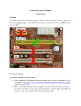
D Troubleshooting
Troubleshooting Checklist ............................................................................... 53
General Troubleshooting.................................................................................. 53
Troubleshooting Windows............................................................................... 54
Troubleshooting NetWare................................................................................ 54
Error Messages .................................................................................................. 56
Common Error Messages ........................................................................ 57
Driver Error Messages.............................................................................. 57
Windows Error Messages......................................................................... 59
Glossary
Index

1
About This Guide
In this chapter...
What You Need to Know Before You Begin .......................................................................... 10
Terminology Used in this Guide............................................................................................ 10
How to Find More Information ............................................................................................ 10
This Installation and User’s Guide provides information about using your Adaptec SCSI
29320LPE and SCSI devices, troubleshooting, SCSI termination, and a basic overview of SCSI
technology. It explains how to use the built-in SCSISelect® utility if you need to view or modify
your Adaptec SCSI card settings. It also explains how to install the software device drivers for
your operating system.

Chapter 1: About This Guide ● 10
What You Need to Know Before You Begin
You should be familiar with system hardware, data storage technology, and the input/output
(I/O) technology—SCSI—used by your card.
You should also be familiar with Direct Attached Storage (DAS) and Storage Area Network
(SAN) concepts and technology.
Terminology Used in this Guide
Because you can use your SCSI card to manage data storage in a variety of configurations from
DAS to SAN, the generic term “storage space” is used to refer to the disk drives and devices
being managed with SCSISelect described in this Guide.
Many of the terms and concepts referred to in this Guide are known to computer users by
multiple names. This Guide uses these terms:
● Card (also known as Host Bus Adapter, or board)
● Disk drive (also known as hard disk, hard drive, or hard disk drive)
● Device (also known as a printers, tape drives, and so on.)
How to Find More Information
You can find more information about your SCSI card and the software and utilities included
with it by referring to this document:
● Readme.txt—Includes updated product information and known issues; located on the
SCSI Installation CD.

2
Kit Contents and
System Requirements
In this chapter...
Kit Contents............................................................................................................................ 12
System Requirements .............................................................................................................12
This chapter lists the contents of your SCSI card kit and the system requirements that must be
met for you to successfully install and use your SCSI card.

Chapter 2: Kit Contents and System Requirements ● 12
Kit Contents
● Adaptec SCSI 29320LPE card with full-size bracket
● SCSISelect Utility (Embedded in the card’s BIOS)—Used to view and modify your SCSI
card and disk drive settings
● Installation CD
● Drivers for the Adaptec SCSI 29320LPE
● Product documentation for the Adaptec SCSI 29320LPE
● Readme Files
● 1 internal 68-pin high-density LVD cable with 6 positions and terminator
● Low-profile bracket
● Adaptec SCSI 29320LPE Quick Start Guide (printed)
System Requirements
● PC-compatible system with Intel Pentium, or equivalent, processor
● A motherboard with these features:
● Complies with the PCIe Local Bus Specification, Revision 1.0.
● One of these operating systems:
● Microsoft
®
Windows Server 2003, Windows XP
● Red Hat
®
Enterprise Linux 4.0
● SUSE Linux Enterprise Server 9.0, 10.0
Note:
For the latest on Adaptec’s support of Linux, or to download driver sources, visit the
Support area of the Adaptec Web site at
www.adaptec.com
.
● Novell
®
NetWare
®
6.5
● SCO
®
OpenServer
®
6.0
● UnixWare
®
● Sun
®
Solaris™ 10
● At least 256 MB (or more) of RAM
● Available compatible PCIe slot
● 40 MB of free drive space
● 16-bit SVGA color monitor with a resolution of at least 800 x 600
● CD drive
● SCSI interface cables

3
About Your SCSI CARD
In this chapter...
SCSI Card Features................................................................................................................. 14
About the Adaptec SCSI 29320LPE....................................................................................... 14
This chapter provides an overview of standard SCSI card features, and describes the unique
features of your SCSI card.

Chapter 3: About Your SCSI CARD ● 14
SCSI Card Features
● PCIe compatibility
● Programmable SCSI card BIOS ROM - 1 MB (Flash upgradeable)
● Support for LVD (Ultra320, Ultra160, or Ultra2) SCSI devices
About the Adaptec SCSI 29320LPE
The Adaptec 29320LPE is a low-profile single channel PCIe x1 Ultra320 SCSI card with these
features:
Form factor Low-profile
PCI compatibility PCIe x1
Channels Single
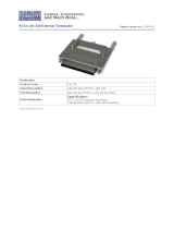
Connectors 1 internal 68-pin high density LVD connector
1 external VHDCI 68-pin LVD connector
Disk drives/Devices to 15
Active termination Yes
Programmable SCSI card BIOS ROM Yes
PCIe x1 connector
Mounting bracket
68-pin internal LVD connector
68-pin external LVD VHDCI connector
Activity
LED
Termination Enable jumper J4

4
Understanding SCSI
In this chapter...
What is SCSI?.......................................................................................................................... 16
SCSI IDs.................................................................................................................................. 16
Terminating the SCSI Bus...................................................................................................... 16
Using SCSI Devices ................................................................................................................ 17
Combining SCSI and Non-SCSI Devices.............................................................................. 18
Installing Multiple SCSI Cards .............................................................................................. 18
Overriding SCSI Termination Settings.................................................................................. 19
Connecting SCSI Devices....................................................................................................... 20
Maximum Cable Lengths....................................................................................................... 21
This chapter provides useful information on using the Adaptec SCSI Card and your SCSI
devices. For more information about a specific SCSI device, refer to the documentation for that
device.

Chapter 4: Understanding SCSI ● 16
What is SCSI?
SCSI (pronounced “scuzzy”) stands for Small Computer Systems Interface. SCSI is an industry
standard computer interface for connecting SCSI devices (such as a disk drive, CD-ROM drive,
or scanner) to a common SCSI bus.
A SCSI bus is an electrical pathway that consists of a SCSI card installed in a system and one or
more SCSI devices. SCSI cables are used to connect the devices to the SCSI card.
For the SCSI bus to function properly, a unique SCSI ID must be assigned to the SCSI card and
each SCSI device connected to it, and the SCSI bus must be properly terminated.
SCSI IDs
Each device attached to an Adaptec SCSI Card, as well as the Adaptec SCSI Card itself, must be
assigned a unique SCSI ID number from 0 to 15 for each of the two SCSI buses. A SCSI ID
uniquely identifies each SCSI device on the SCSI bus and determines priority when two or
more devices are trying to use the SCSI bus at the same time.
Refer to the device’s documentation to set the SCSI ID. Here are some general guidelines for
SCSI IDs:
● For internal SCSI devices, the SCSI ID is set by configuring a jumper on the device.
● For external SCSI devices, the SCSI ID is set with a switch on the back of the device.
● SCSI ID numbers do not need to be sequential, as long as the Adaptec SCSI Card and each
device has a different number. For example, on each of the two SCSI buses you can have an
internal SCSI device with ID 0, and an external SCSI device with ID 6.
● SCSI ID 7 has the highest priority on the SCSI bus. The priority of the remaining IDs are in
descending order: 6 to 0, then 15 to 8.
● The Adaptec SCSI Card is preset to SCSI ID 7 and should not be changed. This gives the
card the highest priority on the SCSI bus.
● Most internal SCSI disk drives come from the factory preset to SCSI ID 0.
● If you have 8-bit (or Narrow) SCSI devices, they must use SCSI IDs 0, 1, 2, 3, 4, 5, or 6.
SCSI ID 0 is recommended for the first SCSI disk drive.
● If you are booting your system from a SCSI disk drive connected to the Adaptec SCSI
Card, the Boot SCSI ID setting in the SCSISelect utility must correspond to the SCSI ID of
the device from which you are booting. By default, the Boot SCSI ID is set to 0. We
recommend that you do not change this setting.
● With the SCSISelect disk utility feature, you can confirm/view which SCSI ID is assigned to
each device. See Configuring the Adaptec SCSI Card with SCSISelect on page 34.
Terminating the SCSI Bus
To ensure reliable communication on the SCSI bus, the ends of the SCSI bus must be properly
terminated. This is accomplished when the device at the end of each cable, or the end of the
cable itself, has a terminator installed (or enabled). Terminators must be removed, or
termination must be disabled, on devices between the ends of each cable.

Chapter 4: Understanding SCSI ● 17
Since the method for terminating a SCSI device can vary widely, refer to the device’s
documentation for instructions on how to enable or disable termination. Here are some
general guidelines for termination:
● Internal Ultra320, Ultra160, and Ultra2 SCSI LVD devices come from the factory with
termination disabled and cannot be changed. Proper termination for these internal devices
is provided by the built-in terminator at the end of the 68-pin internal LVD SCSI cable.
● Termination on SE internal SCSI devices is usually controlled by manually setting a jumper
or a switch on the device, or by physically removing or installing one or more resistor
modules on the device.
● Termination on most external SCSI devices is controlled by installing or removing a SCSI
terminator. However, termination on some external SCSI devices is enabled or disabled by
setting a switch on the back of the SCSI device.
● By default, termination on an Adaptec SCSI Card itself is set to Automatic (the preferred
method). We recommend that you do not change this default setting. This automatic
setting is just for the Adaptec SCSI Card itself; the card cannot change the termination
setting on a device.
● Internal and external Ultra320, Ultra 160, and Ultra2 SCSI LVD SCSI buses must be
terminated with an LVD terminator. This is sometimes referred to as an LVD terminator or
a Multi-Mode terminator.
Using SCSI Devices
Using SCSI Disk Drives
If you connect a SCSI disk drive to an Adaptec SCSI card that was previously connected to a
different SCSI card, it is recommended that you low-level format the drive before you can use
it. Back up the data on the drive before moving the drive to the new SCSI card and before you
format the drive. (SeeUsing SCSI Disk Utilities
on page 43 for information on using the
SCSISelect format utility.)
Caution:
A low-level format destroys all data on the drive. Be sure to back up the data before
performing a low-level format.
Every SCSI disk drive must be physically low-level formatted, partitioned, and logically
formatted before it can be used to store data. For instructions on how to partition and format
your SCSI disk drives, refer to your operating system documentation.
Using Ultra320 and Ultra160 Disk Drives
Adaptec recommends that you connect your LVD (Ultra 320, Ultra160, and Ultra2) SCSI
devices to one SCSI Channel (bus) and your non-LVD SCSI devices (if any) to a separate SCSI
Channel (bus). This allows the LVD SCSI devices to run at their maximum performance levels
of 320 MB/sec, 160 MB/sec. or 80 MB/sec. If you combine LVD and non-LVD SCSI devices on
the same SCSI channel, the data transfer rate of the LVD SCSI devices will drop down to non-
LVD SCSI performance levels of up to 40 MB/sec.
Internal LVD SCSI devices come from the factory with termination disabled and cannot be
changed. Proper termination is provided by the terminator at the end of the internal LVD SCSI
cable.
!

Chapter 4: Understanding SCSI ● 18
Using SCSI Devices
If you connect SCSI devices (such as scanners, tape drives, zip drives, etc.) to your Adaptec
SCSI Card, you must install the device manufacturer’s proprietary software drivers. See your
device’s documentation for details.
Combining SCSI and Non-SCSI Devices
You can install an Adaptec SCSI Card in a system that already has a non-SCSI card, such as an
ATA, SATA, or Serial Attached SCSI (SAS) controller. However, you cannot cross-connect the
disk drives and other devices: SCSI devices must be connected to an Adaptec SCSI card, ATA
devices must be connected to the ATA controller, and so on.
When you install an Adaptec SCSI Card and SCSI disk drives in a system that boots from a
non-SCSI disk drive, the system will continue to boot from the non-SCSI disk drive unless you
change the system’s CMOS configuration. You do not need to change the configuration if you
just want to use the SCSI drives for additional file storage space.
If your system’s motherboard BIOS supports the BIOS Boot Specification (BBS) feature, you
can select a different boot device without much difficulty. (To determine if the motherboard
BIOS supports BBS, refer to the system documentation or contact your motherboard
manufacturer.)
After you install the SCSI card and SCSI devices to use different kinds of disk drives in the
same system, see the following table for recommendations.
Installing Multiple SCSI Cards
You can install multiple SCSI cards in your system; you are limited only by the available system
resources (for example, IRQ settings, I/O port addresses, BIOS addresses, and so forth).
Each SCSI card you install forms a separate SCSI bus with a different set of SCSI devices. SCSI
IDs can be reused as long as the ID is assigned to a device on a different SCSI card (for example,
each SCSI card can have a device with SCSI ID 2).
If you have two or more SCSI cards and your system boots from a SCSI disk drive, leave the
SCSI card BIOS enabled on the SCSI card to which the boot disk drive is connected. Use
SCSISelect to disable the SCSI card BIOS on the other SCSI cards.
Does computer BIOS
support BBS?
Want computer to boot
from SCSI drive? Then do this:
NO NO No action required. SCSI drives and non-SCSI
drives can be used together.
NO YES Run CMOS Setup program. Change primary
disk drive setting to None or No Drives
Installed (see system documentation). You
will not be able to use the non-SCSI drive(s) at
all when you boot from the SCSI drive.
YES NO No action required. SCSI drives and non-SCSI
drives can be used together.
YES YES Run CMOS Setup program and select SCSI
drive as boot device. SCSI drives and non-
SCSI drives can be used together.

Chapter 4: Understanding SCSI ● 19
If you have two or more SCSI cards, you can choose which SCSI card is found first by your
system by physically changing the order of the SCSI cards in the PCIe/PCI/PCI-X slots. Your
system scans the PCIe/PCI/PCI-X slots in a set order.
Connecting the LED Connector
(Optional feature) Most computers have an LED disk activity light on the front panel of the
system case. If you choose to disconnect the cable from the LED connector on the
motherboard and connect it to the LED connector on the SCSI card as shown in the figure
below, the LED on the front panel of the system will light whenever there is activity on the
SCSI bus.
Note:
If you connect the LED cable to the SCSI card, the LED disk activity light will no longer
indicate disk activity on the non-SCSI disk drives.
Overriding SCSI Termination Settings
You use SCSISelect to control the termination of the SCSI channel on an Adaptec SCSI Card.
The default termination setting for a channel is Automatic. This setting allows the SCSI card to
adjust SCSI termination automatically, depending on which connectors have SCSI devices
attached to them.
Regardless of the SCSISelect termination setting, the SCSI card termination is always disabled
when the power is turned off. If you want SCSI card termination to be enabled when the power
is turned off, you must terminate the SCSI channel manually.
To manually terminate the channel on the Adaptec SCSI 29320LPE, place a shunt on the
Termination enable jumper.The next figure shows where the jumper is located on Adaptec
SCSI 29320LPE.
LED Connector
on SCSI Card
1
LED Cable
from
Motherboard
Pin 1
1
2-pin
LED
Cable

Chapter 4: Understanding SCSI ● 20
If you manually terminate the SCSI card with jumpers, you will override the SCSISelect setting.
Making changes in SCSISelect will have no effect on termination when these jumpers are
installed.
You might want to manually terminate the SCSI card if an Adaptec SCSI Card is connected to
one or more external SCSI devices that are also connected to a SCSI card in another system.
The devices can be shared between the two computers if one SCSI card is terminated when it is
powered off, while the system with the other SCSI card is using the SCSI devices.
Connecting SCSI Devices
Here are some examples of how you can connect internal and external SCSI devices to an
Adaptec SCSI Card. Attach the first device to the end connector of the cable (furthest from the
SCSI card); attach other devices to the connectors that are closer to the SCSI card.
Adaptec SCSI Card 29320LPE
Here are some examples of how you can connect internal and external SCSI devices to the
Adaptec SCSI 29320LPE card.
The following figure shows SCSI devices connected to the internal connector.
Termination Enable Jumper J4
T
T
Built-in Terminator on
Cable
Terminated Device
T
Built-in Terminator on Cable
/