ebyte E22-400M22S User manual

Type
User manual

The ebyte E22-400M22S is a compact and powerful 433/470MHz SMD wireless module based on the SX1268 chip. It offers long-range communication with a range of up to 7km in open areas. With its high transmission power of 160mW, it can penetrate obstacles and maintain a stable connection even in challenging environments. The E22-400M22S supports multiple modulation modes, including LoRa, FSK, and GFSK, allowing for flexible data transmission.

The ebyte E22-400M22S is a compact and powerful 433/470MHz SMD wireless module based on the SX1268 chip. It offers long-range communication with a range of up to 7km in open areas. With its high transmission power of 160mW, it can penetrate obstacles and maintain a stable connection even in challenging environments. The E22-400M22S supports multiple modulation modes, including LoRa, FSK, and GFSK, allowing for flexible data transmission.

E22-400M22S User Manual
SX1268 433/470MHz SMD Wireless Module
Chengdu Ebyte Electronic Technology Co., Ltd. E22-400M22S User manual
Copyright ©20122018,Chengdu Ebyte Electronic Technology Co.,Ltd.
1
目录
1. OVERVIEW 2
1.1 INTRODUCTION .................................................................................................................................................................................... 2
1.2 FEATURES ............................................................................................................................................................................................. 2
1.3 APPLICATION ........................................................................................................................................................................................ 2
2. SPECIFICATION AND PARAMETER 3
2.1 LIMIT PARAMETER ............................................................................................................................................................................... 3
2.2 OPERATING PARAMETER .................................................................................................................................................................... 3
3. SIZE AND PIN DEFINITION 4
4. BASIC OPERATION 5
4.1 HARDWARE DESIGN ............................................................................................................................................................................ 5
4.2 SOFTWARE PROGRAMMING ............................................................................................................................................................... 6
5. BASIC APPLICATION 7
5.1 BASIC CIRCUIT ..................................................................................................................................................................................... 7
6. FAQ 7
6.1 COMMUNICATION RANGE IS TOO SHORT ......................................................................................................................................... 7
6.2 MODULE IS EASY TO DAMAGE .......................................................................................................................................................... 8
6.3 HIGH BIT ERROR RATE ........................................................................................................................................................................ 8
7. WELDING OPERATION GUIDANCE 8
7.1 REFLOW SOLDERING TEMPERATURE ............................................................................................................................................... 8
7.2 REFLOW SOLDERING CURVE ............................................................................................................................................................. 9
8. RELATED MODEL 9
9. ANTENNA TYPE 10
9.1 ANTENNA RECOMMENDATION .......................................................................................................................................................... 10
REVISION HISTORY 11
ABOUT US 11
Chengdu Ebyte Electronic Technology Co., Ltd. E22-400M22S User manual
Copyright ©20122018,Chengdu Ebyte Electronic Technology Co.,Ltd.
2
1. Overview
1.1 Introduction
The E22-400M22S is based on the SX1268, a new generation of LoRa
TM
RF chip manufactured by Semtech, USA. It is an ultra-small and self-
developed 433MHz, 470MHz SMD LoRa
TM
wireless module.
Because it adopted the original SX1268 as main core, so the anti-
interference performance and communication distance have been further
improved compared to the previous generation LoRa
TM
transceiver.Due to its
new LoRa
TM
modulation technology, the anti-interference performance and
communication distance are far superior to the current FSK and GFSK
modulation products. This module is mainly for smart home, wireless meter reading, scientific and medical research, and
long distance wireless communication equipment. The RF performance and components selection are all in accordance
with industrial-grade standards and this products obtained FCC, CE and RoHS certification already and so users do not
need to worry about the performance. Adopted industrial grade high precision 32MHz crystal, the product can cover an
ultra-wide frequency range of 410~493MHz and is backward compatible with SX1278 and SX1276.
Since the module is a RF transceiver module only, users need to use the MCU driver or use a dedicated SPI debug tool.
1.2 Features
l Communication distance tested is up to 7km
l Maximum transmission power of 160mW, software multi-level adjustable
l Support the global license-free ISM 433MHz/470MHz band
l Support air date rate of 0.018-62.5kbps in the LoRa
TM
mode
l Support 300kpbs in the FSK mode;
l Compared with the transceiver of SX1278/SX1276;
l With large capacity, FIFO supports 256Byte data cache.;
l New SF5 spreading factor to support dense networks;
l Support 2.5V~3.7V power supply, more than 3.3V power supply can guarantee the best performance;
l Industrial grade standard design, support -40 ~ 85 °C for working over a long time
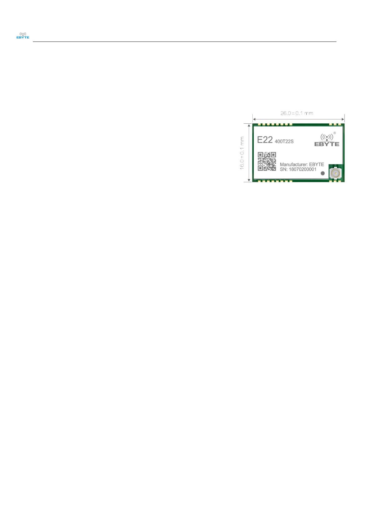
l IPEX and stamp hole optional, good for secondary development and integration.
1.3 Application
l Home security alarm and remote keyless entry
l Smart home and industrial sensors
l Wireless alarm security system
l Building automation solutions
l Wireless industrial-grade remote control
Chengdu Ebyte Electronic Technology Co., Ltd. E22-400M22S User manual
Copyright ©20122018,Chengdu Ebyte Electronic Technology Co.,Ltd.
3
l Health care products
l Advanced Meter Reading Architecture(AMI)
l Automotive industry applications.
2. Specification and parameter
2.1 Limit parameter
Main parameter
Performance
Remark
Min.
Max.
Power supplyV
0
3.7
Voltage over 3.7V will cause permanent
damage to module
Blocking powerdBm
-
10
Chances of burn is slim when modules are
used in short distance
Operating temperature
-40
85
-
2.2 Operating parameter
Main parameter
Performance
Remark
Operating voltageV
3.7 V ensures output power
Communication levelV
For 5V TTL, it may be at risk of burning
down
Operating temperature
Industrial design
Operating frequencyMHz
Support ISM band
Power
consumpti
on
TX currentmA
Instant power consumption
RX currentmA
-
Sleep current μA
Software is shut down
Max Tx powerdBm
-
Receiving sensitivitydBm
Air data rate is 0.3kbps
Air data ratebps
0.6k
-
300k
Controlled via user’s programming
0.018k
-
62.5k
Controlled via user’s programming
Main parameter
Description
Remark
Distance for reference
7000m
Test conditionclear and open area, antenna gain: 5dBi
antenna height: 2.5mair data rate: 0.3kbps
FIFO
256Byte
Maximum length of single transmission
Crystal frequency
32MHz
-
Modulation
LoRa
-
Package
SMD
-
Connector
1.27mm
Stamp hole
Chengdu Ebyte Electronic Technology Co., Ltd. E22-400M22S User manual
Copyright ©20122018,Chengdu Ebyte Electronic Technology Co.,Ltd.
4
Communication interface
SPI
0-10Mbps
Size
20* 14*2.8 mm
-
Antenna
IPEX/stamp hole
50 ohm impedance
3. Size and pin definition
No.
Name
Direction
Function
1
GND
-
Ground
2
GND
-
Ground
3
GND
-
Ground
4
GND
-
Ground
5
GND
-
Ground
6
RXEN
Input
RF switch receiving control pin, connected to external microcontroller IO, valid in high level
Chengdu Ebyte Electronic Technology Co., Ltd. E22-400M22S User manual
Copyright ©20122018,Chengdu Ebyte Electronic Technology Co.,Ltd.
5
7
TXEN
Input
RF switch transmitting control pin, connected to external microcontroller IO or DIO2, valid in high
level
8
DIO2
Input/Output
Configurable universal IO port (see SX1262 manual for details)
9
VCC
Output
Power supply, 1.8V~3.7V (it is recommended to add external ceramic filter capacitor)
10
GND
Ground
11
GND
Ground
12
GND
Ground
13
DIO1
Input/Output
Configurable universal IO port (see SX1262 manual for details)
14
BUSY
Output
For status indication (see SX1262 manual for details)
15
NRST
Input
Chip reset trigger input pin, valid in low level
16
MISO
Output
SPI data output pin
17
MOSI
Input
SPI data input pin
18
SCK
Input
SPI clock input pin
19
NSS
Input
Module chip select pin for starting an SPI communication
20
GND
Ground
21
ANT
Antenna interface, stamp hole (50 ohm characteristic impedance)
22
GND
Ground
4. Basic Operation
4.1 Hardware Design
l It is recommended to use DC stabilized power supply to supply power to the module. The power supply ripple
coefficient is as small as possible, and the module needs to be reliably grounded.
l Please pay attention to the correct connection of the positive and negative poles of the power supply. If the reverse
connection is connected, the module may be permanently damaged.
l Please check the power supply to ensure that between the recommended supply voltage, if exceeding the maximum,
the module will be permanently damaged.
l Please check the stability of the power supply, the voltage can not be significantly frequent.
l When designing the power supply circuit for the module, it is often recommended to reserve more than 30% of the
margin, and the whole machine is beneficial for long-term stable operation.
l The module should be as far away as possible from the power supply, transformers, high-frequency wiring and other
parts with large electromagnetic interference.
l High-frequency digital traces, high-frequency analog traces, and power traces must be avoided under the module. If
it is necessary to pass through the module, assume that the module is soldered to the Top Layer, and the copper is
Chengdu Ebyte Electronic Technology Co., Ltd. E22-400M22S User manual
Copyright ©20122018,Chengdu Ebyte Electronic Technology Co.,Ltd.
6
spread on the Top Layer of the module contact part(All copper-covered and well grounded), and must be close to the
digital part of the module and routed in the Bottom Layer.
l Assuming the module is soldered or placed in the Top Layer, it is also wrong to randomly route the Bottom Layer or
other layers, which will affect the module's spurs and receiving sensitivity to varying degrees.
l Assume that there are traces with large electromagnetic interference around the module (high-frequency digital, high-
frequency analog, power trace), which will greatly affect the performance of the module. It is recommended to stay
away from the module according to the strength of the interference. If necessary, appropriate isolation and shielding
can be done;
l If the communication line uses a 5V level, a 1k-5.1k resistor must be connected in series (not recommended, there is
still a risk of damage).
l Try to stay away from some physical layers and also have a 2.4GHz TTL protocol, for example: USB3.0
l The antenna mounting structure has a great influence on the performance of the module. It is necessary to ensure that
the antenna is exposed, preferably vertically upward. When the module is mounted inside the case, use a good antenna
extension cable to extend the antenna to the outside of the case.
l The antenna must not be installed inside the metal case, which will greatly reduce the transmission distance.
l It is recommended to add a 200R protection resistor to the RXD/TXD of the external MCU.
4.2 Software Programming
l This module is SX1268/SX1262+PA+LNA. Its driving mode is exactly the same as SX1268/SX1262. Users can
operate according to SX1268/SX1262 chip datasheet.
l DIO1 and DIO2 are general-purpose IO ports, which can be configured into multiple functions. DIO2 can be
connected to TXEN and not connected to the MCU's IO port. It can be used to control the RF switch transmission. If
not used, you can hang it. For details, see the SX1262 manual.
l DIO 3 is used to supply 32 MHz TCXO crystal oscillator.
Chengdu Ebyte Electronic Technology Co., Ltd. E22-400M22S User manual
Copyright ©20122018,Chengdu Ebyte Electronic Technology Co.,Ltd.
7
5. Basic application
5.1 Basic circuit
6. FAQ
6.1 Communication range is too short
l The communication distance will be affected when obstacle exists.
l Data lose rate will be affected by temperature, humidity and co-channel interference.
l The ground will absorb and reflect wireless radio wave, so the performance will be poor when testing near ground.
l Sea water has great ability in absorbing wireless radio wave, so performance will be poor when testing near the sea.
l The signal will be affected when the antenna is near metal object or put in a metal case.
l Power register was set incorrectly, air data rate is set as too high (the higher the air data rate, the shorter the distance).
l When the power supply at room temperature is lower than the recommended low voltage, the lower the voltage is,
the lower the transmitting power is.
l Due to antenna quality or poor matching between antenna and module.
Chengdu Ebyte Electronic Technology Co., Ltd. E22-400M22S User manual
Copyright ©20122018,Chengdu Ebyte Electronic Technology Co.,Ltd.
8
6.2 Module is easy to damage
l Please check the power supply and ensure it is within the recommended range. Voltage higher than the peak will lead
to a permanent damage to the module.
l Please check the stability of power supply and ensure the voltage not to fluctuate too much.
l Please make sure anti-static measures are taken when installing and using, high frequency devices have electrostatic
susceptibility.
l Please ensure the humidity is within limited range for some parts are sensitive to humidity.
l Please avoid using modules under too high or too low temperature.
6.3 High bit error rate
l There are co-channel signal interference nearby, keep away from interference sources or modify frequency, channel
to avoid interference.
l The clock waveform on the SPI is not standard. Check whether there is interference on the SPI line. The SPI bus line
should not be too long.
l Unsatisfactory power supply may also cause garbled characters, and ensure the reliability of the power supply.
l If the extension cable or feeder is of poor quality or too long, the bit error rate will be high.
7. Welding operation guidance
7.1 Reflow Soldering Temperature
Profile Feature
Curve feature
Sn-Pb Assembly
Pb-Free
Assembly
Solder Paste
Solder paste
Sn63/Pb37
Sn96.5/Ag3/Cu0.5
Preheat Temperature min Tsmin
Minimum preheating temperature
100
150
Preheat temperature max (Tsmax)
Maximum preheating temperature
150
200
Preheat Time (Tsmin to Tsmax)(ts)
Preheating time
60-120 sec
60-120 sec
Average ramp-up rate(Tsmax to Tp)
Average rising rate
3℃/second max
3℃/second max
Liquidous Temperature (TL)
Liquid phase temperature
183
217
TimetLMaintained AboveTL
Time above liquidus
60-90 sec
30-90 sec
Peak temperatureTp
Peak temperature
220-235
230-250
Aveage ramp-down rateTp to Tsmax
Average descent rate
6℃/second max
6℃/second max
Time 25℃ to peak temperature
Time of 25 ° C to peak temperature
6 minutes max
8 minutes max
Chengdu Ebyte Electronic Technology Co., Ltd. E22-400M22S User manual
Copyright ©20122018,Chengdu Ebyte Electronic Technology Co.,Ltd.
9
7.2 Reflow Soldering Curve
8. Related Model
Model
Chip
Frequency
Hz
Transmit
power dBm
Test
distance km
Air Data
rate
Packaging
Size
mm
E22-900T22S
SX1262
868M 915M
22
7
SMD
16*26
UART
E22-230T22S
SX1262
230M
22
7
SMD
16*26
UART
E22-400T22S
SX1268
433M 470M
22
7
SMD
16*26
UART
E22-400M30S
SX1268
433M 470M
30
12
SMD
24*38.5
SPI
E22-900M30S
SX1262
868M 915M
30
12
SMD
24*38.5
SPI
E22-900M22S
SX1262
868M 915M
22
6.5
SMD
14*20
SPI
E22-400M22S
SX1268
433M 470M
22
6.5
SMD
14*20
SPI
Chengdu Ebyte Electronic Technology Co., Ltd. E22-400M22S User manual
Copyright ©20122018,Chengdu Ebyte Electronic Technology Co.,Ltd.
10
9. Antenna Type
9.1 Antenna recommendation
The antenna plays an important role in the communication process. The inferior antenna often has a great impact on the
communication system. Therefore, we recommend some antennas that support our wireless modules and have excellent
performance and reasonable price.
Product
Type
Frequency
Hz
Interface
Gain
dBi
Size
Feeder
Features
TX433-NP-4310
Soft PCB
antenna
433M
SMA-J
2
43.8*9.5mm
-
Built-in flexible FPC soft
antenna
TX433-JW-5
Rubber
antenna
433M
SMA-J
2
50mm
-
Flexible, Omnidirectional
TX433-JWG-7
Rubber
antenna
433M
SMA-J
2.5
75mm
-
Flexible, Omnidirectional
TX433-JK-20
Rubber
antenna
433M
SMA-J
3
210mm
-
Flexible, Omnidirectional
TX433-JK-11
Rubber
antenna
433M
SMA-J
2.5
110mm
-
Flexible, Omnidirectional
TX433-XP-200
Sucker
antenna
433M
SMA-J
4
19cm
200cm
High Gain
TX433-XP-100
Sucker
antenna
433M
SMA-J
3.5
18.5cm
100cm
High Gain
TX433-XPH-300
Sucker
antenna
433M
SMA-J
6
96.5cm
300cm
High Gain
TX433-JZG-6
Rubber
antenna
433M
SMA-J
2.5
52mm
-
Ultra short straight
Omnidirectional
TX433-JZ-5
Rubber
antenna
433M
SMA-J
2
52mm
-
Ultra short straight
Omnidirectional
TX490-XP-100
Sucker
antenna
490M
SMA-J
50
12cm
100cm
High Gain
TX490-JZ-5
Rubber
antenna
490M
SMA-J
50
50mm
-
Ultra short straight
Omnidirectional
Chengdu Ebyte Electronic Technology Co., Ltd. E22-400M22S User manual
Copyright ©20122018,Chengdu Ebyte Electronic Technology Co.,Ltd.
11
Revision history
Ver si on
Date
Description
Issued by
1.00
2017/10/16
Original version
huaa
1.10
2018/5/23
Content added
huaa
1.20
2018/9/18
Model No. split
huaa
About us
Technical support: [email protected]
Documents and RF Setting download link: www.ebyte.com
Thank you for using Ebyte products! Please contact us with any questions or suggestions: [email protected]
------------------------------------------------------------------------------------------------------------
Fax: 028-64146160 ext. 821
Web: www.ebyte.com
Address: Innovation Center D347, 4# XI-XIN Road,Chengdu, Sichuan, China
  • Page 1 1
  • Page 2 2
  • Page 3 3
  • Page 4 4
  • Page 5 5
  • Page 6 6
  • Page 7 7
  • Page 8 8
  • Page 9 9
  • Page 10 10
  • Page 11 11
  • Page 12 12

ebyte E22-400M22S User manual

Type
User manual

The ebyte E22-400M22S is a compact and powerful 433/470MHz SMD wireless module based on the SX1268 chip. It offers long-range communication with a range of up to 7km in open areas. With its high transmission power of 160mW, it can penetrate obstacles and maintain a stable connection even in challenging environments. The E22-400M22S supports multiple modulation modes, including LoRa, FSK, and GFSK, allowing for flexible data transmission.

Ask a question and I''ll find the answer in the document

Finding information in a document is now easier with AI