YASKAWA Drive Options Installation guide

Category
Power generators
Type
Installation guide

This manual is also suitable for

Yaskawa Electric America, Inc. – www.drives.com
IG.AFD.60, Page 1 of 8
Date: 07/01/04, Rev:04-07
Encoder Feedback Option Card
PG-X2
1. Part Number: PG-X2.
2. Applicability: F7, G7, GPD515/G5, G5HHP.
3. Introduction: The PG-X2 encoder feedback option card (Figure 1) is mounted on the drive’s Control Board and performs
speed feedback using the pulse generator (PG) on the motor to correct speed fluctuation caused by motor slip. Motor rotation
direction is detected by phase A and phase B PG pulse inputs. The terms encoder, PG (pulse generator), and pulse train are
used interchangeably in this guide. The card can be used for flux vector control or V/Hz with PG feedback control.
4. Receiving: All equipment is tested against defect at the factory. Report any damages or shortages evident when the
equipment is received to the commercial carrier who transported the equipment.
5. Cautions:
a. Hazardous voltage can cause severe injury or death. Lock all power sources feeding the drive in the “OFF” position.
b. This option card uses CMOS IC chips. Use proper electrostatic discharge (ESD) protective procedures when
handling the card to prevent I.C. damage or erratic drive operation.
c. If other option cards are to be installed at the Option C (2CN) or Option D (3CN) positions (See Figure 2), their
installation and wiring should be completed before installation of this option.
d. Before installing this option, a technically qualified individual, who is familiar with this type of equipment and the
hazards involved, should read this entire installation guide.
Figure 1. PG-X2 Encoder Feedback Card Figure 2. PG-X2 Option Card installation
Mounting Hole
Connector, Rear
Side of Board to
Control Bd., 4CN
Terminal
Block TA2
Terminal
Block TA1 Variable Resistor,
Adjusts
+12V PG Power
Variable Resistor,
Adjusts
+5V PG Powe
r
Terminal TA3
Connect Shield
Here
2 Mounting Holes
Ground Lead Wire-
Connects to Grounding
Terminal on Control Board
Yaskawa Electric America, Inc. – www.drives.com
IG.AFD.60, Page 2 of 8
Date: 07/01/04, Rev:04-07
Encoder Feedback Option Card
PG-X2
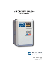
Figure 3. Mounting Spacer
6. Precautions and Preliminary Installation:
a. Remove contents from package. Verify that a mounting spacer
(P/N 5RNT41028-9) is included with the card. See Figure 3.
b. Disconnect all electrical power to the drive.
c. Remove the drive’s front cover.
d. Check that the “CHARGE” indicator lamp inside the drive is off.
e. Use a voltmeter to verify voltage at incoming power terminals
(L1, L2, L3) has been disconnected.
f. Insert the spacer into the mounting hole in the base of the drive,
just above the top edge of the control board. See Figure 2.
g. Note: When re-installing the cover, please take care not to pinch
any of the encoder wires.
h. Important: GPD 515/G5 models 20P2 to 22P2 and 40P2 to 41P5 have two closely spaced mounting holes. Insert
the spacer into the hole closest to the control board’s connector 4CN. If inserted in the wrong hole, the spacer WILL
NOT properly align with the PG-W2’s mounting hole.
7. PG-X2 Installation: See Figure 2.
a. Position the bottom edge of the option card into the mounting bracket on the control board’s terminal block. Align two
mounting holes in the card with pins on the bracket.
b. Then angle the top edge of the card into place, carefully aligning connector 4CN on the back of the card with
connector 4CN on the control board. Gently press the card into place until 4CN and the spacer click into place.
8. Wiring: Refer to Figure 4 and Tables 1 & 2. Make wire connections between the PG-X2 card and encoder as well as any
external monitoring circuits. Observe the following:
a. The need for the marker Z (C) channel depends on the installed custom (CASE) software. Standard software does
not use the marker pulse.
b. Keep the PG-X2 (i.e. control circuit) wiring separate from main circuit input/output wiring. A separate metallic
grounded conduit with ONLY the PG wiring running through it is preferred.
c. To prevent erroneous operation caused by noise interference, use shielded cable for control signal wiring, and limit
the distance to 50m (165 feet) or less.
d. Recommended cable is twisted pair, 22AWG, with overall shield, such as Belden 9504. Refer to “Electrical
Installation” in the drive technical manual for further information on use of shielded cable. The shielded sheath
connection points on the PG-X2 card are terminal TA3.
e. Strip back insulation for a distance of 0.22 in. on wire leads connected to the PG-X2 terminals.
f. Connect the option card ground wire (E) to the drive’s ground terminal TB3 (12 for G5).
9. Adjustment: The+12VDC and +5VDC outputs of the PG-X2 card are factory calibrated. No adjustment should be
necessary.
10. Cover: Reinstall and secure drive’s front cover.
11. Programming: Table 3 lists all drive parameters related to encoder feedback. Ensure that all of these parameters are
programmed to meet the requirements of the application.
12. Start-up: Refer to Section 2 in the drive’s technical manual for testing and start-up information.
13. IG Storage: Place this instruction guide with the drive’s technical manual.
Yaskawa Electric America, Inc. – www.drives.com
IG.AFD.60, Page 3 of 8
Date: 07/01/04, Rev:04-07
Encoder Feedback Option Card
PG-X2
Table 1. Terminal Functions
Terminal
Block Terminal
Number Function
1 +12VDC
Power supply for Pulse Generator (PG).
Important: Use either +12V or +5V, but never both at the same time.
2 0V +12VDC, 200mA max
3 +5VDC +5VDC, 200mA max
4 +
5 - A Pulse
6 +
7 - B Pulse
8 +
9 - Z Pulse*
TA1
10 0V Common Terminal
PG Signal Inputs
RS-422 Level Input
1 +
2 - A Pulse
3 +
4 - B Pulse
5 +
6 - Z Pulse*
TA2
7 IG5 Isolated Common Terminal
Pulse Monitor Output
RS-422 Level Output
TA3 Shield Drain for Encoder Wiring
* Not required for standard software. May be required for custom software.
Table 2. Terminal and Wire Specifications
Terminal Symbol Terminal
Screw Clamping Torque
Lb-in (N-m) Wire Range
AWG (mm 2)
TA1, TA2 M2 1.8 to 2.2
(0.22 to 0.25)
26 to 16
(Stranded: 0.14 to 1)
(Solid: 0.14 to 1.5)
Yaskawa Electric America, Inc. – www.drives.com
IG.AFD.60, Page 4 of 8
Date: 07/01/04, Rev:04-07
Encoder Feedback Option Card
PG-X2
Figure 4. PG-X2 Interconnection Diagram
Notes:
(1) Power Supply for PG (from PG-X2)
TA1 1-2: +12VDC, 200mA max.
Ta1 3-2: +5VDC, 200mA max
Do Not Use Both Supplies at the
Same Time.
(2) H20 Dynapar Encoder Connections Shown
Yaskawa Electric America, Inc. – www.drives.com
IG.AFD.60, Page 5 of 8
Date: 07/01/04, Rev:04-07
Encoder Feedback Option Card
PG-X2
Figure 5. Using Separate PG Power Supply
14. Application: If the encoder’s power requirement is greater than 200mA, provide a separate power supply source as
shown in Figure 5. If the momentary power loss ride thru function of the drive is to be used, include a backup capacitor in the
PG power wiring or take other necessary precautions.
PG ENCODER
1
2
3
IP12
(2)
4
5
6
7
8
9
10
12V
0V
P
P
PG-X2 Card TA1
TA3
0V 12V
PG Power Suppl
y
AC
+
*
*Backup capacitor, for momentary
power loss recovery function
IG
IP5
A (+)
A (–)
B (+)
B (–)
Z (+)
Z (–)
IG
P
15. Maximum Input Frequency: The maximum input frequency of the PG-W2 card is 300kHz. To find the output frequency
of the encoder (PG) in Hertz, use the following formula. Please make sure a 20% safety margin is built-in.
fPG (Hz) = Maximum Motor Speed (RPM) x Encoder PPR (Pulses/Rev)
60
Yaskawa Electric America, Inc. – www.drives.com
IG.AFD.60, Page 6 of 8
Date: 07/01/04, Rev:04-07
Encoder Feedback Option Card
PG-X2
Figure 6. Encoder (PG) Signals – Forward Direction
16. Signal type / level requirements: The PG-X2 card requires a “quadrature line driver with compliments” signal type from
the encoder (pulse generator). As shown in Figure 6, line driver signals include both a primary signal (Signal A+) and it’s
compliment (Signal A-). The compliment is the inverse of the primary signal. This scheme is used to improve the noise
immunity of the system. The encoder output signal voltage should be between +5VDC and +12VDC. An “open collector”
signal type WILL NOT work with the PG-X2 card.
A quadrature signal is one that lags the primary signal by 90 electrical degrees (1/2 of a pulse). The purpose of this is so that
the drive can detect the direction of the encoder rotation. As shown in Figure 6, for “forward” rotation of the encoder, signal A+
will lead signal B+ by 90o.
If any one of the four signals is missing, the drive cannot accurately measure the encoder rotation speed or direction.
17. Viewing Signals With An Oscilloscope: The PG-X2 option card has test points that can be used to connect an
oscilloscope. Test points PA, PB, and PZ are after the compliment is subtracted out and the signals are buffered through the
opto-isolators. See Figure 4. The voltage level on all test points varies between 0 and +5VDC (TTL).
Caution: Always use an un-grounded oscilloscope so no noise is introduced into the common.
Table 3. PG-X2 Test Points
Test Point Description
GND Although labeled GND, it is NOT earth ground. This test point should only be used in conjunction
with test points PA, PB, and PZ.
PA Channel A (Terminals 4 & 5)
PB Channel B (Terminals 6 & 7)
PZ Channel Z (Terminals 8 & 8)
Note: All signals shown are in relation to power supply common, Terminal 2 of the PG-X2.
Yaskawa Electric America, Inc. – www.drives.com
IG.AFD.60, Page 7 of 8
Date: 07/01/04, Rev:04-07
Encoder Feedback Option Card
PG-X2
Table 3. GPD 515/G5, F7, and G7 Encoder Feedback Parameter List
Control
Method (2)
Digital Operator
Function Group
Digital Operator
Display
Parameter Number
Parameter Name
Setting Range
Factory Setting
Change During
Operation (1)
Data Selection
V/f w/ PG
Feedback
Flux Vector
PG Pulse/Rev F1-01 PG Constant 0 to
60000 1024 X O O
PG Fdbk Loss
Sel F1-02 Operation at
Open PG
Circuit 0 to 3 1 X O O
PG Overspeed
Sel F1-03 Operation
Selection at
Overspeed 0 to 3 1 X O O
PG Deviation
Sel F1-04 Operation
Selection at
Deviation 0 to 3 3 X
0: Ramp to Stop
1: Coast to Stop
2: Fast-Stop
3: Alarm Only
O O
PG Rotation
Sel F1-05 PG Rotation 0,1 0 X 0: Fwd = CCW
1: Fwd = CW O O
PG Ramp PI/I
Sel F1-07 Integral
Control during
Accel/Decel 0,1 0 X 0: Disabled
1: Enable O X
PG Overspeed
Level F1-08 Overspeed
Detection
Level
0 to
120% 115% X O O
PG Overspeed
Time F1-09 Overspeed
Detection
Delay Time 0 to 2.0s 1.0s X O O
PG Deviation
Level F1-10
Speed
Deviation
Detection
Level
0 to 50% 10% X O O
PG Deviation
Time F1-11
Speed
Deviation
Detection
Delay Time
0 to 10s 0.5s X O O
PG# Gear
Teeth 1 F1-12 Number of
Gear Teeth 1 0 to 1000 0 X O X
PG# Gear
Teeth 2 F1-13 Number of
Gear Teeth 2 0 to 1000 0 X O X
PGO Detect
Time F1-14 PGO Detection
Time 0 to 10s 2s X O O
PG
Option
Setup
Speed
Detection
Filter Selection F1-15 Speed
Detection Filter
Selection 0, 1 1 X 0: No Average
1: 2 Scan Moving
Average O O
Yaskawa Electric America, Inc. – www.drives.com
IG.AFD.60, Page 8 of 8
Date: 07/01/04, Rev:04-07
Encoder Feedback Option Card
PG-X2
Table 3. GPD 515/G5, F7, and G7 Encoder Feedback Parameter List
Control
Method (2)
Digital Operator
Function Group
Digital Operator
Display
Parameter Number
Parameter Name
Setting Range
Factory Setting
Change During
Operation (1)
Data Selection
V/f w/ PG
Feedback
Flux Vector
ASR P Gain 1 C5-01 ASR
Proportional
Gain 1
0 to
300.00 0.00 O O O
ASR I Time 1 C5-02 ASR Integral
Time 1 0 to
10.000s 0.00s O O O
ASR P Time 2 C5-03 ASR
Proportional
Gain 2
0 to
300.00 0.00 O O O
ASR I Time 2 C5-04 ASR Integral
Time 2 0 to
10.000s 0.00s O O O
ASR Limit C5-05 ASR Limit 0.0 to
20% 0.0% X O X
ASR Delay
Time C5-06 ASR Primary
Delay Time 0.000 to
0.500s 0.000s X X O
ASR Gain SW
Freq C5-07 ASR Switching
Frequency 0.0 to
400.00Hz 0.0Hz X X O
ASR
Tuning
ASR Integral
Limit C5-08 ASR Integral
Limit 0 to
400% 400% X X O
(1) O = Yes, X = No.
(2) O = Available, X = Hidden. The PG-X2 is not applicable for A1-02 = 0 (V/f Control) or 2 (Open Loop Vector).
  • Page 1 1
  • Page 2 2
  • Page 3 3
  • Page 4 4
  • Page 5 5
  • Page 6 6
  • Page 7 7
  • Page 8 8

YASKAWA Drive Options Installation guide

Category
Power generators
Type
Installation guide
This manual is also suitable for

Ask a question and I''ll find the answer in the document

Finding information in a document is now easier with AI