Page is loading ...

Service Manual
Trucks
Group 330–500
Starting and Charging
VN, VHD
PV776-TSP146025


Foreword
The descriptions and service procedures contained in this manual are based on de-
signs and methods studies carried out up to March 2001.
The products are under continuous development. Vehicles and components produced
after the above date may therefore have different specifications and repair methods.
When this is believed to have a significant bearing on this manual, supplementary ser-
vice bulletins will be issued to cover the changes.
The new edition of this manual will update the changes.
In service procedures where the title incorporates an operation number, this is a refer-
ence to an S.R.T. (Standard Repair Time).
Service procedures which do not include an operation number in the title are for gen-
eral information and no reference is made to an S.R.T.
The following levels of observations, cautions and warnings are used in this Service
Documentation:
Note: Indicates a procedure, practice, or condition that must be followed in order to
have the vehicle or component function in the manner intended.
Caution: Indicates an unsafe practice where damage to the product could occur.
Warning: Indicates an unsafe practice where personal injury or severe damage to the
product could occur.
Danger: Indicates an unsafe practice where serious personal injury or death could oc-
cur.
Volvo Trucks North America, Inc.
Greensboro, NC USA
Order number: PV776-TSP146025
© 2001 Volvo Trucks North America, Inc., Greensboro, NC USA
All rights reserved. No part of this publication may be reproduced, stored in
retrieval system, or transmitted in any forms by any means, electronic, me-
chanical, photocopying, recording or otherwise, without the prior written
permission of Volvo Trucks North America, Inc..


Contents
General .................................................................................................... 3
Starting and Charging ........................................................................... 3
Tools ........................................................................................................ 5
Special Tools ......................................................................................... 5
Design and Function ............................................................................. 9
Starting and Charging System Indicator Lights .................................... 9
Battery ................................................................................................... 9
Cold Cranking Amps ....................................................................... 10
Reserve Capacity ............................................................................ 10
Open Circuit Voltage ....................................................................... 10
Battery Locations .............................................................................. 10
Battery Cables ................................................................................... 11
Battery Disconnect Switch ................................................................ 11
Starting System ................................................................................... 12
Starting Circuit ................................................................................... 12
Starter ................................................................................................ 13
Preheat System ................................................................................... 13
Preheat Circuit ................................................................................... 13
Preheater Assembly .......................................................................... 14
Charging System ................................................................................. 15
Charging Circuit ................................................................................. 15
Alternator ........................................................................................... 16
Troubleshooting ................................................................................... 17
Battery Troubleshooting ....................................................................... 17
Battery State of Charge .................................................................... 18
Battery Surface Charge Removal ..................................................... 19
Load Testing Batteries ....................................................................... 20
Electronic Battery Testing .................................................................. 21
Starting System Troubleshooting ......................................................... 22
Troubleshooting Simplified Schematic, Starting System ................... 23
Troubleshooting Ignition Switch with VCADS Pro Tool ..................... 24
Troubleshooting Battery/Starter Cables With Digital Multimeter ....... 25
Troubleshooting Ignition Switch/Starter Relay Circuit With Digital
Multimeter .......................................................................................... 26
Troubleshooting Starter with Digital Multimeter ................................ 27
Preheat System Troubleshooting ........................................................ 28
Troubleshooting Preheater with VCADS Pro Tool ............................. 29
Troubleshooting Preheater with Fault Codes .................................... 29
Troubleshooting Simplified Schematic, D7 Preheater ....................... 30
Troubleshooting Simplified Schematic, D12 Preheater ..................... 31
Troubleshooting Preheater with Digital Multimeter ............................ 32
Charging System Troubleshooting ...................................................... 33
Troubleshooting Simplified Schematics, Charging System ............... 34
Troubleshooting Charging System with Digital Multimeter ................ 35
Troubleshooting Charging Indicator (Telltale) Lamp .......................... 37
Troubleshooting — Alternator Output Test with BVA-34 Tester ........ 38
Troubleshooting Starting and Charging System with The Accu-
racy Plus Tester ................................................................................. 39
Service Procedures ............................................................................. 41
Battery Cables, Removal and Installation ........................................... 41
All Cables .......................................................................................... 41 1

Ground Cables .................................................................................. 42
Battery Jump Starting .......................................................................... 43
Battery, Replacement (One or Two) .................................................... 44
Battery Cables to Starter, Replacement ............................................. 45
Battery Inter-connection Cables, Replacement ................................... 47
Starter Motor, Replacement ................................................................ 49
Volvo D12B or D12C Engine ............................................................. 49
Starter Motor, Replacement ................................................................ 51
Volvo D7C Engine ............................................................................. 51
Starter Motor, Replacement ................................................................ 53
Cummins or Detroit Diesel Engine .................................................... 53
Preheater Fuse, Replacement ............................................................ 55
Preheater Relay, Replacement ............................................................ 56
Volvo D12B or D12C Engine ............................................................. 56
Preheater Relay, Replacement ............................................................ 58
D7C Engine ....................................................................................... 58
Preheater Element, Replacement ....................................................... 59
D12B or D12C Engine ...................................................................... 59
Preheater Element, Replacement ....................................................... 60
D7C Engine ....................................................................................... 60
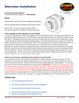
Alternator, Replacement (Adjustable Mount) ...................................... 62
Alternator, Replacement (Fixed Mount) .............................................. 63
Feedback
Operation Numbers
2

Group 33 Starting and Charging VN, VHD General
General
Starting and Charging
The starting and charging system on the VN/VHD series vehicles is comprised of batteries, the starter, alternator and
all the connecting wiring, cables and switches. Vehicles equipped with Volvo engines may also have preheaters in-
stalled in the intake manifold to assist starting. For maximum efficiency, all parts of the system must function properly.
Note: The information in this manual pertains specifically to the Volvo VN/VHD series vehicles.
For more general information on the starting and charging system, including test, refer to:
Vendor
Information Diagnostic Procedures For Heavy Duty Electrical Systems
Delco Remy DRA/DP1029
W3004734
Starting and Charging Circuit, Simplified Schematic.
This simplified schematic should only be used to clarify the design features of the VN/VHD starting and charging cir-
cuit. For detailed vehicle-specific schematics, refer to:
Service
Manual Electrical Schematics VN, VHD
IMPACT Function Group: 370
Information Type: Schematics
3

4

Group 33 Starting and Charging VN, VHD Tools
Tools
Special Tools
The tools referenced in this manual are listed below. They can be obtained by contacting your local Volvo Trucks parts
dealer, Kent-Moore at 1–800–328–6657, or you may call a local listed tool vendor.
Note: For VCADS Pro tooling refer to:
Service
Manual VCADS Pro User’s Manual
Group Number 030–600
Battery tester kit. Includes: Tester J-44700 and Printer
238598, available from Kent-Moore (telephone: 800–
328–6657).
J-44701
W0001836
Fluke 87 digital multimeter, available from Volvo or Kent-
Moore (telephone: 800–328–6657).
J-39200
W2001014
5

Group 33 Starting and Charging VN, VHD Tools
Relay puller tool, available from Kent-Moore (telephone:
800–328–6657).
J-43244
W0001917
VCADS Pro
For VCADS Pro tooling refer to:
Service
Manual VCADS Pro User’s Manual
Group Number 030–600
W0001632
Fan Belt Tensioner Tool, available from Volvo or Kent-
Moore (telephone: 800–328–6657).
J-44392
W0001817
(BT-33–73F) Belt Tension Gauge, available from Kent-
Moore (telephone: 800–328–6657).
J-23600–B
W0001844
6

Group 33 Starting and Charging VN, VHD Tools
BVA-34 System Analyzer
The BVA-34 System Analyzer is a digital, carbon pile,
battery load tester and starting/charging system ana-
lyzer. It is portable and designed for use in the heavy
truck market. Optional tester stand, part number ES-2, is
also available . For more information contact Auto-
Meter®(telephone: 435–283–4142) or visit their web site
at www.autometer.com.
W3004737
7

8

Group 33 Starting and Charging VN, VHD Design and Function
Design and Function
Starting and Charging System Indicator Lights
When the ignition key is turned “ON,”the Charging Indi-
cator (telltale) lamp (1) will momentarily illuminate for a
bulb test. The lamp will remain on until the engine is
started. With the engine running and the alternator prop-
erly charging, the Charging telltale light should go off.
The instrument cluster left module is equipped with a
graphics display (2) that includes a voltmeter function.
With the voltmeter function active, the display will show a
battery icon and display the battery/charging voltage.
W3004552
If the battery/charging voltage exceeds 17 volts, the yel-
low “INFO”lamp (3) will illuminate and the graphic
display will show the voltage reading with the text mes-
sage “TOO HIGH.”T3008832
TOO HIGH
17.9 V
Battery
The battery is an electrochemical device for converting
chemical energy into electrical energy. The battery, or
battery pack, performs four basic functions:
1 It supplies energy for starting the engine.
2 It supplies energy to operate all the vehicles electri-
cal systems and accessories.
3 It acts as a voltage stabilizer for the electrical sys-
tem.
4 It supplies additional energy to operate the electrical
system during peak demands, for instance, when
the alternator is already at maximum output.
The battery case (1) is made of a strong, lightweight ma-
terial, commonly polypropylene, to withstand shock and
vibration. The cover is vented to allow chemical gases to
escape. Each battery cell (2) is constructed of positive
and negative plates (3) that are insulated from each
other by a porous separator (4). Plate straps (5) connect
the positive and negative plates and provide a means of
interconnecting the cells. The cell is immersed in an
electrolyte solution of sulfuric acid and water. The electri-
cal energy is produced in the battery by the chemical
reaction of the active materials that comprise the positive
and negative plates and the electrolyte. Each cell will
produce approximately 2.1 volts. The six cells that com-
prise the battery are connected in series to deliver
approximately 12.6 volts at the battery post (6).
W3004553
9

Group 33 Starting and Charging VN, VHD Design and Function
Cold Cranking Amps
The “Cold Cranking Amps”rating is the amount of am-
perage load that can be maintained at –18 C(0F)
without the post voltage falling below 7.2 volts. This
rating is useful in determining the battery’s ability to
start an engine in cold weather conditions. The cold
cranking amp rating is determined by the amount of
plate surface area in each cell.
Reserve Capacity
The “Reserve Capacity”is the number of minutes that
a battery can sustain a 25 Amp load at 27 C (80 F)
until the post voltage drops to 10.5 volts. This rating is
useful in determining the battery’s ability to supply
operating power in the event of a vehicle charging sys-
tem failure. The reserve capacity is determined by the
amount of active plate material in each cell.
Open Circuit Voltage
The “Open Circuit Voltage”is the voltage at the battery
post with no loads applied.
Battery Locations
Battery box locations vary per application. The stan-
dard mounting location (1) is on the left frame rail
under the cab steps. This is the mounting location for
all VN and some VHD vehicles. Depending on the
equipment ordered, there are three optional battery
box mounting locations for the VHD vehicle. See illus-
tration for locations: (2), (3) and (4).
W3004555
10

Group 33 Starting and Charging VN, VHD Design and Function
Battery Cables
All copper, 3/0 battery cables (1) are used on VN/VHD
vehicles. Single cables are used if the batteries are
mounted in the standard location. If the batteries are
mounted in optional locations, dual cables are used to
prevent excessive voltage drop due to cable length. Bat-
tery inter-connection cables (2) are 2/0 size. Some
applications may use interconnection bars instead of ca-
bles. All battery cables are sealed with polyvinyl chloride
(PVC) insulation to resist abrasion and the elements.
The battery cable terminals are secured to the batteries
with either stainless steel terminal nuts (3) or brass
jumper studs (4). Some applications may be equipped
with insulated terminal nuts that are made of plastic with
a brass insert. Protective covers (6) are installed on all
uninsulated battery cable terminal nuts/studs. Mounting
brackets (5) support and secure the battery cables at ap-
proximately 300 mm (12 in.) to 600 mm (24 in.) intervals
to avoid damage from abrasion, vibration, heat and
strain.
Ideally, battery sets should be connected to the bat-
tery/starter cables in a diagonal pattern (1) rather than
both cables being connected to one battery at the end of
the set (2). The diagonal connection will help assure that
all batteries in the set are cycled at the same rate, ex-
tending service life.
W3004556
W3004557
Battery Disconnect Switch
As an option, some vehicles may have a master battery
disconnect switch (main switch). The switch will be
mounted on or near the battery box in all applications.
The battery disconnect switch should not be used as a
substitute for removing battery cables to prevent damage
to the vehicle when welding.
W3004404
11

Group 33 Starting and Charging VN, VHD Design and Function
Starting System
Starting Circuit
When the ignition switch is turned to the “START”posi-
tion, power to energize the starter relay coil is supplied
on wire number 284. The starter relay coil is grounded
through the overcrank protection switch (OCP) or a
shorting jumper.
The OCP switch is located inside the starter. This switch
is optional. Where the OCP switch is not used, a short-
ing jumper is used to complete the starter relay coil
ground circuit.
W3004339
overcrank protection (OCP) input switch.
When the starter relay is energized, a connection is
made from the starter solenoid BATT terminal (wire
285A) to the starter solenoid SW terminal (wire 285).
When the solenoid pulls in, a connection is made inter-
nally in the solenoid, which connects the battery terminal
to the motor terminal, then the starter begins to crank
the engine.
For more details see schematic in “Starting and Charg-
ing”page 3.
W3003757
Starter Relay.
12

Group 33 Starting and Charging VN, VHD Design and Function
Starter
Volvo VN/VHD vehicles are equipped with Delco Remy-
42MT starters for most applications. If the vehicle is
equipped with a Volvo D7 engine, it will be equipped with
a Delco-Remy 37MT starter. These starters, sometimes
referred to as starting motors, have a shift lever and so-
lenoid housing that is totally enclosed to protect them
from the elements. The nose housing can be rotated to
“clock”the solenoid to accommodate various engine
mounting locations. A positive engagement shift mecha-
nism moves the pinion into mesh with the engine
flywheel ring gear prior to cranking to minimize gear
tooth damage. An optional overcrank protection (OCP)
switch protects the starter in adverse starting conditions,
such as cold weather starting or operator misuse. The
OCP switch is a temperature sensitive circuit breaker
that prevents overcrank heat damage by opening the
starter relay ground, then automatically resetting when
the starter has cooled sufficiently.
W3004558
1Solenoid
2Shift Lever Housing
3Nose Housing
4Pinion
5Overcrank Protection Input Switch
Preheat System
Preheat Circuit
Vehicles equipped with Volvo engines may be equipped
with intake air preheaters to assist in cold weather start-
ing.
Preheating is standard on the D7 engine with one pre-
heat relay/element, and optional on the D12 engine with
two preheat relays/elements.
In normal operation, the ignition switch is turned to the
“preheat”position then released back to the “On”
position. The Vehicle Electronic Control Unit (VECU) rec-
ognizes the preheat request and sends the request to the
Engine Electronic Control Unit (EECU), via the J-1939
Control Data Link. The EECU will supply a ground to the
preheat relay(s), and the preheater will begin to operate.
Based on engine temperature, the EECU will time the in-
terval for preheater operation. The operator may also
hold the ignition switch in the “preheat”position if addi-
tional preheat is desired after the timed preheat period.
The preheat relay(s) coil is supplied ignition power via a
fuse in the Truck Electrical Center (TEC) panel. The re-
lay(s) is energized when a ground is supplied by the
EECU. When the relay(s) is energized, an internal con-
nection is made that connects the preheater element
power supply from the alternator cable to the fuse that
connects to the preheat element(s). The preheat ele-
ment(s) are case grounded.
A“sense”circuit(s) provides information to the EECU to
confirm that the preheat circuit is intact. If the EECU de-
termines that the circuit is not intact, a fault code(s) will
be generated.
For simplified schematic see: “Starting and Charging”
page 3.
13

Group 33 Starting and Charging VN, VHD Design and Function
Preheater Assembly
WARNING
Use caution when working around the preheat
elements. When active, the elements will heat to ap-
proximately 705 C (1300 F). Allow sufficient time for
the elements to cool to avoid severe burns.
The preheater assembly on a D7 engine is standard with
one relay element and fuse. The preheater assembly on
a D12 engine is optional with two relays, elements and
fuses.
W3004559
1Relay
2Element
3Fuse Assembly
14

Group 33 Starting and Charging VN, VHD Design and Function
Charging System
Charging Circuit
With the engine running, DC voltage is generated at the
alternator output (B+) terminal and supplied to the vehi-
cles electrical system through wire no. 8. The alternator
is grounded by a wire from the ground terminal (B-) on
the alternator case to the engine ground terminal. A
fusible link in the ground circuit is designed to protect the
vehicle electrical system if a short in the alternator, alter-
nator cable or battery cable occurs.
A wire from the alternator indicator light terminal to the
instrument cluster sends a signal to indicate that the
alternator is not charging. Vehicles with body builder ap-
plications may also have a wire from the alternator relay
terminal to provide engine speed information for PTO op-
eration. Also see Starting and Charging Simplified
Schematic in “Starting and Charging”page 3.
W3004731
1Output Terminal (B+)
2Ground Terminal (B-)
3Relay Terminal
4Indicator Light Terminal
5Ground Terminal (B-) 34SI only
15

Group 33 Starting and Charging VN, VHD Design and Function
Alternator
The alternator converts the mechanical energy supplied
by the engine via drive belts into electrical energy that is
used to recharge the batteries and operate the electrical
devices on the vehicle. The alternator produces alternat-
ing current (AC), which is converted to direct current
(DC) by the diodes in the rectifier bridge. The rectifier
bridge also has design features to “clamp”voltage spikes
that may damage vehicle electronics. An internal voltage
regulator limits the charging voltage from 13.8 to 14.2
volts. Volvo VN/VHD vehicles currently are equipped with
one of three different Delco Remy alternators:
•33SI —The 33SI alternator is a brushless design
for longer operating life. It is the standard alternator
used in most applications. It is available with 110
and 135 amp output ratings.
•22SI —The 22SI alternator is a smaller, standard
brush type alternator. It is available with 100, 130
and 145 amp output ratings.
•34SI —The 34SI alternator is internally identical to
the 33SI. The major difference is that the housing
has a fourth mounting lug to withstand higher vibra-
tion applications. The 34SI is currently only used in
VN vehicles equipped with Detroit Diesel engines.
W3004561
16
/