Page is loading ...

2
USER MANUAL
DT-ENG-243-D4-V1 / 201612
DT243-D4
2 WIRE SYSTEM
4.3" COLOR TFT MONITOR
• Please read this manual carefully before using the product you purchase,and keep it well for future use.
• Please note that images and sketch maps in this manual may be different from the actual product.

-2-
CONTENTS
1. Part And Functions .......................................................................................... 1
2. Mounting ........................................................................................................... 2
3. Main Menu ....................................................................................................... 2
4. Basic Door Release Operation ........................................................................ 2
5. Monitoring Door Station / Camera ................................................................ 3
6. Intercom Function............................................................................................ 4
7. Entrance Playback ........................................................................................... 5
8. No Disturb Function ........................................................................................ 5
9. Divert Call ......................................................................................................... 6
10. Opening Staircase Light ................................................................................ 6
11. Setup Function ................................................................................................ 7
12. Monitor Parameter Setting ........................................................................... 7
13. Basic Connection ........................................................................................... 11
14. Screen and Volume Adjustment ................................................................... 11
15. Specications ................................................................................................. 12

-1-
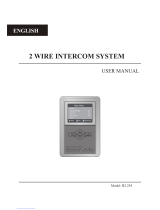
1. Parts And Functions
2
Connection Port
Mounting Hook
Handset
Mounting Hook
Back view
Handset Line
Handset
Handset Line
Speaker
No Disturb button
Call button/Unlock 2nd button
Front view
LCD Screen
Return button
UNLOCK button
Mon/Talk button
Up button
MENU button
Down button
Microphone
1 2
RINGSW- SW+GNDPSAU
3
ON
L1L2
DIP
4 5 6
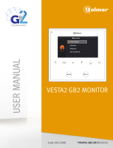
SW+,SW-: Door bell call button connection port.
RING,GND: Extra buzzer connection port.
PSAU: Reserved.
L1,L2: Bus terminal.
DIP switches: Total 6 bits can be congured.
Bit1~Bit5: Used to User Code setting.
Bit6: Set to ON if the monitor is at the end of the line or works with DBC4A1.
Otherwise, set to OFF.
Terminal Description
1 2
RING SW- SW+GNDPSAU
3
ON
L1L2
DIP
4 5 6
1 2
RING SW- SW+GNDPSAU
3
ON
L1L2
DIP
4 5 6

-2-
2. Mounting
145~160 cm
4. Basic Door Release Operation
1. Press CALL button on outdoor station, the
Monitor rings, meanwhile, the screen displays
the visitors' image.
2. Pick up handset (or press Mon/Talk button
on panel), you can communicate hands free
with the visitor for 90 seconds. After nishing
communication, hand up the handset (or press
1. Use the screws to x the Mounting Bracket on the mounting box.(tting accesories
includes a Bracket (Two pieces of 4X25 screws are needed for fastening the
Mounting Bracket), Special 2 wire connectors to connect with Monitor)
2. Wire the system correctly(see the later connection chapter) then hang the Monitor on
the Mounting Bracket rmly.
00:23
DS-1
3. Main Menu
Press Menu button, in standby mode, the main
menu page will be shown as follows:
Monitor By Select
Main Menu
Playback
Don’t Disturb
Intercom Call

-3-
5. Monitoring Door Station / Camera
Mon/Talk button again/or press Return button) to end the communication.
If nobody answers the phone, the screen will be turned off automatically after 40
seconds.
3. During talking state, Press Unlock button to release the rst door. If the system
connect 2 locks, press Call button/Unlock 2nd button to open the second door.
You can monitor the entrance at any time via the monitor.
1. Press Menu button on the panel in standby mode.
2. Select Monitor by Select item on main menu page, and then press Menu button to
enter Select a Camera page.
*Note: Press Mon/Talk button on panel in standby mode to monitor the master door
station in shortcut.
Monitoring door stations/cameras:
DS1~4 and CAM1~4 can be selected to monitor individually if the system installs multi
door stations/cameras.See the following steps:
2 2
Monitor By Select
Main Menu
Playback
Don’t Disturb
Intercom Call
22
DS-1
Select a Camara
DS-3
DS-4
DS-2
00:23
DS-1
* Use / button to move upward / downward to select the item you want.
* During monitoring, images can be viewed, but audio cannot be heard.
* If there is a visitor at the entrance, press Mon/Talk button on panel to begin communication with door
station.

-4-
Inner Call: If multi Monitors are installed in the same apartment, select Inner Call,
all the other Monitors will ring at the same time, whichever Monitor answers the call,
conversation is started, and the other monitors will stop ringing at the same time.(note:the
DIP switches setting of all monitors must be same. )
Call Guard Unit: A Monitor can be assigned as Guard Unit Monitor; when the Guard
Unit Monitor answers the call, conversation with the guard person is started.
6. Intercom Function
When the monitor is in standby mode, press Menu button to enter main menu page.
Use / button to move upward / downward to select Intercom Call item, press
Menu button to enter the select intercom page, you have 3 items to select.
*Note: Press Call button/Unlock 2nd button on panel in standby mode to enter the select
intercom page in shortcut.
Pick up handset, or use /
button to selete Intercom
Call item, then press
Menu button to conrm.
Use / button to selete
Namelist Call item,then
press Menu button to
conrm.
Use / button to selete
the item you want, then press
Menu button to call.
Calling.
Namelist Call
Select Intercom
Inner Call
Call Guard Unit
[01]
Namelist Call
[03]
[04]
[02]
[01]
Namelist Call: User in one apartment can call other apartments in the system. the
namelist will be created automatically by the system. Use / button to selete a name
on the screen then press Menu button to call.(Note:1. Press "MENU" button again to
redial. 2.The DIP switches code of the monitors are not the same.)
Monitor By Select
Main Menu
Playback
Don’t Disturb
Intercom Call

-5-
8. No Disturb Function
If you don't want to be disturbed,for example,at night. Activating the mute function is
necessary for you.
When the monitor is in standby mode, press Menu button to enter main menu page.
Use / button to move upward / downward to select Don't Disturb item, press
Menu button to enter the no disturb page, you have 4 items to select.
Follow the steps:
Monitor By Select
Main Menu
Playback
Don’t Disturb
Intercom Call
Normal
No Disturb
8 H
Always
1 H
Use / button to selete Don't
Disturb item, then press
Menu button to conrm.
Use / button to selete the item
you want, then press Menu
button to conrm.
7. Entrance Playback
When the monitor is in standby mode, press Menu button to enter main menu page.
Use / button to move upward / downward to select Playback item, press Menu
button to conrm, the screen will display the playback page.
*Note: The playback function requires SC6V to support.
*Note: Press No Disturb button on panel in standby mode to enter the no disturb page in
shortcut.

-6-
9. Divert Call
When the monitor is in standby mode, press Menu button to enter main menu page.
Use / button to move upward / downward to select Divert Call item, press Menu
Button to enter the call divert options page, you have 4 items to select. Follow the steps:
Monitor By Select
Main Menu
Playback
Don’t Disturb
Intercom Call
1. No Divert----calls from outdoor station will not be diverted.
2. If No Answer----Calls form outdoor station without respond in 30 seconds will be
transfer to the number you set.
Even though the monitor will shut off when transfer via GSM/TPS, you still available to
operate it (such as monitor, talk, and unlock).
3. Simutaneously----Calls from outdoor station will be diverted to your telephone
immediately.At this mode,the monitor won't shut off when GSM/TPS divert sucessfully,
but if the monitor answers the call at this time, GSM/TPS will quit absolutely.
4. Setup Tel Numbers.----Select this item to edit the divert numbers you want.
Divert Call
Main Menu
Setup
About
Light
No Divert
Call Divert Options
Simultaneously
Setup Tel Numbers.
If No Answer
Use / button to selete
Divert Call item, then press
Menu button to conrm.
Use / button to to scroll
pages.
Use / button to selete the
item you want, then press
Menu button to conrm.
10. Opening Staircase Light
When the monitor is in standby mode, press Menu button to enter main menu page.
Use / button to move upward / downward to select Light item, press Menu
button to enter the light option page, you have 3 items to select.
Divert Call
Main Menu
Setup
About
Light
Turn On
Light Option
Turn Off
Turn On 5min.
Use / button to selete
Light item, then press
Menu button to conrm.
Use / button to selete the
item you want, then press
Menu button to conrm.
Monitor By Select
Main Menu
Playback
Don’t Disturb
Intercom Call
Use / button to to scroll
pages.

-7-
Divert Call
Main Menu
Setup
About
Light
Use / button to selete
About item, then press
Menu button to conrm.
12. Monitor Parameter Setting
12.1 How to enter the installation setting page
Press Unlock button
and hold for 3s.
H/W : a1.1
About
Addr : 00.00
Video STD: AUTO
Restore
S/W : 00.01.00
Use / button to
increase/decrease the value
you want, and press
Menu button to conrm.
[ 0000 ]
Installer Setup
1.Turn On: Select it to open the staircase light, the staircase light will be turned off
automatically after 60 seconds.
2.Turn On 5min:Select it to open the staircase light, the staircase light will be turned off
automatically after 5min.
3.Turn Off:Select it to close the staircase light.
*Note: the staircase light function will be activated only when the system connect light via DT-
RLC module, otherwise, this function is unvalid in normal. For more information, please refer to
DT-RLC user instruction in detail.
1.Ring Tune: Select it to set the tune of Door Station, Intercom and Door Bell.
2.Ring Volume: Select it to set the volume of monitor.
3.Monitor Time: Select it to set monitor time.
4.Language Select: Select it to set the language.
11. Setup Function
When the monitor is in standby mode, press Menu button to enter main menu page.
Use / button to move upward / downward to select Setup item, press Menu
button to enter the user setup page, you have 4 items to select.
Divert Call
Main Menu
Setup
About
Light
Use / button to selete
Setup item, then press
Menu button to conrm.
Ring Tune
User Setup
Monitor Time
Language Select
Ring Volume
Use / button to selete the
item you want, then press
Menu button to conrm.
Monitor By Select
Main Menu
Playback
Don’t Disturb
Intercom Call
Use / button to to scroll
pages.

-8-
Restore?
Press Menu button on About
page.
Press Menu button to confirm.
12.2 Restore to Default
The restore to default function allows the user to recover the settings to factory setting.
Follow the steps:
H/W : a1.1
About
Addr : 00.00
Video STD: AUTO
Restore
S/W : 00.01.00
A Monitor can be assigned as Guard Unit Monitor; when the Guard Unit Monitor
answers the call, conversation with the guard person is started..
The code number of 8004 is used to set the monitor as a guard unit monitor and 8005 is
used to cancel this function.
12.4 How to set the monitor as a Guard Monitor
12.3 The setting items and codes
Code Setting Item Code Setting Item
2412 Reset To Default Setting 8010-8011 Unlock Mode:Close/Open
2499 Restore Factory Settings 8016-8017 Bypass Enable/Disable
8000 Master Monitor 8018-8020 Video Display Standard
8001~8003 Slave Monitor 8201-8209 Unlock Time
8004-8005 Guard Unit / Not Guard Unit 9004-9005 Door Station Use Unied
/Independent ringtones
8006-8007 Setting Slave Monitor Panel
On/Off 9015-9016 Enable/Disable Intercom Call

-9-
12.6 How to set the monitor panel on
In default mode,when receive a calling,the master and slave monitors will ring at the
same time,and just the master monitor can display the image while the slave monitors
can not.But the settings can be changed,you can set the master monitor and all the slave
monitors to panel on at the same time when receiving a call, just input the code number
of 8006 on each slave monitor.
2 2
The unlock time can be changed by yourself at any time.it can be set from 1 to 9 seconds.
The code number from 8021 to 8029 are used to set the unlock time to 1~ 9 seconds.
Unlock time:
12.7 How to set the unlock parameter
There are two unlock modes: 1.power-on- to-unlock type:unlock mode=0(by default)
2.power-off-to-unlock type:unlock mode=1.
The code number of 8010 is used to set the unlock mode to 0
The code number of 8011 is used to set the unlock mode to 1
Unlock mode:
12.5 How to set the slave monitor address
Maximum 4 monitors can be connected in one apartment,one master monitor together
with 3 slave monitors, so you should set the address correctly.(note:must have one
monitor to be set as master monitor)
The code of 8000 is used to set the master monitor.
The code of 8001 is used to set the rst slave monitor .
The code of 8002 is used to set the second slave monitor .
The code of 8003 is used to set the third slave monitor .

-10-
12.8 User Code Setup
•
• When multi Monitors are installed in one apartment, these Monitors have to use the same
User Code setting, and the Master/Slave mode should be set on the Monitor.
•
ON(1)
ON
ON
OFF(0)
Bit state User Code Bit state User Code Bit state User Code
Code=1 Code=12 Code=23
Code=2 Code=13 Code=24
Code=3 Code=14 Code=25
Code=4 Code=15 Code=26
Code=5 Code=16 Code=27
Code=6 Code=17 Code=28
Code=7 Code=18 Code=29
Code=8 Code=19 Code=30
Code=9 Code=20 Code=31
Code=10 Code=21 Code=32
Code=11 Code=22
Bit-6 line terminal setting:
Bit state Setting Bit state Setting
Monitor not at
the end of the
line.
Monitor at
the end of
the line.
In the DT system,every apartment must have a unique identification called User Code.
The DIP swiches are used to configure the User Code for each Monitor.
Bit-1 to Bit-5 are used to User Code setting. The value is from 1 to 32, which have 32
different codes for 32 apartments.
Bit-6 is line terminal switch, which have to be set to ON if the Monitor is in the end of the
line(bus), otherwise set to OFF. The end of the line is terminal that no other section will
start from it.
1 2 3 4 5 6
ON DIP
1 2 3 4 5
6
ON DIP
1 2 3 4 5
6
ON DIP
1 2 3 4 5
6
ON DIP
1 2 3 4 5
6
ON DIP
1 2 3 4 5
6
ON DIP
1 2 3 4 5
6
ON DIP
1 2 3 4 5
6
ON DIP
1 2 3 4 5
6
ON DIP
1 2 3 4 5
6
ON DIP
1 2 3 4 5
6
ON DIP
1 2 3 4 5
6
ON DIP
1 2 3 4 5
6
ON DIP
1 2 3 4 5
6
ON DIP
1 2 3 4 5
6
ON DIP
1 2 3 4 5
6
ON DIP
1 2 3 4 5
6
ON DIP
1 2 3 4 5
6
ON DIP
1 2 3 4 5
6
ON DIP
1 2 3 4 5
6
ON DIP
1 2 3 4 5
6
ON DIP
1 2 3 4 5
6
ON DIP
1 2 3 4 5
6
ON DIP
1 2 3 4 5
6
ON DIP
1 2 3 4 5
6
ON DIP
1 2 3 4 5
6
ON DIP
1 2 3 4 5
6
ON DIP
1 2 3 4 5
6
ON DIP
1 2 3 4 5
6
ON DIP
1 2 3 4 5
6
ON DIP
1 2 3 4 5
6
ON DIP
1 2 3 4 5
6
ON DIP
1 2 3 4 5
6
ON DIP
1 2 3 4 5
6
ON DIP
1 2 3 4 5
6
ON DIP

-11-
1. Total 4 screen modes can be selected in sequence:
Contrast, Bright, Color
and
Volume.
2. The
Bright
and
Color
item is for the image quality
setting, adjust the value to get the best image you
like.
3. The
Volume
items are ring tone and talking
volume adjustment.
14. Screen and Volume Adjustment
During monitoring or talking, press Menu button, the
ADJUST MENU
will be
displayed.
Use Menu button to select the adjustment item; use / button to decrease /
increase the value, press Return button to quit the adjust page.
Bright: 5
13. Basic Connection
door
station
BUS(IM) BUS(DS)
PC6A
AC~
Doorbell Button
Switch
2
1 2
RING SW-SW+GNDPSAU
3
ON
L1L2
DIP
4 5 6

-12-
15. Specications
●
●Power●supply●for●indoor●monitor:●● ● DC●20~28V●
●
●Power●consumption:● ●● Standby●0.17W;●Working●status●3.5W
●
●Monitor●screen:● ● 4.3●inch●digital●color●TFT
●
●Display●Resolutions:● ● 480(R,●G,●B)●x●272●pixels
●
●Video●signal:● ● 1Vp-p,●75Ω,●CCIR●standard
●
●Wiring:● ● 2●wires,●non-polarity
●
●Monitor●time:● ● 40●seconds
●
●Talking●time:● ● 90●seconds
●
●Dimensions:● ● 186(H)×191(W)×37(D)mm

-13-
Note

The design and specications can be changed without notice to the user. Right to interpret and
copyright of this manual are preserved.
DT-ENG-243/D4-V1
/