
IManuale di uso e manutenzione
GB Use and maintenance manual
FManuel d’utilisation et d’entretien
DBedienungs - und Wartungsanleitung
EManual de uso y manutenciòn
NL Handleiding voor gebruik en onderhound
RUS Bycnherwbb gj ecnfyjdrt bBycnherwbb gj ecnfyjdrt b
Bycnherwbb gj ecnfyjdrt bBycnherwbb gj ecnfyjdrt b
Bycnherwbb gj ecnfyjdrt b
aeyrwbjybhjdfyb/aeyrwbjybhjdfyb/
aeyrwbjybhjdfyb/aeyrwbjybhjdfyb/
aeyrwbjybhjdfyb/
pag. 1
,, 31
,, 61
,, 91
,, 151
,, 201
pag. 121
R2TE - R4TE
R2TED - R4TED
R2CE - R2CED

HARMONIZED STANDARDS:
EN 809
EN 60335-2-51 EN 60335-1
EN 61000-6-3
EN 61000-6-2
EN 55014
EN 60555
Lugnano (Pisa) 05/05/2008
08
PENTAIR WATER ITALY Srl
via Masaccio, 13
56010 Lugnano - Pisa - ITALY
Tel. 050/71.61.11 - Fax 050/70.31.37
R2TE - R4TE
R2TED - R4TED
R2CE - R2CED
ART.
Vittorio Brundu
PLANT MANAGER
DICHIARAZIONE CE DI CONFORMITÀ
La Ditta PENTAIR WATER ITALY Srl dichiara sotto la propria
responsabilità che le elettropompe sotto indicate sono conformi ai
Requisiti Essenziali di Sicurezza e di Tutela della Salute di cui
alle Direttive 98/37, 2006/95/CE, 2004/108/CE e loro successive
modifiche.
GB
F
I
E
NL
P
DK
FIN
NS
PL
GR
RO
RUS
TR
CZ
H
D
EC DECLARATION OF CONFORMITY
The Company PENTAIR WATER ITALY Srl declares, under its
own responsibility, that the below mentioned electropumps are
compliant with the relevant Health and Safety standards, specified
in directives 98/37, 2006/95/CE, 2004/108/CE and subsequent
amendments.
DECLARATION CE DE CONFORMITE
La Société PENTAIR WATER ITALY Srl déclare sous sa propre
responsabilité que les électropompes sous-mentionnées sont
conformes aux Conditions Essentielles de Sécurité et de Tutelle
de la Santé selon les directives 98/37, 2006/95/CE, 2004/108/CE
et leurs modifications suivantes.
EG KONFORMITÄTSERKLÄRUNG
Die unterzeichnende Firma PENTAIR WATER ITALY Srl erklärt
unter eigener Verantwortung, daß die untererwähnten Elektropumpen
den wesentlichen Sicherheits- und gesundheiltlichen Anforderungen
der Richtlinien 98/37, 2006/95/CE, 2004/108/CE und nachfolgenden
Änderungen entsprechen.
DECLARACIÓN CE DE CONFORMIDAD
La Empresa PENTAIR WATER ITALY Srl declara bajo la propia
responsabilidad que las electrobombas que se indican debajo
cumplen con los Requisitos Esenciales de Seguridad y de Tutela
de la Salud establecidas en las Directivas 98/37, 2006/95/CE,
2004/108/CE y sucesivas modificaciones.
DECLARAÇÃO DE CONFORMIDADE CE
A empresa abaixo PENTAIR WATER ITALY Srl declara sob a própria
responsabilidade que as electrobombas abaixo indicadas estão em
conformidade com os Requisitos Essenciais de Segurança e Tutela
de Saúde contidos na Directiva 98/37, 2006/95/CE, 2004/108/CE e
successivas modificações.
CONFORMITEITSVERKLARING CE
De ondertekenende firma PENTAIR WATER ITALY Srl verklaart
onder eigen verantwoording dat hieronder aangegeven electrische
pompen voldoen aan de Essentiële Eisen met betrekking tot de
Veiligheid en de Gezondheid vermeld in de richtlijn 98/37, 2006/
95/CE, 2004/108/CE en de daaropvolgende wijzigingen.
EF-OVERENSSTEMMELSESERKLÆRING
Undertegnede firma PENTAIR WATER ITALY Srl erklærer hermed
under ansvar, at nedennævnte elektropumper er fremstillet i
overensstemmelse med de Væsentlige Sundheds- og
Sikkerhedskrav, der er anført i direktiv 98/37, 2006/95/CE, 2004/108/
CE med efterfølgende ændringer.
TILLKÄNNAGIVANDE OM EU-ÖVERENSSTÄMMELSE
Företaget PENTAIR WATER ITALY Srl intygar under sitt eget
ansvar att elpumparna nedan beskrivna överensstämmer med de
hälso- och skyddsnormer som specificeras i direktiven 98/37, 2006/
95/CE, 2004/108/CE, och senare tillägg.
SAMSVARSERKLÆRING
Firmaet PENTAIR WATER ITALY Srl erklærer, under eget ansvar,
at de elektriske pumpene nevnt nedenfor, samsvarer med helse- og
sikkerhetsstandardene i direktivene 98/37, 2006/95/CE, 2004/108/
CE og senere endringer.
EU-VAATIMUSTENMUKAISUUSVAKUUTUS
Yhtiö PENTAIR WATER ITALY Srl ilmoittaa omalla vastuullaan,
että alla osoitetut sähköpumput noudattavat oleelliset turvallisuus-
ja terveydensuojeluvaatimukset kuten mainitaan direktiiveissä 98/
37, 2006/95/CE, 2004/108/CE sekä niiden myöhemmissä
muutoksissa.
EURÓPAI UNIÓS MEGFELELÉSI NYILATKOZAT
A PENTAIR WATER ITALY Srl cég saját felelõsségére kijelenti,
hogy az alább megjelölt elektromotoros szivattyúk megfelelnek az
alapvetõ biztonsági és egészségvédelmi követelményeknek,
melyekre a 98/37, 2006/95/CE, 2004/108/CE számú irányelvek, s
azok késõbbi módosításaik vonatkoznak.
ÄÇËÙÓÇ ÐÑÏÓÁÑÌÏÃÇÓ ÅÏÊ
Ç PENTAIR WATER ITALY Srl äçëþíåé õðåýèõíá üôé ïé
çëåêôñáíôëßåò ðïõ ðáñïõóéÜæïíôáé óôçí óõíÝ÷åéá åßíáé
êáôáóêåõáóìÝíåò óýìöùíá ìå ôéò ÂáóéêÝò ÁðáéôÞóåéò
Áóöáëåßáò êáé Ðñïóôáóßáò Õãéåßáò ôùí Ïäçãéþí 98/37, 2006/
95/CE, 2004/108/CE êáé åðáêüëïõèåò ôñïðïðïéÞóåéò.
DEKLARACJA ZGODNOCI Z UE
Firma PENTAIR WATER ITALY Srl deklaruje pod w³asn¹
odpowiedzialnoci¹, ¿e wskazane poni¿ej elektropompy
odpowiadaj¹ podstawowym Wymogom Bezpieczeñstwa i Ochrony
Zdrowia stawianym przez Dyrektywy 98/37, 2006/95/CE, 2004/108/
CE i ich kolejne modyfikacje.
DECLARAÞIE CE DE CONFORMITATE
Firma PENTAIR WATER ITALY Srl declarã pe propria ei rãspundere
cã pompele electronice indicate mai jos sunt în conformitate cu
Normele de Siguranþã ºi de Tutela Sãnãtãþii, în baza directivelor
98/37, 2006/95/CE, 2004/108/CE ºi a succesivelor lor modificãri.
POTVRZENÍ O SHODNOSTI VÝROBKU SE
SMÌRNICEMI EVR. SPOL.
Firma PENTAIR WATER ITALY Srl zodpovìdnì prohlauje, e níe
uvedená elektroèerpadla odpovídají nezbytným bezpeènostním a
zdravotním podmínkám podle smìrnic Evr. Spol. 98/37, 2006/95/
CE, 2004/108/CE a jejich následujících obmìn.
AT UYGUNLUK BILDIRISI
PENTAIR WATER ITALY Srl firmasi kendi sorumlulugu altinda
asagidaki elektropompalrýn Güvenlik ve Saglik Koruma Sartlarina,
98/37, 2006/95/CE, 2004/108/CE sayili direktiflere ve sonraki
degismelere göre, uygun oldugunu bildirir.
ÄÅÊËÀÐÀÖÈß Î ÑÎÎÒÂÅÒÑÒÂÈÈ ÅÑ
Ôèðìà PENTAIR WATER ITALY Srl çàÿâëÿåò ïîä ñâîþ
îòâåòñòâåííîñòü, ÷òî íèæåóêàçàííûå ýëåêòðîíàñîñû
ñîîòâåòñòâóþò Îñíîâíûì Ïðàâèëàì Áåçîïàñíîñòè è Îõðàíû
Çäàðîâüÿ ñîãëàñíî ïîñòàíîâëåíèÿì 98/37, 2006/95/CE, 2004/
108/CE è èõ ïîñëåäóþùèì ïîïðàâêàì.

Page 1 of 2
CHAPTER 1 - INTRODUCTION ....................................................................................................... 3
1.1 PARTICULAR SIGNS ..........................................................................................................................3
1.2 GENERAL INFORMATION..................................................................................................................3
1.3 PRELIMINARY CHECKS.....................................................................................................................3
CAPITOLO 2 - TECHNICAL FEATURES ........................................................................................ 4
2.1 FIELD LIMITATIONS ...........................................................................................................................4
2.2 INBOUND SIGNAL FEATURES ..........................................................................................................4
CHAPTER 3 - INSTALLATION ........................................................................................................5
3.1 COOLING THE MOTOR ......................................................................................................................5
3.2 MOTOR PUMP ELECTRICAL CONNECTION....................................................................................5
3.3 ELECTRICAL CONNECTION BOARD – POWER BOARD ................................................................6
3.4 CONNECTIONS BOARD FOR A SINGLE PUMP - CONTROL BOARD ............................................7
3.5 CONNECTIONS BOARD FOR TWIN PUMP - CONTROL BOARD....................................................7
CAPITOLO 4 - FUNCTIONING ........................................................................................................8
4.1 PRODUCT DESCRIPTION..................................................................................................................8
4.2 FUNCTIONS ........................................................................................................................................8
4.2.1 SETTINGS ...........................................................................................................................................8
4.2.2 CHANGES TO SETTINGS ..................................................................................................................9
4.2.3 TO SELECT A SETTING MODE .......................................................................................................10
4.2.4 GUIDE TO PERFORMANCE SETTINGS..........................................................................................11
4.2.5 TWIN PUMP FUNCTIONS.................................................................................................................11
CAPITOLO 5 - PROGRAMMING ................................................................................................... 12
5.1 CONTROL PANEL DESCRIPTION ...................................................................................................12
5.2 DESCRIPTION OF SIGNALS ON DISPLAY .....................................................................................12
5.3 PROGRAMMING MENU....................................................................................................................13
5.3.1 PROGRAMMING CLOCK/DAY .........................................................................................................14
5.3.2 SET POINT ........................................................................................................................................14
5.3.3 ADVANCED PARAMETERS .............................................................................................................18
5.3.4 INSTALLATION PARAMETERS........................................................................................................20
5.4 MANUAL START OF MOTOR/PRIMING ..........................................................................................23
5.5 MANUAL START/STOP.....................................................................................................................23
6 SIGNALS, ALARM STATUS AND ERRORS .......................................................................... 24
1 - GB - 31

Page 2 of 3
6.1 HISTORY (SAVED)............................................................................................................................24
6.2 SIGNAL TABLE..................................................................................................................................24
6.3 ALARM TABLE ..................................................................................................................................25
6.4 ERROR TABLE..................................................................................................................................25
CHAPTER 7 - RESETTING AND FACTORY SETTINGS.............................................................. 28
7.1 GENERAL SYSTEM RESET .............................................................................................................28
7.2 TO RESET FACTORY SETTINGS....................................................................................................28
7.3 SOFTWARE VERSION......................................................................................................................28
8 – DATA PLATE ........................................................................................................................... 29
CAPITOLO 9 – GUARANTEE........................................................................................................ 30
2 - GB -32

Page 3 of 4
CHAPTER 1 - INTRODUCTION
1.1 PARTICULAR SIGNS
x The attention sign indicates the procedures requiring your absolute attention,
otherwise you may cause damage to the machine or equipment connected to it.
x The danger sign indicates the procedures requiring your absolute attention,
otherwise you may get an electric shock.
x The note sign offers important information highlighted outside the text to which it
refers.
1.2 GENERAL INFORMATION
With this manual PENTAIR WATER ITALY wants to provide the necessary information to install, use and
maintain the CPS inverter coupled with a NOCCHI motor pump.
x Incorrect use can dangerously damage the machine or the equipment, as well
as result in guarantee forfeiture.
The CPS module has a single phase power supply and controls a three phase pump by reading the pressure
differential of the electronic transducer.
The module enables the operator to select the various system functions using a keyboard and LCD display
mounted on same.
x This manual refers to standard type execution.
1.3 PRELIMINARY CHECKS
x Always keep the original packaging for possible future transport of the machine.
x Check the packaging is intact.
x Open the packaging and remove the machine.
x Check the machine corresponds to that ordered.
3 - GB - 33

Page 4 of 5
x Check the machine is not damaged.
x If you receive an incorrect or damaged machine, notify PENTAIR WATER ITALY or the authorised
dealer within and not after 10 (ten) days from date of purchase.
CHAPTER 2 - TECHNICAL FEATURES
x For the motor pump refer to the information contained in the specific manuals.
x Do not use the product in environments with acid, corrosive and/or inflammable
gas.
x Do not use the motor pump with dangerous liquids.
2.1 FIELD LIMITATIONS
x Environmental temperature : +0°C to 50°C
x Temperature of pumped liquid : refer to the specific motor pump manual
x Level of CPS protection : IP55
x Level of system protection : IP55 (if installed on motors with an IP55 or superior level)
x Maximum operational pressure : refer to the specific motor pump manual
x Voltage of inverter : 1x230 Vac r 10 %
x Voltage of outlet inverter : 3x230 Vac r 10 %
x Inbound frequency : 50/60 Hz + 3%
x Potenza massima di uscita : 1,5 kW
x Maximum nominal outbound current : 8 Amp
x Wave shape : sinusoidal
x Inbound filter : complies with EMC directive
CPS complies with the Directive on Electromagnetic Compatibility EN 55014-1, EN 55014-2+A1+A2 and EN
61000-3-2, 61000-3-3.
2.2 INBOUND SIGNAL FEATURES
x Pressure of transducer (standard issue):
- Differential pressure range : from 0 to 20 m
- Outbound signal : from 0 to 5 Volt
4 - GB -34

Page 5 of 6
CHAPTER 3 - INSTALLATION
x The installation operations must be performed by expert, qualified personnel.
x Use specific guards and equipment as per safety standards.
Fully comply with safety and accident prevention standards in force.
Carefully read the use and maintenance manual for the pump.
x Stop the pump with the external command connected to the INI contacts
(paragraphs 3.5 and 3.6) when the circuit is completely closed or create a bypass
circuit.
3.1 COOLING THE MOTOR
Follow the precautions described below to ensure that the motor and electronics are cooled:
x Install the pump in a well-aerated area to guaranteed sufficient cooling to the motor and electronics;
x Ambient temperatures should not be above 40°C;
x Keep the cooling fins and ventilator clean.
3.2 MOTOR PUMP ELECTRICAL CONNECTION
x Ensure power is cut to all the connections.
x Always disconnect the electrical power cable before performing operations on the
electrical or mechanical parts of the motor pump.
x Having disconnected the power cable, wait for the LINE led to switch off (about 2
minutes) and until the condensers unload before performing intervention on the
CPS.
x Perform the electrical connections in compliance with local standards in force.
x It is the responsibility of the installer to ensure that the electrical power supply
system has an effective earthing system in compliance with standards in force.
Follow the instructions below to connect the machine to the electrical power supply:
- connect the pump to an external network switch with a distance between contacts of at least 3 mm
- the pump must have an earthing connection and must be protected against indirect contacts in
accordance with local regulations;
- if a differential switch is provided on the pump's electrical power supply as extra protection, the
switch must flip when it becomes aware of current dispersion towards the ground with current
continuous components (constant pulsating current);
- check that voltage is 1~230Vac, 50/60Hz;
- connect to the power supply network using L, N terminals and to the CPS (see 3.3)
- In particular situations, some other additional components (for ex. Filters, ext) might be required to
limit the electromagnetic interference.
5 - GB - 35

Page 6 of 7
x Before switching on or after a long period without power, the display may flash;
this indicates the internal clock must be regulated (see chap. 5.3.1).
3.3 ELECTRICAL CONNECTION BOARD – POWER BOARD
- LINE Æ Power entry
- J3 Æ Alarm exit
- U1, V1, W1 Æ Motor connections
LINE
6 - GB -36

Page 7 of 8
3.4 CONNECTIONS BOARD FOR A SINGLE PUMP - CONTROL BOARD
xRS-485 Æ Communication port
xINI Æ INIBIT input: NC external contact or NO for the
START/STOP command
xS.P. Æ External Set Point (EST) command: NA contact
xNTC Æ NTC sensor input to control temperature or
potentiometer (see diagram)
xTRASD. Æ Input 0÷5 Volts for pressure transducer
x + Æ Positive
x - Æ Negative
x D Æ Signal
3.5 CONNECTIONS BOARD FOR TWIN PUMP - CONTROL BOARD
xRS-485 Æ Communication port
xINI Æ INIBIT input: NC external contact or NO
for the START/STOP command
xS.P. Æ External Set Point (EST) command: NA
contact
xNTC Æ NTC sensor input to control temperature or
potentiometer (see diagram)
xTRASD. Æ Input 0÷5 Volts for pressure transducer
x + Æ Positive
x - Æ Negative
x D Æ Signal
If external INI and SP inlets are present, connect to the
master (PRI) only. They act as controls for the slave
(SEC).
x To ensure a redundancy of system functions (in case of a twin system) or in case
of a fault to the control system or a motor, the INIBIT command, the second set
point, the sensor and the temperature probe must all be connected in a parallel
manner both to their respective master (PRI) and secondary (SEC) contacts.
7 - GB - 37

Page 8 of 9
CHAPTER 4 - FUNCTIONING
4.1 PRODUCT DESCRIPTION
The system is comprised of an "in-line" electrical pump or circulator, a CPS electronic control system
(inverter) and a pressure system to check differential pressure provided by the pump.
The pumps are typically employed as circulation pumps for heating and/or air conditioning systems (R2TE-
R4TE) or for heating (R2CE) only with variable loads.
The head or frequency required can be set using the control panel, with a choice between three different
settings: proportional pressure, constant pressure or constant frequency.
The pump has:
x inlets with external contacts without voltage for starting-up/stopping and commutation with the
second set point;
x with external contracts with voltage for the potentiometer or temperature probe;
x outlet without voltage for the fault signal;
x RS458 port to communicate with another twin pump control system.
4.2 FUNCTIONS
“In-line” R2TE-R4TE pumps and R2CE circulators can be set in the manner which best suits each type of
system.
4.2.1 SETTINGS
The pump can be set for two primary controlled functioning modes:
x with proportional differential pressure (dP-v);
x with proportional differential pressure (dP-c);
as well as a non-controlled functioning mode with a constant curve (Frq).
Constant pressure Proportional pressure Constant curve
dP-c dP-v Frq
Constant differential pressure dP-c setting.
8
8 - GB -38

Page 9 of 10
The dP-c setting maintains the system's differential pressure constant at the Hset value entered based on
load changes.
Proportional differential pressure dP-v setting.
The dP-v setting varies the delivery value of the head from the Hset value entered to half its Hset/2 value
based on load changes.
Constant curve Frq setting.
The pump is not regulated. The curve can be set within a range varying between the curve of the pump
obtained at minimum CPS outlet frequency to the curve of the pump obtained at maximum CPS outlet
frequency.
4.2.2 CHANGES TO SETTINGS
"tEP" temperature function.
The default function is deactivated. When it is activated in the constant or proportional pressure setting, the
head set point for the pump is reduced based on the temperature of the water. 4 different positive and
negative settings can be entered (see Chpt. 5.3.2).
AUTO ADAP "Aut" learning function.
The function is deactivated by default. When activated using the constant or proportional pressure setting,
the system modulates the pump's performance in order to satisfy system requirements with the lowest
possible energy consumption level. If the system has a work point with a head lower than the set point head
at maximum frequency, the CPS updates the Hset set point with the minimum value measured. It checks
working conditions and re-updates the set point every 12 hours (see Chpt. 5.3.2).
External "InA" analogue setting.
The default function is deactivated. If activated, the Hset value can be changed using a potentiometer (i.e.
2.5K; 10K) or variable power from 0 to 5V external to the system.
9
9 - GB - 39

Page 10 of 11
4.2.3 TO SELECT A SETTING MODE
Type of system. System features Type of setting recommended
Two-tube systems with
thermostatic and/or area valves.
• head less than 2 m.
• Natural circulation.
• With low load losses in
parts of the system where the total
quantity of water flows (boiler,
heat exchanger, distribution lines
until the first branch)
Primary circuits with low pressure
losses.
Radiating panel heating system
with thermostatic or area valves.
Single tube system with
thermostatic valves.
Relatively low system resistance
to heating/air conditioning.
Primary circuit pumps in systems
with low load losses in the primary
circuit.
dP-c
Two-tube systems with
thermostatic and/or area valves.
x head greater than 4m.
x Very long distribution
lines.
x Very narrow secondary
stop valves.
x Differential pressure
adjusters.
x With elevated load losses
in parts of the system with
total water flows(boiler,
heat exchanger,
distribution lines until the
first branch)
Relatively high system resistance
to heating/air conditioning.
Primary circuit pumps in systems
with elevated load losses in the
primary circuit.
dP-v
Constant system resistance to
heating/air conditioning
Constant load Frq
dP-c and dP-v settings can be combined with the AUT function (auto-learning).
10
10 - GB -40

Page 11 of 12
4.2.4 GUIDE TO PERFORMANCE SETTINGS
dP-c dP-v
Work point on the maximum
performance curve.
Move left from the work point. Read the H1 delivery value and set the
pump to this work point
Work point within the adjustment
field.
Move left from the work point.
Read the H2 delivery value and
set the pump to this work point.
From the adjustment curve go
towards the maximum
characteristic curve, and then
move horizontally towards the left.
Read the H2 delivery value and
set the pump to this work point
4.2.5 TWIN PUMP FUNCTIONS
x CPS controls for the unit, such as MASTER (PRI – P) and SLAVE (SEC – S), are
automatically configured. Alternatively, the "advanced parameters" can be used
to configure the controls.
Twin pumps also provide the following, extra functions (CH):
• Alternating. The two motors function in an alternating manner, changing place at each start-up or
after a set period of time entered in the installer parameter menu (see chpt. 5.3.4: CH2, SCA T and SCA S).
The second pump cannot function at the same time as the first in this mode. If the pump stops because of a
fault, the second pump will automatically substitute it.
x • Alternating with running hours. The two motors function based on the number of hours
worked, changing place after set number of hours entered in the installer menu (see chpt. 5.3.4:
CH4, SCA T and SCA S). The second pump cannot function at the same time as the first in this
mode. If the pump stops because of a fault, the second pump will automatically substitute it.
x Settings for the master motor (PRI “P”) can be selected using the installation
menu parameters.
x Settings will be saved in case of a power failure.
x For a correct configuration, we recommend using the installation parameter
menu (Lev. 2) with the machine on STOP and connected to the power supply.
11
11 - GB - 41

Page 12 of 13
CHAPTER 5 - PROGRAMMING
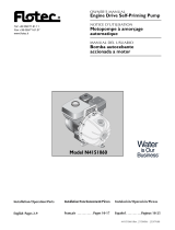
5.1 CONTROL PANEL DESCRIPTION
The control panel is shown in fig. 1
fig.1
Press the START/STOP button to start and/or stop the pump.
5.2 DESCRIPTION OF SIGNALS ON DISPLAY
When running normally (that is, in the absence of any alarms) press the MODE button to alternate the
various displays available:
1. m/PSI Æ Visualizzazione della head
-Current pressure or head, shown in large numbers on the display.
-Currently active set point (dPcn, dPvn or Frqn with n=1 or 2), shown in small numbers on the
display.
-Unit of measurement for pressure or head (PSI))
-Frequency graph indicator.
-Day of the week.
-Master (P) or Slave (S), only for unit configuration.
2. Hz Æ Motor frequency
-Current frequency of the pump in Hz.
-Frequency graph indicator
12
12 - GB -42

Page 13 of 14
-Day of the week.
3. AÆ Absorbed current
-Current absorbed by the pump in Ampere.
-Frequency graph indicator
-Day of the week
4. hh:mm Æ Time
-Time.
-Day of the week.
-Frequency graph indicator
5. Complementary pump status (unit only)
-“STB” the complementary pump is on standby
-“ON “the complementary pump is on and regulating
-“TOP” the complementary pump is on and is at the maximum possible frequency.
-< Alarm Code > the complementary pump is in alarm (for a description of alarm codes, please
see Chpt. 6.0).
The parameter displayed by default is head (m or PSI); after 10 minutes of displaying one of the other
parameters the system automatically returns to displaying pressure.
5.3 PROGRAMMING MENU
Functioning of the module is programmable using a series of parameters grouped into 4 sub-menus:
x The CPS module indicates with the symbol the modification status of the
parameter.
x Press the SET button to save the parameters which have been set and exit the
programming mode.
x Press ESC to exit the programming mode without saving any of the parameters
which have been changed.
Menu Description
Time/day To enter the time and day of the week.
SET-POINT To change the system pressure SET-POINT.
Advanced parameters (Lev.1) To change setting parameters.
Installation parameters (Lev.2) To change system setting parameters.
x For a correct configuration, we recommend using the "installation" and
"advanced" parameters with the machine on STOP and connected to the power
supply.
13
13 - GB - 43

Page 14 of 15
5.3.1 PROGRAMMING CLOCK/DAY
x During the first installation phase, the module display flashes to indicate the internal
clock needs updating.
x The clock is equipped with a battery to maintain the time and date for 24 hours if
there is no power.
MENU DESCR
DISPLAY
PARAMETER
NAME DESCRIPTION DEF MIN MAX
ORA Time Time on system 00:00 00:00 23:59
PROG.
TIME
GIO Day of week Day of week MO MO SU
To modify the time, repeatedly press the “MODE” button until you arrive to the time parameter.
-Press the “SET” button to enter the menu to change the date and hour .
-During the modification of the parameters, the symbol on the display lights up.
-With the buttons it is possible to modify the time.
- Press “MODE” to move onto changing the day .
- With the buttons it is possible to modify the day.
-To save the values press “SET”. The symbol will disappear and the words “REC” will appear
on the screen for a few seconds to show that the data has been saved.
-Press “MODE” to go back to the head screen.
5.3.2 SET POINT
MENU DESCR
DISPLAY
PARAMETER
NAME DESCRIPTION DEFAULT
(m)
MIN
(m)
MAX
(m)
dPc 1
dPv 1
Frq 1
Set Point 1 Main pressure value n n n
dPc 2
dPv 2
Frq 2
Set Point 2 Secondary pressure value (can be set only if the
parameter SET n = 2) n n n
tEP Temperature
function
Value identifying the way in which the set point will
vary based on temperature 5 1 9
Aut AUTO learning
function
Activate or deactivate function OFF OFF ON
SET POINT
In A External
analogue setting
Value identifying the way in which the set point will
vary based on an external analogue signal 5 1 9
To access this menu press and release the SET button (see fig.2):
-During the modification of the set point parameters, the symbol lights up on the display;
-With the buttons it is possible to modify the head or frequency pressure values;
14
14 - GB -44

Page 15 of 16
-press MODE to go from the scroll between menus on the display.
1. TO CHOSE THE TYPE OF CONTROL
Choose the type of control required between constant differential pressure "dPc", proportional
pressure RdPv" or constant frequency "Frq".
2. TO SET THE SET POINT
-SET POINT 1: head or frequency required by the system. The module varies the motor speed to
maintain the system pressure as near as possible to that set. During the regulation of this
parameter, the writing "dPc 1, dPv 1 o Frq 1" appears.
-SET POINT 2: Present only if the module was set to function with two set points (SETn = 2”, see
“ADVANCED PARAMETERS”). When setting this parameter the display shows "dPc 2, dPv 2 o
Frq 2".
If two SET POINTS are present, it is possible to select the one desired using the “S.P.” external contact (see
chapter 3.5) or the internal clock (see Chapter 5.3).
3. tEP TEMPERATURE FUNCTION
The default function is deactivated (tEP=5).
Set tEP<>5 to activate the function and install the optional NTC
temperature sensor. In this case, the set point for the head of the
pump will be reduced or increased based on the temperature of the
water.
If (5<tEP<=9), delivery head for the pump will increase to between
the minimum set value and the set point value.
If (5<tEP<=9), delivery head for the pump will decrease to between
the set point value and the minimum set value.
Decreasing
function selected
Increasing function
selected
Temperature
reference [°C]
1 9 T1=T9=40
2 8 T2=T8=50
3 7 T3=T7=80
4 6 T4=T6=100
4. AUTO ADAP (auto-learning) FUNCTION Aut
The default function is deactivated (OFF).
To activate the function, set the value to ON. If the work point head is less than Hset and the pump is
at maximum speed, the control assumes this value as a set point. After running for approximately 12
hours, the control system will change the status of the hydraulic system increasing the set point by
0.2 m, if necessary.
15
15 - GB - 45

Page 16 of 17
5. ANALOGUE SETTING In A
The default function is deactivated (In A=5).
To activate this function set In A <>5 and install the
potentiometer (as described in Chapter 3.5) or the command
with 0-5V. In this case, the set point for the head of the
pump will be reduced or increased based on the external
signal.
If (5<tEP<=9), delivery head for the pump will increase
between the minimum set value and the maximum value
which can be set as a set point value.
If (5<tEP<=9), delivery head for the pump will decrease
between the maximum set value and the minimum value
which can be set as a set point value.
Press "SET" to confirm. The symbol disappears, the words “REC” will appear on the screen for a few
seconds to show that the data has been saved.
16
16 - GB -46

Page 17 of 18
fig.2
17
17 - GB - 47

Page 18 of 19
5.3.3 ADVANCED PARAMETERS
Key sequence to access the advanced menu
button pressed for 10 seconds
MENU DESCR
DISPLAY
PARAMETER
NAME DESCRIPTION DEFAULT MIN MAX
TPR E Unit of
measurement Pressure unit of measurement m m PSI
SET N
Number of SET
POINTS
Number of set points used 1 1 2
ROT
Motor rotation
direction*
Motor rotation direction POS POS NEG
COR Nominal current* Pump nominal current (read on plate: In) In 1 8
ADVANCED
PARAMETERS
INI Outside contact
setting
Type of inhibitor signal, n.a. (normally open) or
n.c. (normally closed NO NO NC
* Manufacturer's setting.
18
18 - GB -48
Page is loading ...
Page is loading ...
Page is loading ...
Page is loading ...
Page is loading ...
Page is loading ...
Page is loading ...
Page is loading ...
Page is loading ...
Page is loading ...
Page is loading ...
Page is loading ...
-
 1
1
-
 2
2
-
 3
3
-
 4
4
-
 5
5
-
 6
6
-
 7
7
-
 8
8
-
 9
9
-
 10
10
-
 11
11
-
 12
12
-
 13
13
-
 14
14
-
 15
15
-
 16
16
-
 17
17
-
 18
18
-
 19
19
-
 20
20
-
 21
21
-
 22
22
-
 23
23
-
 24
24
-
 25
25
-
 26
26
-
 27
27
-
 28
28
-
 29
29
-
 30
30
-
 31
31
-
 32
32


Pentair Pool Products Nocchi R2CE Use and Maintenance Manual
- Type
- Use and Maintenance Manual
- This manual is also suitable for
Ask a question and I''ll find the answer in the document
Finding information in a document is now easier with AI
Other documents
-
 Chint Power CPS SCE4 Operating instructions
-
Pentair IntelliPro3 VSF Pool Pump User guide
-
 REEFE RPC37001 User manual
-
 Pentair Flotec N4151060 Owner's manual
-
Pentair Maestro User manual
-
Pentair SOLEO CL Installation and User Manual
-
Grundfos UPE Series 2000 Installation And Operating Instructions Manual
-
Pentek Intellidrive PID Owner's manual
-
Grundfos MAGNA 32-100 Installation And Operating Instructions Manual
-
Grundfos Magna 65-120 Installation And Operating Instructions Manual


