Page is loading ...

User Manual
Transporter Mobile DVR

1
Preface
We welcome you as a new user of the world's best digital video recorder (DVR), and the leading
Digital Video Surveillance System. For effective usage, please read this manual carefully. For
future reference, please keep this manual close-at-hand.
Copyright/Authentication/Trademark/Limited Warranty
Copyright
This manual is produced under copyright law. None of its contents may be copied or duplicated
without prior approval.
Copyright 2009~
Authentication
CE, FCC, KCC
Trademark
Ethernet
TM
is the trademark of Xerox Corporation.
Microsoft
TM
, MS-DOS
TM
, Windows
TM
, and Windows NT
TM
are the trademarks of Microsoft
Corporation, used in the United States and elsewhere.
Limited Warranty
The manufacturer, importer, and agent shall not be responsible for accidental damage
(including injury) and other damages caused by inappropriate use or operation of this product.
The information in this manual is prepared based on the current specifications for the product.
The manufacturer is currently adding new functions and will continue to upgrade the product
with new technology. All specifications may be changed without notice to individual users.
Cautions
To operate the product appropriately, we strongly recommend that users read all safety cautions
carefully before operating the product.
Since the indicated cautions contain critical safety information, they must be fully complied with.
The cautions are categorized into the following groups: Danger, Warning, Caution, and Important.
Risk of death or serious injury.
This is the highest priority danger warning.
Risk of serious or lesser degree of injury.
May also cause damage to the product or to property.
Risk of minor injury or damage.
Requirements or limitations regarding operation. Users are
recommended to read the relevant details carefully to operate
the product properly and without harm.
The above cautions indicate the degree of damage that may occur due to inappropriate use of
the system.

2
Risk of death or serious injury.
This is the highest priority danger warning.
• RISK OF EXPLOSION IF BATTERY IS REPLACED BY INCORRECT TYPE. DISPOSE OF USED
BATTERY ACCORDING TO THE INSTRCTIONS.
• THIS EQUIPMENT IS FOR INDOOR-USE, AND ALL THE COMMUNICATION WIRINGS ARE
LIMITED TO INSIDE OF THE BUILDING.
• Please connect the power cord only to the type of AC outlet indicated in the manual or product
specification. If connected to other types of power outlet, fire and electric shock may result.
• Do not expose the product to moisture and dampness. Doing so may result in fire and electric
shock.
• Do not place heavy objects on top of the power cord. Damage to the power cord may result in
fire and electric shock.
• Do not place containers with liquid or small metal objects on top of the product. Liquid or small
metal objects that get inside the unit may lead to fire and electric shock.
• Do not score, bend, twist, pull, or heat the power cord. Damage to the power cord may lead to
fire and electric shock.
• Do not remove the top casing of the product. Doing so may result in electric shock. If internal
examination and maintenance are deemed necessary, contact the authorized system vendors
or installers.
• Do not modify the product in any way. Doing so may lead to fire and electric shock.
• In case of lightning, immediately turn off the power switch and remove the power cord from
the power outlet. Failure to do so may result in fire and electric shock.
• Please use the power cord supplied with the product. Use of other power cords may result in
fire and electric shock.
• In case of smoke, smell, or noise, immediately turn off the power switch and remove the
power cord from the power outlet. Continued operation of the product may result in fire and
electric shock. Request a maintenance service from the authorized system vendors or installers.
• If the product is dropped or damaged, turn off the power switch and remove the power cord
from the power outlet. Continued operation of the product may result in fire and electric shock.
Users should request a maintenance service from the authorized system vendors or installers.
• Do not touch the product with wet hands. Doing so may result in electric shock.
Risk of serious or lesser degree of injury.
May also cause damage to the product or to property.
• Do not leave the power cord or other cables in passageways. Passerbys may trip and fall.
• Avoid contact with water or beverages. Contact with water or beverages may result in
damages that cannot be repaired.
• In case of lightning, immediately turn off the power switch and remove the power cord from
the power outlet. The product may otherwise be damaged.
• Excessive current from the product and the camera may result in an electric shock. Connect
the power cord to an external device only when the products themselves are disconnected
from their power supply.

3
Risk of minor injury or damage.
• If a foreign substance is stuck to the product, use a soft cloth or tissue to remove it. Do not
use chemical agents (thinner, solvent, etc) to remove the substance.
• Do not operate or store the product in the following places:
- An area that is either too cold or too hot
- An area of high humidity or in front of an air-conditioner or places subject to sudden
temperature changes
- An area where there is excessive dust
- Areas where heat from the product cannot be emitted through both of the product's side
ventilation openings
• Do not place credit cards, telephone cards, bank account books, tickets, and other objects with
magnetic properties near the product.
• Static electricity may cause damage to the internal parts of the product. Please remove static
electricity from your body before touching the rear panel and internal electronic parts of the
product.
• If this product is damaged beyond repair or reaches its maximum service life, dispose of it in
compliance with local laws and regulations regarding the disposal of lead and plastic waste.
Requirements or limitations regarding operation. Users are
recommended to read the relevant details carefully to operate
the product properly and without harm.
• The product may not work properly if the power source is unstable and/or if electric shock
occurs. Make sure the correct rated power is available.
• The product is designed to be proof against electric power failures; however, damage may
occur as a result of power failure. Current data may be damaged or data might not be
recorded. Make sure to use an Uninterruptible Power Supply (UPS).
• Since the product is designed to record video data on a hard disk, an error in the hard disk or
other miscellaneous errors might prevent the product from recording properly. Periodic
maintenance is required for proper operation of the product.
• The product is designed for users to configure their own interface. However, a user
configuration error could lead to operation malfunction. This product should be setup by
certified installers only.
• Since the product is connected and tightly coupled to exterior accessories (camera, sensor, LAN,
Hard Disk, etc), there is a risk of malfunction from external causes. Ensure periodic
maintenance by certified installers.
• For installation, use the rack mounting handle provided with the product.
• In this product, 1 Kbyte equals 1,024 bytes; 1 Mbyte equals 1,024,000 bytes; and 1 Gbyte
equals 1,024,000,000 bytes.

4
Contents
Preface ............................................................................................... 1
Copyright/Authentication/Trademark/Limited Warranty ................................................ 1
Cautions ................................................................................................................... 1
Contents ............................................................................................. 4
Chapter 1. Introduction ..................................................................... 6
1. The System ......................................................................................................... 6
2. General Features ................................................................................................ 6
3. Specification ....................................................................................................... 7
Chapter 2. System Installation .......................................................... 8
1. Package Contents ............................................................................................... 8
2. Installation ......................................................................................................... 9
2-1. Bracket Disassembly ........................................................................................... 9
2-2. Unit Installation ................................................................................................ 10
2-3. Connection Devices .......................................................................................... 11
3. Cautions............................................................................................................ 14
Chapter 3. Using DVR ....................................................................... 15
1. Basic Operation ................................................................................................ 15
1-1. Front Panel & IR Remote Controller ................................................................... 15
1-2. Turning on the System ...................................................................................... 17
1-3. Menu Bar ......................................................................................................... 17
1-4. Display Icons ................................................................................................... 18
1-5. User or Admin Login ......................................................................................... 18
1-6. The Main Menu ................................................................................................ 19
1-7. Contextual Menu .............................................................................................. 20
2. DVR Configuration ............................................................................................ 21
2-1. SYSTEM ........................................................................................................... 21
2-1-1. MENU > SYSTEM > Information ............................................................. 21
2-1-2. MENU > SYSTEM > Date & Time ............................................................ 23
2-1-3. MENU > SYSTEM > User ........................................................................ 24
2-1-4. MENU > SYSTEM > Quick Setup ............................................................. 25
2-1-5. MENU > SYSTEM > System Log .............................................................. 25
2-2. DEVICE ............................................................................................................ 26
2-2-1. MENU > DEVICE > Camera .................................................................... 26
2-2-2. MENU > DEVICE > Audio ....................................................................... 27
2-2-3. MENU > DEVICE > Alarm ....................................................................... 27
2-2-4. MENU > DEVICE > Keyboard .................................................................. 28
2-2-5. MENU > DEVICE > RS232 & RS485 ........................................................ 28
2-3. DISPLAY .......................................................................................................... 29
2-3-1. MENU > DISPLAY > Display.................................................................... 29
2-3-2. MENU > DISPLAY > Monitoring .............................................................. 29
2-4. RECORD .......................................................................................................... 30
2-4-1. MENU > RECORD > Storage ................................................................... 30
2-4-2. MENU > RECORD > Record .................................................................... 30
2-4-3. MENU > RECORD > Record Tools ........................................................... 32
2-5. NETWORK ....................................................................................................... 33
2-5-1. MENU > NETWORK > Address ................................................................ 33
2-5-2. MENU > NETWORK > DDNS ................................................................... 33
2-5-3. MENU > NETWORK > Notification .......................................................... 34

5
2-5-4. MENU > NETWORK > Transmission ........................................................ 35
2-6. EVENT ............................................................................................................. 36
2-6-1. MENU > EVENT > Sensor ....................................................................... 36
2-6-2. MENU > EVENT > Motion ....................................................................... 37
2-6-3. MENU > EVENT > Video Loss ................................................................. 39
2-6-4. MENU > EVENT > Text-In ...................................................................... 40
2-6-5. MENU > EVENT > System ...................................................................... 42
2-6-6. MENU > EVENT > G-Sensor ................................................................... 43
3. Playback ........................................................................................................... 44
3-1. Go to Time....................................................................................................... 45
3-2. Calendar Search ............................................................................................... 45
3-3. Event Search .................................................................................................... 46
3-4. Text-In Search .................................................................................................. 46
3-5. Backup Data Playback ...................................................................................... 47
3-6. Playback Control .............................................................................................. 47
4. Backup .............................................................................................................. 48
4-1. Backup ............................................................................................................ 48
4-2. Instant Backup ................................................................................................. 49
4-3. Clip Maker........................................................................................................ 49
Chapter 4. Transporter Viewer ........................................................ 50
1. Using Transporter Viewer ................................................................................. 50
1-1. Starting the Software........................................................................................ 50
1-2. Site Set Up ...................................................................................................... 52
1-3. Favorite Set Up ................................................................................................ 54
1-3. Site List Panel .................................................................................................. 55
1-4. Tool Panel ........................................................................................................ 56
1-4-1. DVR ...................................................................................................... 56
1-4-2. PTZ ....................................................................................................... 56
1-4-3. TEXT-IN ................................................................................................ 57
1-4-4. GPS ....................................................................................................... 57
2. Remote Playback .............................................................................................. 58
2-1. Calendar Search ............................................................................................... 58
2-2. Event Search .................................................................................................... 59
3-3. Text-In Search.................................................................................................. 60
3-4. Saving the Recorded Data ................................................................................. 61
3-5. Play Backup Data ............................................................................................. 62
3-6. Play Independent HDD Data on PC .................................................................... 63
4. Setup ................................................................................................................ 64
4-1. Transporter Viewer Setup .................................................................................. 64
4-2. Remote Setup .................................................................................................. 68
4-3. Remote Upgrade .............................................................................................. 69
5. Transporter Callback ........................................................................................ 70
Appendix A. Remote Access Using Internet Explorer ...................... 72
Appendix B. Setting DDNS Using Router ......................................... 73
1. Domain Name Creation ................................................................................. 73
2. Router Configuration ..................................................................................... 76
3. DVR Configuration ........................................................................................ 77
COMPLIANCE NOTICE OF FCC: ............................................................................. 78
WEEE (Waste Electrical & Electronic Equipment) ................................................. 78
ROHS Compliance ................................................................................................. 78

6
Chapter 1. Introduction
1. The System
The Transporter provides the cutting edge of mobile recording solutions for any type of
transportation security application. This mobile DVR was built upon industrial specification that
offers the most reliable mobile solutions. Its industrial specification allows it to withstand any
harsh conditions of shock, vibration, and temperature. Explore our new Transporter and be
protected by the most reliable in-vehicle device.
2. General Features
• Advanced H.264 Linux Embedded DVR
• Live View, Remote Playback, File Backup, E-mail Notification
• 30fps @ D1, 120fps @ CIF
• 4 Channel Video / 4 Channel Audio Recording
• G-Sensor Technology
• GPS Driven by Google Map
• Wireless Communication Access Any Transporter Via External Wireless Bridge or Wireless
Mobile Router
• Central Management Software up to 64 Channels
• Support Blackberry, iPhone, and 3G Phone
• 3 Year Limited Warranty

7
3. Specification
Model
Transporter
Video
In
4 Channel
Out
1 CVBS
Audio
In
4 Mic-In
Out
1 Line-Out
Device
Sensor In
2 TTL
Alarm Out
2 Relay
I/O Interface
RS232, RS485, USB2.0 x 1, USB1.1 x 1 for Mouse
Display
Speed
Real Time
Resolution
720 x 480 (NTSC), 720 x 576 (PAL)
Split Screen
1, 4, PIP, Digital Zoom
Recording
Compression
H.264 Codec
Speed /
Resolution
120fps@CIF (NTSC)
100fps@CIF (PAL)
60fps@Half D1 (NTSC)
50fps@Half D1 (PAL)
30fps@D1 (NTSC)
25fps@D1 (PAL)
Picture Quality
Very High, High, Standard, Low
Mode
Time-Lapse, Event, Time & Event
Playback
Display
1, 4, Digital Zoom
Search Mode
Calendar Search, Event Search, Text-In Search, Go to Time
Playback Mode
Multi-Channel Normal & Reverse Play,
RW & FF (x2, x4, x8, x16, x32), Frame to Frame, Pause
Map
Associated Google Map
Network
Interface
Ethernet (10/100 Base)
Protocol
TCP/IP, HTTP, DHCP, ADSL (PPPoE)
Application
Live, Playback, Setup, Notification (Callback, E-Mail)
Web Browser
Internet Explorer 7 or Higher
Storage
Removable Rack (2.5” SATA HDD, SSD, & SD Card)
Backup
External HDD, USB Memory
Control
USB Mouse,
IR Remote Controller, Joystick Controller
OSD
Graphic User Interface (Multilingual)
Approval
FCC, CE, KCC
RoHS
RoHS Compliance
Power Consumption
DC12V~36V, Max 64W
Operating Temperature
-20°C ~ 50°C / -4°F~122°F (Built-In Heating System)
Operating Humidity
0%~80% / Non-Condensing
Dimension
225.5(W) x 59(H) x 245.2(D) mm
8.87(W) x 2.32(H) x 9.65(D) inch
Weight
1.63 kg / 3.6 lbs (with 250G HDD)

8
Chapter 2. System Installation
1. Package Contents
The following components are included in the product:
DVR Unit
Harness & Terminal Block
Monitor Cable
Power Cable
Remote Controller
CD
(User Manual & Network S/W)
Quick Guide
Bracket Screws & Keys
GPS Antenna

9
2. Installation
2-1. Bracket Disassembly
Take the unit out of the box and disassemble the brackets as follow:
- Unscrew Rear Cover Screws to remove Rear Cover.
- Unscrew Bracket Screws to remove Installation (bottom) Bracket.
- The installation bracket has the following size, and it must be bolted down on the bottom
or top surface strongly using the 6 Bracket Screws.
Rear Cover
Rear Cover Screws (3 points)
Bracket Screws (6 points)

10
2-2. Unit Installation
Bolt down Installation Bracket on the bottom or top surface, using the six Bracket Screws.
- To install the unit on the bottom, just use the bracket screws to bolt down the unit with
the installation bracket.
- To install the unit on the top, turn the installation bracket upside down and bolt the unit
with the installation bracket.
Note
: Please do not install DVR as shown below. Inappropriate installation of DVR will affect HDD‟s stability or
operation.
[The Bottom]
[The Top]
Bracket Screws (6 points)

11
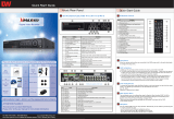
2-3. Connection Devices
The front and rear panel of the Transporter comprise of the following:
• Front USB: Two USB ports are provided to connect external devices like HDD, USB Flash Drive
for Backup and System Upgrade, or USB Mouse on the front panel. A USB Mouse can be
connected only to the bottom USB port on the front panel. The specific USB port is only for the
mouse.
Note
: Before connection the cables/connectors, make sure they are all through the Rear Cover Hole. Lock the
Rear Cover for easy arrangement.
Video/Audio Input, Camera Power Output
The unit has four groups of Video Input(VI), Audio Input(AI), and Camera Power Output(PO) as
shown above. Use the 24 Pin Connector included in the box to connect cameras.

12
Monitor Output
The connector for CVBS (NTSC or PAL) monitor. VO refers to Video Out, and AO refers to Audio
Out. The Monitor power (12V) needs to be connected to PO. G (Ground) Pin is general for all
outputs. 12V Monitor power is only supportable for a maximum 7” LCD monitor (TX/RX is not in
any usage on this unit).
Notice
: The total 12V/1.6A supports 4 cameras and 1 monitor.
Power In
The DVR will operate on both 12V and 24V systems. Pins 1 and 2 should be connected directly to
the positive (+) battery. Pin 3 should be connected to the positive (+) power bus bar that is
turned on when the ignition switch is in the Accessory position. Pin 4 should be connected
directly to ground.
I/O Terminal Block
• RS232C: An RS232C Connector is provided to connect external devices such as ATM or POS
machine for Text-In function.
• RS485: The RS485 Connector can be used to connect PTZ cameras. Transporter can also be
controlled remotely by a control keyboard.
• Alarm: Alarm output connectors are provided to connect external alarms, such as sirens or
lights. Two alarm output connectors have internal relays.
• Sensor: Two sensor input connectors are provided to connect external devices. You can use
sensors to signal the DVR with event.

13
Network Port
Connect a Cat5 Cable with an RJ45 Connector to the DVR for remote
monitoring, remote playback, and remote setup. See
Chapter 3-2. DVR
Configuration
for configuring the Network connections.
3G (GPRS) Router can be used for the wireless network connection.
Connect 3G (GPRS) Router on the network port. For a detail usage of 3G
(GPRS) Router, please contact your service provider of 3G networks or
your 3G (GPRS) Router Manual.
ETC
• GPS Antenna: The unit has built in GPS. SMA type GPS antenna needs to be set up
separately for the proper reception of GPS data.
• Reset: The DVR has a Reset switch that will only be used to return all the settings to the
original factory settings. To reset the unit, turn the DVR off first. Turn it on again while poking
the straightened paperclip in the reset hole. Hold the switch until the DVR is initializing.

14
3. Cautions
• Avoid installing the product near direct sun rays or near a heat generator. The excessive heat
may cause fire.
• Do not place a vase, flowerpot, cup, cosmetics, drug, or any product that may contain water. It
may cause fire or electric shock, and it may injure people by falling.
• Do not insert or drop any metal object (coin, hair pin, etc) or flammable object (match, paper,
etc) into the air hole. It may cause fire or electric shock.
• Do not place any heavy object on your product. It may injure people or get destroyed when
knocked down.
• Put power plug in a place where it will not be moved. If not, it can cause fire.
• Unplug power plug and antenna, when there are thunders and lightening. If not, it may cause
fire.
• To clean the product, wipe surface with dry towel. Using chemical agent or cleaner may
change the color and unpeel paint.
• Do not plug several plugs at same time. It may cause electric shock.
• If there is smoke or a strange smell, stop the operation. In this case, turn the power off and
unplug it, and then contact our service center. Continuous use of the product may lead to fire
or electric shock.
• Do not unplug by pulling the cord. If cord is damaged, it may cause fire or electric shock.
• Do not plug or unplug with wet hands. It may cause electric shock.
• Keep the power cord untwisted. It may cause fire or electric shock.
• Use proper adapter. Using too much electric power may cause fire or electric shock.
• Do not install it where it is exposed to rain, wind and water drops. It may cause fire, electric
shock, and/or transformation.
• Keep away from fire.
• Do not disassemble or remodel on your own. It may cause malfunction or electric shock.
• Do not put next to flammable materials, like flammable spray. It may cause fire.
• Do not install it in a place with too much dirt. It may cause fire.
• Do not install it on unstable places like a shaking table, an inclined plane, or a shaking place. It
may injure users by falling down.
• Do not place a heavy object on the power cord or avoid it from being pressed by the device. It
may cause fire or electric shock.
• In case of using extension cord, do not use several devices at same time. It may cause fire
with abnormal heating of the extension.
• When there is dirt on the power plug pin or power outlet, clean it nicely. It may cause fire.
• Do not damage on power cord by plugging, bending, twisting, pulling, or placing it between
other objects or heat. If power outlet insertion part is not tight, do not use it. It may cause fire
or electric shock.
• Do not drop or shock the product. It may injure people or cause malfunction.
• Do not touch power adaptor or signal controller. It may cause electric shock.
• Do not place an object too close to the cooling fan. It may cause fire.
• Exchanging batteries with an improper type can cause an explosion.
• For used batteries, throw away separately from other garbage.
• When you take out batteries, keep them away from children. Avoid children from consuming
the battery by mistake. If a child accidentally eats a battery, contact a doctor right away.

15
Chapter 3. Using DVR
1. Basic Operation
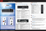
1-1. Front Panel & IR Remote Controller
Front Panel
Description
USB Port
Two USB ports are located on the front panel. As directed in
the picture, a USB mouse can be connected to the USB port
dedicated only for the mouse.
Status LED
Power HDD Alarm
> > : Indicates Normal system booting
Blink: Indicates Front Cover is not closed properly
On/ Blink: Indicates the heater is on due to low
temperature and needs to wait until it reaches operating
temperature level.
Lock Key
Use the key included in the box to open the door and install or
uninstall the HDD rack. To remove the HDD rack while the
system is running, open the door and wait for about 10
seconds until the Power LED starts flickering for the safe
removal of HDD rack.
Remote Control Button
Description
Camera Buttons (1~0)
Pressing camera buttons and Enter button will cause the
selected camera to display full screen. Buttons are used to
enter passwords.
MENU / EXIT Button
Enter the Setup Menu. User will need to enter the authorized
password to assess Setup. In Playback mode, MENU button
displays the Playback Menu.
DISPLAY Button
Change the screen display mode in the current screen or
playback screen.
SEQUENCE Button
Display live channels sequentially.

16
Up, Down, Left, Right
Arrow, ENTER Buttons
Change settings for the product in MENU mode or in PTZ
control mode.
BACKUP Button
Copy recorded data to an external storage device.
PLAYBACK Button
Change to playback mode from live mode.
PAUSE Button
Under playback mode, the button can be used to pause the
playback screen.
Display menu to save PTZ preset under PTZ mode.
PLAY Button
Play the video forward. Press the button repeatedly to
increase play speed up to max 32 times (1, 2, 4, 8, 16, 32
times) faster. Use this button to move right when setting the
menu.
Focus on far distance under PTZ mode.
R.PLAY Button
Play the video backward. Press the button repeatedly to
increase play speed up to max 32 times (1, 2, 4, 8, 16, 32
times) faster. Use this button to move right when setting the
menu.
Zoom Out under PTZ mode.
STEP FORWARD Button
Move forward by one frame under Pause. Use this button to
move up when setting the menu.
Zoom Out under PTZ mode.
STEP BACKWARD Button
Move backward by one frame under Pause. Use this button to
move down when setting the menu.
Zoom In under PTZ mode.
PTZ Button
Change to PTZ control mode from live mode.
ZOOM Button
Magnify the current image on the screen.
PIP Button
Change to PIP screen mode from live screen.
AUDIO Button
Select a camera for live & playback audio output.
OSD Button
Turn On/Off the OSD Display.
LOG Button
Check the system log information.
ID Button
Select the DVR system ID. (Remote controller Only)
E.REC Button
Pressing the E.REC button starts Emergency Recording Mode
of all camera channels and displays "!" on the screen. Pressing
the button again will stop E.REC Mode.

17
1-2. Turning on the System
If it is installed properly, the unit will start and run automatically when the ignition is turned on. It
will take about 20-30 seconds for the boot up and start recording based on the pre-setup options.
If the temperature is below -0°C (32°F), the unit will start recording after HDD is heated by our
built-in heating sensor.
If SD card is installed with HDD, it will start recording on SD Card while HDD is being heated.
Once HDD is ready to record the data, it will stop the recording on SD and automatically start
recording data on HDD.
The unit will stop recording automatically once the ignition is turned off. The unit only runs while
the ignition is on.
Note
: The HDD Rack can be removed and played on PC. However, it is recommended to remove the HDD Rack
once the unit is turned off safely. To remove the HDD rack while the system is running, open the door and wait
for about 10 seconds until the Power LED starts flickering for the safe removal of HDD rack.
Note
: When installing the HDD for the first time, the HDD should be formatted first.
“MENU > RECORD > Storage > HDD Format”
1-3. Menu Bar
The menu bar will appear on the bottom of the screen as shown below.
Pressing the Menu will bring up the main menu list.
Shows the percentage of HDD being used.
Turns on when the HDD is set to be overwritten.
Receiving GPS data
Turns on when the system is connected to the network.
Turns on when the Alarm is being activated.
G-Sensor is detected.
E.REC (Emergency Recording) Mode
Displays date & time.
IR Remote Controller

18
1-4. Display Icons
No Recording
Recording (Red)
E.REC (Emergency Recording)
Event Recording (Red)
Pre-Event Recording (Blue)
Motion Detection
Sensor Detection
Text-In
PTZ Camera
Instant Backup
Clip Maker (Blue)
Backup (Red)
Video Loss
1-5. User or Admin Login
Press MENU to enter main menu screen. Login screen appears for you to enter ID (Administrator
or User) and Password. Password can consist of up to 8 numbers by the combination of numbers
from 0 to 9.
The factory default password is „none‟ so press OK to login to the system for the first time.
Password can be set under password setup option (
MENU > SYSTEM > User
).
The system will automatically logout, if it is not in-use for a certain period of time. This "Auto
Logout Time" can be set under password set up option (
MENU > SYSTEM > User
).

19
1-6. The Main Menu
The Main Menu of DVR consists of SYSTEM, DEVICE, DISPLAY, RECORD, NETWORK, and EVENT.
Each menu consists of various sub-menus that allow detail set up of the system. Use Mouse,
Remote Controller, or Front Buttons for access to each menu.
Note
: To prevent any unauthorized changes of system settings or operations, please make sure the system
logout is done when the system setting or operation is completed.
MAIN MENU
SYSTEM
Information
Date & Time
User
Quick Setup
System Log
DEVICE
Camera
Audio
Alarm
Keyboard
RS232 & RS485
DISPLAY
Display
Monitoring
RECORD
Storage
Record
Record Tools
NETWORK
Address
DDNS
Notification
Transmission
EVENT
Sensor
Motion
Video Loss
Text-In
System
G-Sensor
LOGOUT
SHUTDOWN
/