AFi RRM-30 Owner's manual
- Category
- Security device components
- Type
- Owner's manual
This manual is also suitable for

© Copyright 2005, American Fibertek, Inc. 0627JD
Instruction Manual
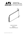
RRM-33
Three Video Receivers

2
INSTALLATION AND OPERATION INSTRUCTIONS
INTRODUCTION
Thank you for purchasing your American Fibertek RRM-33, which consists of three
multimode video receivers. Please take a few minutes to read these installation
instructions in order to obtain the maximum performance from this product.
FUNCTIONAL DESCRIPTION
The RRM-33 operates as half of a transmitter / receiver pair for the transmission of
three baseband NTSC, PAL, RS170, or RS343 video signals over three strands of
multimode fiber optic cable. Each of its three independent optical inputs is designed to
operate with the MTM-300, RTM-300, or RTM-33 video transmitter. The RRM-33
contains the electronics and optics of three RRM-300 units mounted on one printed
circuit board to save space and reduce cost.
The RRM-33 converts three FM modulated optical inputs into three separate video
outputs using a 1300 nm wavelength detector for each signal. The M33 Series product
is designed to operate over an optical loss budget range of 0 to 12 dB. The RRM-33
operates on 50 um or 62.5 um multimode fiber. Refer to the data sheets for detailed
performance specifications.
This unit is designed for rack mounting in any of the three American Fibertek subracks
available. The subrack model numbers are SR-20/1, SR-20R/1, and SR-20/2. Slide in
rack mounting and a LED indicator provide for easy installation and monitoring of video
and power.
The RRM-33 is designed for rack mounting only. For a single channel modular stand
alone version please see the MRM-300.

3
INSTALLATION
THIS INSTALLATION SHOULD BE MADE BY A QUALIFIED SERVICE PERSON AND
SHOULD CONFORM TO THE NATIONAL ELECTRICAL CODE, ANSI/NFPA 70 AND
LOCAL CODES.
The unit slides into any open slot in the SR-20 subrack. Use a small screwdriver to push
and lock the two ¼ turn fasteners into place. Please note that when installing this card in
the position directly next to the power supply in the SR-20 subrack, it may be necessary
to make the signal connections at the rear of the card before fully seating the card into
its slot.
POWER SOURCE
Power to the unit is supplied by the subrack. Please refer to the SR-20 and PSR
instructions for further details.
POWER CONNECTION
Power is supplied to the unit via a four finger backplane connector. The RRM-33 can be
inserted into the subrack or removed from the subrack with power applied to the
backplane.
INPUT / OUTPUT CONNECTIONS
Fiber optic connections are made via ST connectors located on the back of the unit. Be
sure to allow sufficient room for the required minimum bend radius of the fiber cable
used.
Video output connections are made via BNC connectors on the back of the unit. The
75Ω video outputs can be looped through typical baseband video inputs of switchers,
recorders and other equipment as required. For proper operation, the outputs must be
terminated with 75Ω. For optimum performance the video cables should be the shortest
length of coax practical.

4
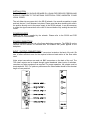
RRM-33 STATUS INDICATORS
The RRM-33 receiver provides the following LED status indicators to aid in installation
and troubleshooting:
OLI 1 THROUGH OLI 3
A bi-color LED indicator monitors the power of each of the optical signals that is being
received at the RRM-33 from the MTM-300, RTM-300, or RTM-33. DC power and
optical input status associated with this LED is summarized below.
Optical Level Indicator DC Power Status Optical Status
Green On Proper Optical Input Power Present
Red On Optical Input Not Detected
Off Off Check Power Supply
LIFETIME WARRANTY INFORMATION
American Fibertek, Inc warrants that at the time of delivery the products delivered will be
free of defects in materials and workmanship. Defective products will be repaired or
replaced at the exclusive option of American Fibertek. A Return Material Authorization
(RMA) number is required to send the products back in case of return. All returns must
be shipped prepaid. This warranty is void if the products have been tampered with. This
warranty shall be construed in accordance with New Jersey law and the courts of New
Jersey shall have exclusive jurisdiction over this contract. EXCEPT FOR THE
FOREGOING WARRANTY, THERE IS NO WARRANTY OF MERCHANTABILITY OR
FITNESS FOR A PARTICULAR PURPOSE OR OTHERWISE, EXPRESSED OR
IMPLIED, WHICH EXTENDS BEYOND THE WARRANTY SET FORTH IN THIS
AGREEMENT. In any event, American Fibertek will not be responsible or liable for
contingent, consequential, or incidental damages. No agreement or understanding,
expressed or implied, except as set forth in this warranty, will be binding upon American
Fibertek unless in writing, signed by a duly authorized officer of American Fibertek.
SERVICE INFORMATION
There are no user serviceable parts inside the unit.
In the event that service is required to this unit, please direct all inquiries to:
American Fibertek, Inc. Phone: (877) 234-7200
120 Belmont Drive Phone: (732) 302-0660
Somerset, NJ 08873 FAX (732) 302-0667
E-mail: techinfo@americanfibertek.com
-
 1
1
-
 2
2
-
 3
3
-
 4
4


AFi RRM-30 Owner's manual
- Category
- Security device components
- Type
- Owner's manual
- This manual is also suitable for
Ask a question and I''ll find the answer in the document
Finding information in a document is now easier with AI
Related papers
Other documents
-
American Fibertek MRM-100 User manual
-
FiberHome AN6000-15 Installation guide
-
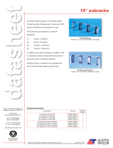 Austin Taylor 9RAC193818 Datasheet
-
Mipro MRM-70B (6C) User manual
-
Orbegozo RRM 510 A User manual
-
Mipro MA-808PADM (6A) Owner's manual
-
Huawei OptiX OSN 2500 Quick Installation Manual
-
ZTE ZXSDR BS8900 User manual
-
MSA Z-Gard® CXII Controller Owner's manual
