ATEN CE250a is a KVM (Keyboard, Video, Mouse) Extender that allows you to control a computer from up to 164 feet (50 meters) away. This can be useful in a variety of scenarios, such as:
- Placing the computer in a secure or environmentally controlled location, while still being able to access it from a remote location.
- Extending the reach of your KVM signal to a remote monitor or projector.
- Creating a multi-user workstation, where multiple users can share a single computer. The CE250a is a high-performance KVM extender that supports resolutions up to 1920 x 1200 at 60Hz. It also features:
- 2-port USB hub for connecting peripherals such as printers, scanners, and external storage drives.

KVM Extender
CE250A
User Manual
www.aten.com

CE250A User Manual
ii
EMC Information
FEDERAL COMMUNICATIONS COMMISSION INTERFERENCE
STATEMENT: This equipment has been tested and found to comply with the
limits for a Class A digital device, pursuant to Part 15 of the FCC Rules. These
limits are designed to provide reasonable protection against harmful
interference when the equipment is operated in a commercial environment.
This equipment generates, uses, and can radiate radio frequency energy and, if
not installed and used in accordance with the instruction manual, may cause
harmful interference to radio communications. Operation of this equipment in
a residential area is likely to cause harmful interference in which case the user
will be required to correct the interference at his own expense.
The device complies with Part 15 of the FCC Rules. Operation is subject to the
following two conditions: (1) this device may not cause harmful interference,
and (2) this device must accept any interference received, including
interference that may cause undesired operation.
FCC Caution: Any changes or modifications not expressly approved by the
party responsible for compliance could void the user's authority to operate this
equipment.
CE Warning: This is a class A product. In a domestic environment this
product may cause radio interference in which case the user may be required to
take adequate precautions.
Suggestion: Shielded twisted pair (STP) cables must be used with the unit to
ensure compliance with FCC & CE standards.
KCC Statement
유선 제품용 / A 급 기기 ( 업무용 방송 통신 기기 )
이 기기는 업무용 (A 급 )전자파적합기기로서 판매자 또는 사용자는 이
점을 주의하시기 바라며 ,가정 외의 지역에서 사용하는 것을 목적으로
합니다 .
RoHS
This product is RoHS compliant.

CE250A User Manual
iii
SJ/T 11364-2006
The following contains information that relates to China.

CE250A User Manual
iv
User Information
Online Registration
Be sure to register your product at our online support center:
Telephone Support
For telephone support, call this number:
User Notice
All information, documentation, and specifications contained in this manual
are subject to change without prior notification by the manufacturer. The
manufacturer makes no representations or warranties, either expressed or
implied, with respect to the contents hereof and specifically disclaims any
warranties as to merchantability or fitness for any particular purpose. Any of
the manufacturer's software described in this manual is sold or licensed as is.
Should the programs prove defective following their purchase, the buyer (and
not the manufacturer, its distributor, or its dealer), assumes the entire cost of all
necessary servicing, repair and any incidental or consequential damages
resulting from any defect in the software.
The manufacturer of this system is not responsible for any radio and/or TV
interference caused by unauthorized modifications to this device. It is the
responsibility of the user to correct such interference.
The manufacturer is not responsible for any damage incurred in the operation
of this system if the correct operational voltage setting was not selected prior
to operation. PLEASE VERIFY THAT THE VOLTAGE SETTING IS
CORRECT BEFORE USE.
International http://support.aten.com
North America http://www.aten-usa.com/product_registration
International 886-2-8692-6959
China 86-10-5255-0110
Japan 81-3-5615-5811
Korea 82-2-467-6789
North America 1-888-999-ATEN ext 4988
United Kingdom 44-8-4481-58923

CE250A User Manual
v
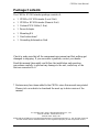
Package Contents
The CE250A KVM Extender package consists of:
1 CE250
AL KVM Extender (Local Unit)
1 CE250
AR KVM Extender (Remote Unit)
1 Custom KVM Cable (1.8 m)
1 Power Adapter
1 Mounting Kit
1 User Instructions*
1 Grounding Information Card
Check to make sure that all the components are present and that nothing got
damaged in shipping. If you encounter a problem, contact your dealer.
Read this manual thoroughly and follow the installation and operation
procedures carefully to prevent any damage to the unit, and/or any of the
devices connected to it.
* Features may have been added to the CE250A since this manual was printed.
Please visit our website to download the most up-to-date version of the
manual.
© Copyright 2007–2015 ATEN® International Co., Ltd.
Manual Part No. PAPE-0222-AT3G
Manual Date: 2015-4-30
ATEN and the ATEN logo are registered trademarks of ATEN International Co., Ltd. All rights reserved.
All other brand names and trademarks are the registered property of their respective owners.

CE250A User Manual
vi
Contents
EMC Information. . . . . . . . . . . . . . . . . . . . . . . . . . . . . . . . . . . . . . . . . . . . . ii
RoHS . . . . . . . . . . . . . . . . . . . . . . . . . . . . . . . . . . . . . . . . . . . . . . . . . . . . . ii
SJ/T 11364-2006 . . . . . . . . . . . . . . . . . . . . . . . . . . . . . . . . . . . . . . . . . . . .iii
User Information. . . . . . . . . . . . . . . . . . . . . . . . . . . . . . . . . . . . . . . . . . . . .iv
Online Registration . . . . . . . . . . . . . . . . . . . . . . . . . . . . . . . . . . . . . . . .iv
Telephone Support . . . . . . . . . . . . . . . . . . . . . . . . . . . . . . . . . . . . . . . .iv
User Notice . . . . . . . . . . . . . . . . . . . . . . . . . . . . . . . . . . . . . . . . . . . . . .iv
Package Contents . . . . . . . . . . . . . . . . . . . . . . . . . . . . . . . . . . . . . . . . . . . v
Contents . . . . . . . . . . . . . . . . . . . . . . . . . . . . . . . . . . . . . . . . . . . . . . . . . . .vi
About this Manual. . . . . . . . . . . . . . . . . . . . . . . . . . . . . . . . . . . . . . . . . . .viii
Conventions . . . . . . . . . . . . . . . . . . . . . . . . . . . . . . . . . . . . . . . . . . . . . . . .ix
Product Information . . . . . . . . . . . . . . . . . . . . . . . . . . . . . . . . . . . . . . . . . .ix
Chapter 1.
Introduction
Overview. . . . . . . . . . . . . . . . . . . . . . . . . . . . . . . . . . . . . . . . . . . . . . . . . . .1
Features . . . . . . . . . . . . . . . . . . . . . . . . . . . . . . . . . . . . . . . . . . . . . . . . . . .2
Requirements . . . . . . . . . . . . . . . . . . . . . . . . . . . . . . . . . . . . . . . . . . . . . . .3
Console. . . . . . . . . . . . . . . . . . . . . . . . . . . . . . . . . . . . . . . . . . . . . . . . .3
Computers. . . . . . . . . . . . . . . . . . . . . . . . . . . . . . . . . . . . . . . . . . . . . . .3
Cables. . . . . . . . . . . . . . . . . . . . . . . . . . . . . . . . . . . . . . . . . . . . . . . . . .3
Operating Systems. . . . . . . . . . . . . . . . . . . . . . . . . . . . . . . . . . . . . . . . . . . 4
OS Languages . . . . . . . . . . . . . . . . . . . . . . . . . . . . . . . . . . . . . . . . . . . 4
Components . . . . . . . . . . . . . . . . . . . . . . . . . . . . . . . . . . . . . . . . . . . . . . . .5
CE250AL (Local Unit) Front View. . . . . . . . . . . . . . . . . . . . . . . . . . . . .5
CE250AR (Remote Unit) Front View. . . . . . . . . . . . . . . . . . . . . . . . . . . 6
CE250AL / CE250AR Rear View . . . . . . . . . . . . . . . . . . . . . . . . . . . . .7
Chapter 2.
Hardware Setup
Rack Mounting . . . . . . . . . . . . . . . . . . . . . . . . . . . . . . . . . . . . . . . . . . . . . .9
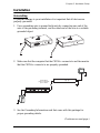
Installation. . . . . . . . . . . . . . . . . . . . . . . . . . . . . . . . . . . . . . . . . . . . . . . . .11
Grounding . . . . . . . . . . . . . . . . . . . . . . . . . . . . . . . . . . . . . . . . . . . . . . 11
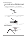
Connecting Up . . . . . . . . . . . . . . . . . . . . . . . . . . . . . . . . . . . . . . . . . .13
Chapter 3.
Operation
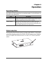
Operating Modes . . . . . . . . . . . . . . . . . . . . . . . . . . . . . . . . . . . . . . . . . . . 15
Mode Selection. . . . . . . . . . . . . . . . . . . . . . . . . . . . . . . . . . . . . . . . . . . . .15
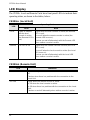
LED Display . . . . . . . . . . . . . . . . . . . . . . . . . . . . . . . . . . . . . . . . . . . . . . .16
CE250AL (Local Unit) . . . . . . . . . . . . . . . . . . . . . . . . . . . . . . . . . . . . .16
CE250AR (Remote Unit). . . . . . . . . . . . . . . . . . . . . . . . . . . . . . . . . . . 16

CE250A User Manual
vii
Appendix
Safety Instructions. . . . . . . . . . . . . . . . . . . . . . . . . . . . . . . . . . . . . . . . . . .17
General . . . . . . . . . . . . . . . . . . . . . . . . . . . . . . . . . . . . . . . . . . . . . . . .17
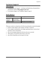
Technical Support. . . . . . . . . . . . . . . . . . . . . . . . . . . . . . . . . . . . . . . . . . .19
International. . . . . . . . . . . . . . . . . . . . . . . . . . . . . . . . . . . . . . . . . . . . .19
North America . . . . . . . . . . . . . . . . . . . . . . . . . . . . . . . . . . . . . . . . . . .19
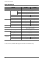
Specifications . . . . . . . . . . . . . . . . . . . . . . . . . . . . . . . . . . . . . . . . . . . . . .20
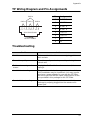
TP Wiring Diagram and Pin Assignments. . . . . . . . . . . . . . . . . . . . . . . . .21
Troubleshooting . . . . . . . . . . . . . . . . . . . . . . . . . . . . . . . . . . . . . . . . . . . .21
Limited Warranty. . . . . . . . . . . . . . . . . . . . . . . . . . . . . . . . . . . . . . . . . . . .22

CE250A User Manual
viii
About this Manual
This User Manual is provided to help you get the most from your system. It
covers all aspects of installation, configuration and operation. An overview of
the information found in the manual is provided below.
Chapter 1, Introduction, introduces you to the CE250
A system. Its
purpose, features and benefits are presented, and its front and back panel
components are described.
Chapter 2, Hardware Setup, describes how to set up your installation.
Chapter 3, Operation, explains the fundamental concepts involved in
operating the CE250
A.
An Appendix, provides specifications and other technical information
regarding the CE250
A.

CE250A User Manual
ix
Conventions
This manual uses the following conventions:
Product Information
For information about all ATEN products and how they can help you connect
without limits, visit ATEN on the Web or contact an ATEN Authorized
Reseller. Visit ATEN on the Web for a list of locations and telephone numbers:
Monospaced Indicates text that you should key in.
[ ] Indicates keys you should press. For example, [Enter] means to
press the Enter key. If keys need to be chorded, they appear
together in the same bracket with a plus sign between them:
[Ctrl+Alt].
1. Numbered lists represent procedures with sequential steps.
♦ Bullet lists provide information, but do not involve sequential steps.
→ Indicates selecting the option (on a menu or dialog box, for
example), that comes next. For example, Start
→ Run means to
open the Start menu, and then select Run.
Indicates critical information.
International http://www.aten.com
North America http://www.aten-usa.com

CE250A User Manual
x
This Page Intentionally Left Blank

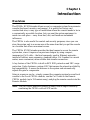
1
Chapter 1
Introduction
Overview
The CE250A KVM Extender allows access to a computer system from a remote
console (keyboard, monitor, and mouse). It is perfect for factory and
construction sites, or any type of installation where the console needs to be in
a conveniently accessible location, but you want the system equipment to
reside in a safe place – away from dust, dirt, and harsh environmental
influences.
The CE250
A is also useful for control and security purposes, since you can
store the system unit in a secure area at the same time that you put the console
in a location that offers convenient access.
The CE250
A KVM Extender provides the ideal means to access the remote
system box, since it improves on previous designs by using compact,
inexpensive Cat 5 cable – the kind commonly used in Ethernet networks –
instead of bulkier, more expensive, standard cables. Cat 5 makes for a much
neater, more convenient, more reliable data transfer connection.
A key feature of the CE250
A is built-in 8KV ESD protection and 2KV surge
protection. It also features a custom ASIC that ensures the utmost in reliability
and compatibility. It senses the distance to the system and automatically
adjusts the gain to compensate.
Setup is as easy as can be – simply connect the computer system box and local
console to the Local CE250
A module, run the Cat 5 cable to the Remote
CE250
A module (up to 150 meters away); and plug the remote console into the
Remote Module.
Note: You can control numerous remote systems from a single console by
combining the CE250A with a KVM switch.

CE250A User Manual
2
Features
Cat 5 (or higher) cable to connect the Local and Remote Units – up to 150
m apart
Dual console operation – control your system from both the local and
remote PS/2 keyboard, mouse and monitor consoles
Pushbutton selection of the active console
High resolution video – up to 1280 x 1024 @ 60 Hz
Supports VGA, SVGA, and Multisync monitors – local monitor supports
DDC; DDC2; DDC2B
Supports Microsoft Intellimouse and the scrolling wheel on most mice
Automatic gain control – automatically adjusts signal strength to
compensate for distance
Built-in 8KV ESD protection and 2KV surge protection
Built-in ASIC for greater reliability and compatibility
Local unit takes its power from the computer – external power is only
required when the power from the local computer/computers in the KVM
installation is insufficient*
Rack mountable
Supports Wide Screen formats **
Note: *If you choose to purchase a power adapter for use with the CE250AL,
be sure to get one with the same specifications as the one provided in
this package for the CE250
AR.
**The EDID data for a widescreen is sent from the local video output
port. For widescreen modes and displays connect the monitor to the
local video output port or use an ATEN EDID emulator.

Chapter 1. Introduction
3
Requirements
Console
A VGA, SVGA, or Multisync monitor capable of the highest resolution
that you will be using on any computer in the installation
A PS/2 keyboard
A PS/2 mouse
Note: 1. If you connect a DDC type monitor to the Local Unit, the monitor that
connects to the Remote Unit must be able to support the highest video
resolution that the DDC monitor can provide.
2. You must use the same brand and model of mouse on both the local
and remote units.
Computers
The following equipment must be installed on each computer that is to be
connected to the system:
A VGA, SVGA, or Multisync card
A 6-pin mini-DIN mouse port
A 6-pin mini-DIN keyboard port
Cables
For optimum signal integrity we strongly recommend that you use the
high-quality Custom KVM cable provided with this package. The shape
and function of the KVM connectors on the switch and the cable have
been modified so that only KVM cables designed to work with this KVM
switch can be used.
Cat 5 cable is the minimum required to connect the local and remote
CE250
A units.

CE250A User Manual
4
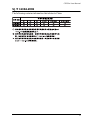
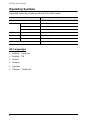
Operating Systems
Supported operating systems are shown in the table, below:
OS Languages
English – American
English – UK
French
German
Japanese
Chinese – Traditional
OS Version
Windows 2000 and higher
Linux RedHat 7.1 and higher
SuSE 9.0 and higher
Mandriva (Mandrake) 9.0 and higher
UNIX AIX 4.3, 5L (5.2, 5.3)
FreeBSD 4.2, 4.5
Novell Netware 6.0 and higher
OS/2 Warp and higher

Chapter 1. Introduction
5
Components
CE250AL (Local Unit) Front View
Note: If you are combining the CE250A with a KVM switch, the KVM cable
connects to the respective ports on the Console section of the switch.
# Description Function
1 Grounding
Ter mina l
The grounding wire (used to ground the unit) attaches here.
2 KVM Port The KVM cable that links the CE250
AL to your computer
plugs in here. Only KVM cables designed to work with this
switch can be used.*
3 Remote LED The Local Unit has two LEDs to indicate the operating status
of the Local and Remote units.
See CE250AL (Local Unit), page 16, for operating status
details.
4 Local LED
5 Operating Mode
Selection
Switch
Pressing this button toggles between the Local and Remote
operating modes. See Operating Modes, page 15, for
operating mode details.
2
4
3
5
1

CE250A User Manual
6
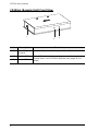
CE250AR (Remote Unit) Front View
# Description Function
1 Grounding
Terminal
The grounding wire (used to ground the unit) attaches here.
2 On Line LED These LEDs indicate the operating status of the Local and
Remote units. See CE250AR (Remote Unit), page 16, for
details.
3 Power LED
3
2
1

Chapter 1. Introduction
7
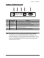
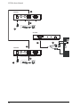
CE250AL / CE250AR Rear View
Note: The Local unit (CE250AL) can get its power from the computer –
external power is only required when the power from the local
computer/computers in the KVM installation is insufficient. If you
choose to purchase a power adapter for use with the CE250
AL, be sure
to get one with the same specifications as the one provided in this
package for the CE250AR.
# Description Function
1 Power Jack The cable from the DC Power Adapter plugs into this jack.*
2 Mouse Port The console mice plug into these ports.
3 Keyboard Port The console keyboards plugs into these ports.
4 Link Port The Cat 5 cable that connects the Remote and Local units
plugs into this connector.
5 Video Port The console monitors plug into these ports.
1
32 4 5

CE250A User Manual
8
This Page Intentionally Left Blank

9
Chapter 2
Hardware Setup
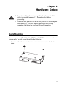
Rack Mounting
For convenience and flexibility, the CE250AL and CE250AR can be mounted on
system racks. To rack mount a unit do the following:
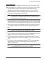
1. Unscrew either the two front screws or two rear screws from the bottom
panel.
1. Important safety information regarding the placement of this
device is provided on page 17. Please review it before
proceeding.
2. Make sure that power to all the devices you will be installing has
been turned off. You must unplug the power cords of any
computers that have the Keyboard Power On function.

CE250A User Manual
10
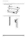
2. Use the screws you just removed to attach the mounting bracket that came
with your package to the unit:
3. Screw the bracket into any convenient location on the rack.
Page is loading ...
Page is loading ...
Page is loading ...
Page is loading ...
Page is loading ...
Page is loading ...
Page is loading ...
Page is loading ...
Page is loading ...
Page is loading ...
Page is loading ...
Page is loading ...
Page is loading ...
-
 1
1
-
 2
2
-
 3
3
-
 4
4
-
 5
5
-
 6
6
-
 7
7
-
 8
8
-
 9
9
-
 10
10
-
 11
11
-
 12
12
-
 13
13
-
 14
14
-
 15
15
-
 16
16
-
 17
17
-
 18
18
-
 19
19
-
 20
20
-
 21
21
-
 22
22
-
 23
23
-
 24
24
-
 25
25
-
 26
26
-
 27
27
-
 28
28
-
 29
29
-
 30
30
-
 31
31
-
 32
32
-
 33
33


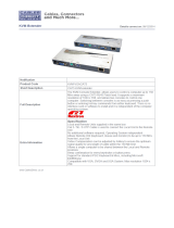
ATEN CE250a is a KVM (Keyboard, Video, Mouse) Extender that allows you to control a computer from up to 164 feet (50 meters) away. This can be useful in a variety of scenarios, such as:
- Placing the computer in a secure or environmentally controlled location, while still being able to access it from a remote location.
- Extending the reach of your KVM signal to a remote monitor or projector.
- Creating a multi-user workstation, where multiple users can share a single computer. The CE250a is a high-performance KVM extender that supports resolutions up to 1920 x 1200 at 60Hz. It also features:
- 2-port USB hub for connecting peripherals such as printers, scanners, and external storage drives.
Ask a question and I''ll find the answer in the document
Finding information in a document is now easier with AI
Related papers
Other documents
-
ATEN Technology CE250a User manual
-
König SEC-UTS11 Datasheet
-
 Cables Direct KVM-VGACAT5 Datasheet
-
iogear GCE250 User manual
-
LevelOne KVM-0222-V1 Datasheet
-
-
ConnectPRO VGAEDIDKITU1 User manual
-
-
-
Lindy 32489 User manual
