Foundry Networks FGS624P User manual
- Category
- Networking
- Type
- User manual
This manual is also suitable for

Foundry FastIron GS
Compact Layer 2 Switch
POE and POE-Upgradeable
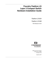
Hardware Installation Guide
FGS624P
FGS624P-POE
FGS648P
FGS648P-POE
FGS624XGP
FGS624XGP-POE
FGS Release 04.0.00
September 2007
™
4980 Great America Parkway
Santa Clara, CA 95054
Tel 408.207.1700
www.foundrynetworks.com

Copyright © 2007 Foundry Networks, Inc. All rights reserved.
No part of this work may be reproduced in any form or by any means – graphic, electronic or mechanical, including
photocopying, recording, taping or storage in an information retrieval system – without prior written permission of the
copyright owner.
The trademarks, logos and service marks ("Marks") displayed herein are the property of Foundry or other third parties.
You are not permitted to use these Marks without the prior written consent of Foundry or such appropriate third party.
Foundry Networks, BigIron, FastIron, IronView, JetCore, NetIron, ServerIron, TurboIron, IronWare, EdgeIron, IronPoint,
the Iron family of marks and the Foundry Logo are trademarks or registered trademarks of Foundry Networks, Inc. in
the United States and other countries.
F-Secure is a trademark of F-Secure Corporation. All other trademarks mentioned in this document are the property of
their respective owners.

September 2007 © 2007 Foundry Networks, Inc. iii
Contents
CHAPTER 1
A
BOUT THIS GUIDE..................................................................................... 1-1
INTRODUCTION ...........................................................................................................................................1-1
W
HAT’S INCLUDED IN THIS EDITION? ...........................................................................................................1-1
A
UDIENCE ..................................................................................................................................................1-1
N
OMENCLATURE .........................................................................................................................................1-1
R
ELATED PUBLICATIONS .............................................................................................................................1-2
H
OW TO GET HELP .....................................................................................................................................1-2
W
EB ACCESS .......................................................................................................................................1-2
E
MAIL ACCESS .....................................................................................................................................1-2
T
ELEPHONE ACCESS ............................................................................................................................1-2
W
ARRANTY COVERAGE ...............................................................................................................................1-2
CHAPTER 2
P
RODUCT OVERVIEW .................................................................................. 2-1
PRODUCT OVERVIEW ..................................................................................................................................2-1
S
OFTWARE FEATURES ................................................................................................................................2-2
H
ARDWARE FEATURES ...............................................................................................................................2-2
FGS624P
AND FGS624P-POE ...........................................................................................................2-2
FGS624XGP
AND FGS624XGP-POE ................................................................................................2-3
FGS648P
AND FGS648P-POE ...........................................................................................................2-3
C
ONTROL FEATURES ............................................................................................................................2-4
F
IBER OPTIC MODULES ......................................................................................................................2-12
P
OWER SUPPLIES ..............................................................................................................................2-12
C
OOLING SYSTEM AND FANS ..............................................................................................................2-13
CHAPTER 3
I
NSTALLING THE FASTIRON GS CHASSIS..................................................... 3-1
UNPACKING A SYSTEM ................................................................................................................................3-1
P
ACKAGE CONTENTS ...........................................................................................................................3-1

FastIron GS Compact Layer 2 Switch Hardware Installation Guide
iv © 2007 Foundry Networks, Inc. September 2007
GENERAL REQUIREMENTS ....................................................................................................................3-1
S
UMMARY OF INSTALLATION TASKS .............................................................................................................3-2
I
NSTALLATION PRECAUTIONS .......................................................................................................................3-3
G
ENERAL PRECAUTIONS .......................................................................................................................3-3
L
IFTING PRECAUTIONS .........................................................................................................................3-3
P
OWER SUPPLY PRECAUTIONS .............................................................................................................3-4
P
REPARING THE INSTALLATION SITE ............................................................................................................3-5
C
ABLING INFRASTRUCTURE ..................................................................................................................3-5
I
NSTALLATION LOCATION ......................................................................................................................3-5
I
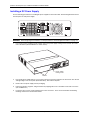
NSTALLING AN ADDITIONAL POWER SUPPLY ................................................................................................3-5
I
NSTALLING AN AC POWER SUPPLY ......................................................................................................3-6
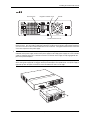
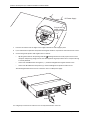
I
NSTALLING A DC POWER SUPPLY ..............................................................................................................3-8
I
NSTALLING THE DEVICE ............................................................................................................................3-11
D
ESKTOP INSTALLATION .....................................................................................................................3-11
R
ACK MOUNT INSTALLATION ...............................................................................................................3-11
W
ALL MOUNT INSTALLATION ...............................................................................................................3-13
P
OWERING ON THE SYSTEM .....................................................................................................................3-14
P
OWERING OFF THE SYSTEM .............................................................................................................3-15
V
ERIFYING PROPER OPERATION ...............................................................................................................3-15
O
BSERVING THE POWER STATUS LEDS ..............................................................................................3-16
A
TTACHING A PC OR TERMINAL ................................................................................................................3-16
CHAPTER 4
C
ONNECTING NETWORK DEVICES AND
C
HECKING CONNECTIVITY ........................................................................... 4-1
ASSIGNING PERMANENT PASSWORDS .........................................................................................................4-1
R
ECOVERING FROM A LOST PASSWORD ................................................................................................4-2
C
ONFIGURING IP ADDRESSES .....................................................................................................................4-3
D
EVICES RUNNING LAYER 2 SOFTWARE ...............................................................................................4-3
C
ONNECTING NETWORK DEVICES ...............................................................................................................4-4
C
ABLE SPECIFICATIONS ........................................................................................................................4-4
C
ONNECTING TO ETHERNET OR FAST ETHERNET HUBS .........................................................................4-4
C
ONNECTING TO WORKSTATIONS, SERVERS, OR ROUTERS ...................................................................4-5
C
ONNECTING A NETWORK DEVICE TO A FIBER PORT .............................................................................4-5
T
ESTING CONNECTIVITY ..............................................................................................................................4-6
P
INGING AN IP ADDRESS ......................................................................................................................4-6
O
BSERVING LEDS ................................................................................................................................4-7
T
RACING A ROUTE ...............................................................................................................................4-8
T
ROUBLESHOOTING NETWORK CONNECTIONS .............................................................................................4-8
U
SING VIRTUAL CABLE TESTING TO DIAGNOSE A CABLE .......................................................................4-8
CHAPTER 5
M
ANAGING THE FASTIRON GS CHASSIS...................................................... 5-1
MANAGING TEMPERATURE SETTINGS ..........................................................................................................5-1
U
SING THE TEMPERATURE SENSOR ......................................................................................................5-1

Contents
September 2007 © 2007 Foundry Networks, Inc. v
DISPLAYING THE TEMPERATURE ...........................................................................................................5-1
D
ISPLAYING TEMPERATURE MESSAGES ................................................................................................5-2
C
HANGING THE TEMPERATURE WARNING LEVEL ...................................................................................5-2
C
HANGING THE CHASSIS TEMPERATURE POLLING INTERVAL ..................................................................5-3
D
ISPLAYING MANAGEMENT MODULE CPU USAGE .......................................................................................5-3
R
EMOVING MAC ADDRESS ENTRIES ...........................................................................................................5-3
CHAPTER 6
H
ARDWARE SPECIFICATIONS....................................................................... 6-1
CHASSIS SPECIFICATIONS ...........................................................................................................................6-2
P
HYSICAL DIMENSIONS AND WEIGHT ....................................................................................................6-2
E
NVIRONMENTAL CONSIDERATIONS ......................................................................................................6-2
C
OOLING .............................................................................................................................................6-3
R
EGULATORY COMPLIANCE ..................................................................................................................6-3
P
OWER SOURCE INTERRUPTIONS .........................................................................................................6-4
M
EAN TIME BETWEEN FAILURE .............................................................................................................6-4
P
OWER DRAW SPECIFICATIONS ............................................................................................................6-5
P
INOUTS AND SIGNALLING ....................................................................................................................6-6
C
ABLE SPECIFICATIONS ........................................................................................................................6-7
P
OWER CORDS ....................................................................................................................................6-9
W
ARRANTY ..........................................................................................................................................6-9
P
OWER SUPPLY SPECIFICATIONS ................................................................................................................6-9
O
VERVIEW ...........................................................................................................................................6-9
K
EY FEATURES ...................................................................................................................................6-10
P
HYSICAL DIMENSIONS AND WEIGHT ..................................................................................................6-10
E
NVIRONMENTAL CONSIDERATIONS ....................................................................................................6-10
P
OWER SUPPLY CONSUMPTION ..........................................................................................................6-11
I
NPUT CONNECTOR AND PLUG ............................................................................................................6-12
R
EGULATORY COMPLIANCE ................................................................................................................6-13
S
AFETY WARNINGS ............................................................................................................................6-13
E
LECTRICAL SPECIFICATIONS .............................................................................................................6-14
CHAPTER 7
M
AINTAINING THE FASTIRON GS HARDWARE .............................................. 7-1
HARDWARE MAINTENANCE SCHEDULE .........................................................................................................7-1
R
EPLACING A POWER SUPPLY ....................................................................................................................7-1
I
NSTALLATION PRECAUTIONS AND WARNINGS ........................................................................................7-2
D
ETERMINING WHICH POWER SUPPLY FAILED ......................................................................................7-2
AC P
OWER SUPPLIES ..........................................................................................................................7-2
DC P
OWER SUPPLIES ..........................................................................................................................7-5
I
NSTALLING OR REPLACING A 2-PORT 10-GBE MODULE ...............................................................................7-9
R
EMOVING A 2-PORT 10-GBE MODULE .................................................................................................7-9
I
NSTALLING A 2-PORT 10-GBE MODULE ................................................................................................7-9
I
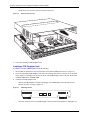
NSTALLING OR REPLACING A POE DAUGHTER CARD ................................................................................7-10
D
ISASSEMBLING THE CHASSIS ............................................................................................................7-11
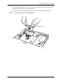
I
NSTALLING A POE DAUGHTER CARD .................................................................................................7-12

FastIron GS Compact Layer 2 Switch Hardware Installation Guide
vi © 2007 Foundry Networks, Inc. September 2007
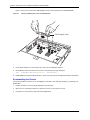
RE-ASSEMBLING THE CHASSIS ............................................................................................................7-14
R
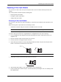
EPLACING A FIBER OPTIC MODULE .........................................................................................................7-15
R
EMOVING A FIBER OPTIC MODULE ....................................................................................................7-15
I
NSTALLING A NEW FIBER OPTIC MODULE ...........................................................................................7-16
C
ABLING A FIBER OPTIC MODULE .......................................................................................................7-16
C
LEANING THE FIBER-OPTIC CONNECTORS ...............................................................................................7-16
D
IGITAL OPTICAL MONITORING ...........................................................................................................7-17
APPENDIX A
REGULATORY STATEMENTS ........................................................................A-1
U.S.A. ...................................................................................................................................................... A-1
I
NDUSTRY CANADA STATEMENT ................................................................................................................. A-1
E
UROPE AND AUSTRALIA ........................................................................................................................... A-1
J
APAN ....................................................................................................................................................... A-1
APPENDIX B
C
AUTIONS AND WARNINGS..........................................................................B-1
CAUTIONS ................................................................................................................................................. B-1
W
ARNINGS ................................................................................................................................................ B-6

September 2007 © 2007 Foundry Networks, Inc. 1 - 1
Chapter 1
About This Guide
Introduction
This guide describes the following FastIron GS® (FGS) Compact Layer 2 POE (Power over Ethernet) and POE-
upgradeable switches from Foundry Networks:
• FGS624P-POE – 24-port POE
• FGS624P – 24-port POE-upgradeable
• FGS624XGP – 24-port POE-upgradeable with 1-port 10-GbE (new in release 02.5.00)
• FGS624XGP-POE – 24-port POE with 1-port 10-GbE (new in release 02.5.00)
• FGS648P-POE – 48-port POE
• FGS648P – 48-port POE-upgradeable
This guide includes procedures for installing the hardware and configuring essential, basic parameters such as
permanent passwords and IP addresses. The basic software configuration procedures show how to perform
tasks using the CLI. This guide also includes instructions for managing and maintaining the hardware.
What’s Included in This Edition?
This edition includes the following FastIron GS releases:
• 02.5.00
• 02.4.00
• 03.0.00
Audience
This guide is designed for network installers, system administrators, and resellers who will install the FGS
hardware. This guide assumes a working knowledge of Layer 2 switching.
Nomenclature
This guide uses the following typographical conventions to show information:
Italic highlights the title of another publication and occasionally emphasizes a word or phrase.
Bold highlights a CLI command.
Bold Italic highlights a term that is being defined.

FastIron GS Compact Layer 2 Switch Hardware Installation Guide
1 - 2 © 2007 Foundry Networks, Inc. September 2007
NOTE: A note emphasizes an important fact or calls your attention to a dependency.
CAUTION: A caution calls your attention to a possible hazard that can damage equipment.
WARNING: A warning calls your attention to a possible hazard that can cause injury or death.
Related Publications
The following Foundry Networks documents supplement the information in this guide.
• Foundry FastIron Configuration Guide – for FastIron Edge Switch X Series (FESX), FastIron SuperX Switch
(FSX), FastIron SX 800, FastIron SX 1600, FastIron Workgroup Switch X Series (FWSX), and FastIron GS
(FGS), provides configuration procedures for system-level features, Layer 2 features, and configuration
information for Layer 3 enterprise routing protocols including IP, RIP, IP multicast, OSPF, BGP4, VRRP and
VRRPE. This guide also provides procedures for securing management access to Foundry devices and for
protecting against Denial of Service (DoS) attacks.
• Foundry Management Information Base Reference – contains the Simple Network Management Protocol
(SNMP) Management Information Base (MIB) objects supported on Foundry devices.
• Release Notes for the FastIron GS Switch (FGS) – describes features introduced in each software release,
lists features that are supported on the FGS, and describes how configuration procedures or defaults differ
from those on other Foundry devices, due to the FGS’s hardware architecture.
To order additional copies of these manuals, do one of the following:
• Call 1.877.TURBOCALL (887.2622) in the United States or 1.408.207.1600 outside the United States.
• Send email to info@foundrynet.com.
NOTE: For the latest edition of this document, which contains the most up-to-date information, see
kp.foundrynet.com.
How to Get Help
Foundry Networks technical support will ensure that the fast and easy access that you have come to expect from
your Foundry Networks products will be maintained.
Web Access
• kp.foundrynet.com
Email Access
Technical requests can also be sent to the following email address:
• support@foundrynet.com
Telephone Access
• 1.877.TURBOCALL (887.2622) United States
• 1.408.207-1600 Outside the United States
Warranty Coverage
Contact Foundry Networks using any of the methods listed above for information about the standard and extended
warranties.

September 2007 © 2007 Foundry Networks, Inc. 2 - 1
Chapter 2
Product Overview
This chapter contains the following information:
• “Product Overview” on page 2-1
• “Software Features” on page 2-2
• “Hardware Features” on page 2-2
Product Overview
This chapter contains an overview of the following Foundry Networks FastIron GS® (FGS) products:
• FGS624P-POE – 24-port POE
• FGS624P – 24-port POE-upgradeable
• FGS624XGP – 24-port POE-upgradeable with 1-port 10-GbE (new in release 02.5.00)
• FGS624XGP-POE – 24-port POE with 1-port 10-GbE (new in release 02.5.00)
• FGS648P-POE – 48-port POE
• FGS648P – 48-port POE-upgradeable
The FGS provides high port density within a compact form factor. All devices provide 128 MB of SDRAM when
shipped from the factory.
You can order the FGS
with or without Power over Ethernet (POE) installed. If you order a POE-upgradeable
device, you can later upgrade your device to a POE device.
The FGS delivers a full complement of standards-based, feature-rich Layer 2 switching and Base Layer 3
capability. The extensive feature set supports network requirements ranging from basic connectivity to multicast-
enabled full streaming audio and video applications for converged services such as Voice over IP (VoIP).
The FGS, together with Foundry’s FastIron X Series devices, provide an integral range of network connectivity
within the entire enterprise network. The FGS provides high port density and Gigabit Ethernet (GbE) uplinks in a
compact form factor. All models optionally support two 10-GbE uplink ports. The FGS624XGP and FGS624XGP-
POE, introduced in release 02.5.00, come with one 10-GbE uplink port.
The POE devices provide electrical power over existing Ethernet cables, supporting the need for integrated data,
voice, and video applications.

FastIron GS Compact Layer 2 Switch Hardware Installation Guide
2 - 2 © 2007 Foundry Networks, Inc. September 2007
Software Features
Software features differ depending on the software version that is loaded on the device. When first shipped, the
FGS devices support full Layer 2 Switching and Base Layer 3 Switching.
For a complete list of software features supported on the FGS, see the release notes or the Foundry FastIron
Configuration Guide.
Hardware Features
This section describes the physical characteristics of Foundry’s FGS models. For details about physical
dimensions, power supply specifications, and pinouts, see the chapter “Hardware Specifications” on page 6-1.
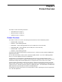
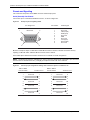
FGS624P and FGS624P-POE
The FGS624P is POE-upgradeable. You can upgrade it by installing a POE daughter card.
The FGS624P-POE already has the POE daughter card installed.
Figure 2.1 shows the FGS624P and FGS624P-POE.
Figure 2.1 FGS624P and RGS624P-POE
The FGS624P and FGS624P-POE have the following ports:
• 24 10/100/1000 Mbps Copper ports that support 100Base-TX and 1000Base-T RJ-45 connectors
• Four Gigabit Fiber ports for mini-GBIC optical transceivers (also called Small Form Factor Pluggable (SFP)
MultiSource Agreement (MSA)-compliant optical transceivers)
Note that ports 1 – 4 of the copper ports and 1F – 4F of the fiber ports are combination ports, meaning either
the copper port or its corresponding fiber port can be active at a time. For example, for copper port 1 and
fiber port 1F, only one of these ports can be active at any given time. The same applies to copper port 2 and
fiber port 2F, and so forth. You can use a combination of fiber and copper ports or all four copper or all four
fiber ports, as needed. For more information, see “Combination Ports” on page 2-7.
• Optionally, two 10-GbE ports. See “10 Gbps Ports” on page 2-7.
26
25
FGS-2XG

Product Overview
September 2007 © 2007 Foundry Networks, Inc. 2 - 3
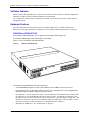
FGS624XGP and FGS624XGP-POE
The FGS624XGP is POE-upgradeable. You can upgrade it by installing a POE daughter card.
The FGS624XGP-POE already has the POE daughter cards installed.
Figure 2.2 shows the FGS624XGP and FGS624XGP-POE.
Figure 2.2 FGS624XGP and FGS624XGP-POE
The FGS624XGP and FGS624XGP-POE have the following ports:
• 24 10/100/1000 Copper ports that support 100Base-TX and 1000Base-T RJ-45 connectors
• Four Gigabit Fiber uplink ports (1F – 4F) for mini-GBIC optical transceivers (also called Small Form Factor
Pluggable (SFP) Multisource Agreement (MSA)-compliant optical transceivers)
Note that ports 1 – 4 of the copper ports and 1F – 4F of the fiber ports are combination ports, meaning either
the copper port or its corresponding fiber port can be active at a time. For example, for copper port 1 and
fiber port 1F, only one of these ports can be active at any given time. The same applies to copper port 2 and
fiber port 2F, and so forth. You can use a combination of fiber and copper ports or all four copper or all four
fiber ports, as needed. For more information, see “Combination Ports” on page 2-7.
• One built-in 10-GbE port. See “10 Gbps Ports” on page 2-7.
• Optionally, two additional 10-GbE ports. See “10 Gbps Ports” on page 2-7.
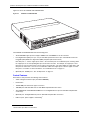
FGS648P and FGS648P-POE
The FGS648P is POE-upgradeable. You can upgrade it to a POE device by installing one or two POE daughter
cards. A single POE daughter card supports 24 POE ports. Two POE daughter cards support 48 POE ports.
The FGS648P-POE already has the POE daughter cards installed.
Slot
3
Slot 1

FastIron GS Compact Layer 2 Switch Hardware Installation Guide
2 - 4 © 2007 Foundry Networks, Inc. September 2007
Figure 2.3 shows the FGS648P and FGS648P-POE
.
Figure 2.3 FGS648P and FGS648P-POE
The FGS648P and FGS648P-POE have the following ports:
• 48 10/100/1000 Copper ports that support 100Base-TX and 1000Base-T RJ-45 connectors
• Four Gigabit Fiber uplink ports (1F – 4F) for mini-GBIC optical transceivers (also called Small Form Factor
Pluggable (SFP) Multisource Agreement (MSA)-compliant optical transceivers)
Note that ports 1 – 4 of the copper ports and 1F – 4F of the fiber ports are combination ports, meaning either
the copper port or its corresponding fiber port can be active at a time. For example, for copper port 1 and
fiber port 1F, only one of these ports can be active at any given time. The same applies to copper port 2 and
fiber port 2F, and so forth. You can use a combination of fiber and copper ports or all four copper or all four
fiber ports, as needed. For more information, see “Combination Ports” on page 2-7.
• Optionally, two 10-GbE ports. See “10 Gbps Ports” on page 2-7.
Control Features
Each device’s front panel has the following control features:
• Serial management interface (the port labeled Console)
• Reset button
• 10/100/1000 ports with RJ-45 copper connectors
• 100/1000 ports with mini-GBIC slots for SFP MSA-compliant fiber transceivers
• The FGS624XGP and FGS624XGP-POE have one 10-Gigabit Ethernet port for XFP MSA compliant fiber
connector(s)
• Optionally, two 10 Gigabit Ethernet ports for XFP MSA-compliant fiber connectors
• LEDs for ports, power supplies, and stacking
1
1.Reserved for possible use in the future.
FGS-2XG

Product Overview
September 2007 © 2007 Foundry Networks, Inc. 2 - 5
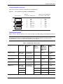
Figure 2.4 shows the front panel of the FGS624P and FGS624P-POE.
Figure 2.4 FGS624P and FGS624P-POE Front Panel
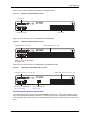
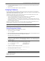
Figure 2.5 shows the front panel of the FGS648P and FGS648P-POE.
Figure 2.5 FGS648P and FGS648P-POE Front Panel
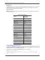
Figure 2.6 shows the front panel of the FGS624XGP and FGS624XGP-POE.
Figure 2.6 FGS624XGP and FGS624XGP-POE Front Panel
Serial Management Interface (Console Port)
The serial management interface (the port labelled Console) enables you to configure and manage the device
using a third-party terminal emulation application on a directly connected PC. A straight-through EIA/TIA DB-9
serial cable (M/F) ships with the device. The serial management interface is located in the left corner of the front
panel.
1F 2F 3F4F
Console
Lnk
Act
PS1PS2Pwr
5678
1
1
2
2 3
Stack
4
3
4
5
6
7
8
9
10
11
12
13
14
15
16
17
18
19
20
21
22
23
24
Odd
Even
PoE
Lnk-Act
25 26
Lnk
FGS-2XG
Act
Ports 1-4
Ports 25 and 26 Ports 1-24
49
1F 2F 3F 4F
Console
50
Lnk
Act
PS1 PS2 Pwr
5678
1
1
2
23
Stack
4
3
4
5
6
7
8
9
10
11
12
13
14
15
16
17
18
19
20
21
22
23
24
25
26
27
28
29
30
31
32
33
34
35
36
37
38
39
40
41
42
43
44
45
46
47
48
Odd
Even
PoE
Lnk-Act
Lnk
Act
GbE Fiber Ports (1F - 4F)
Optional 2-port 10-GbE Module
(port 49 and 50)
GbE Copper Ports (1 - 48)
1F 2F 3F4F
Console
Lnk
Act
PS1PS2 Pwr
5678
1
1
2
2 3
Stack
4
3
4
5
6
7
8
9
10
11
12
13
14
15
16
17
18
19
20
21
22
23
24
Odd
Even
PoE
Lnk-Act
Lnk
FGS-2XG
Act
Lnk
Act
GbE Fiber Ports (slot 1, ports 1F - 4F) GbE Copper Ports (slot 1, ports 1 - 24)
Optional 2-port 10-GbE Module
(slot 2, ports 1 and 2)
1-port 10-GbE Module
(slot 3, port 1)
Slot 2
12
Slot 3
Slot 1

FastIron GS Compact Layer 2 Switch Hardware Installation Guide
2 - 6 © 2007 Foundry Networks, Inc. September 2007
Reset Button
The reset button allows you to restart the system without switching the power supplies off and on or using the CLI
or Web management interface. The button is located to the right of the serial management interface and is
recessed to prevent it from being pushed accidentally.
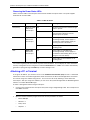
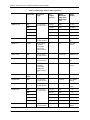
Network Interfaces
Table 2.1 describes the network interfaces supported on the FGS devices. For network interface specifications,
see Table 6.7 on page 6-7.
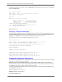
Viewing the Media Types Installed in the Ports
The output of the show media command displays the type of media (copper or fiber) installed in the ports. The
output differs between devices running software release 02.4.00 and release 02.5.00 or later. Starting in software
release 02.5.00, the software uses a stacking nomenclature.
The following shows an example of the show media output in pre-release 02.5.00.
FastIron(config)# show media
1:M-GBXD 2:M-LHB 3:M-FBX 4:M-SX2 5: C 6: C 7: C 8: C 9: C 10: C 11: C 12: C 13:
C 14: C 15: C 16: C 17: C 18: C 19: C 20: C 21: C 22: C 23: C 24: C 25:XG-ZR
1550.0 nm 26:XG-SR 27:
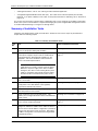
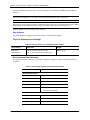
Table 2.1: Network Interfaces
Interface Show Media
Description
1000Base-BX-D M-GBXD
1000Base-BX-U M-GBXU
1000Base-LHA M-LHA
1000Base-LHB M-LHB
1000Base-LX M-LX
1000Base-SX M-SX
1000Base-SX2 M-SX2
1000Base-T C
100Base-BX M-FBX
100Base-FX M-FX
10GBase-ER XG-ER
10GBase-LR XG-LR
10GBase-SR XG-SR
10GBase-ZR XG-ZR
10GBase-ZRD XG-ZRD
CX4 10GbE module CX4
10GbE XFP and CX4 module CX4
1310-MMF 10GbE 1310-NM

Product Overview
September 2007 © 2007 Foundry Networks, Inc. 2 - 7
The following shows an example of the show media output in release 02.5.00 and later.
FastIron(config)# show media
0/1/1:M-SX 0/1/2: C 0/1/3: C 0/1/4: C 0/1/5: C 0/1/6: C 0/1/7: C 0/1/8: C 0/1/9:
C 0/1/10: C 0/1/11: C 0/1/12: C 0/1/13: C 0/1/14: C 0/1/15: C 0/1/16: C 0/1/17:
C 0/1/18: C 0/1/19: C 0/1/20: C 0/1/21: C 0/1/22: C 0/1/23: C 0/1/24: C
0/2/1:XG-LMR 0/2/2:1310-NM
The “Show Media Description” column in Table 2.1 shows the text that displays in the output of the show media
command for each connector type.
10/100/1000 Mbps Ports
The 10/100/1000 copper ports use auto-sensing and auto-negotiating to determine the speed (10 Mbps, 100
Mbps, or 1000 Mbps) and mode (full-duplex or half-duplex) of the port at the other end of the link and adjust port
speed accordingly.
10/100/1000 ports on the FGS devices support RJ-45 copper connectors. The output of the show media
command displays C next to the ports that have copper connectors installed.
Gigabit copper ports on the FGS models support auto MDI/MDIX detection. For more information about this
feature, see "Configuring MDI/MDIX" in the Foundry FastIron Configuration Guide.
100/1000 Mbps Ports
The 100/1000 fiber ports (ports 1F – 4F) on the FGS devices support the SFP fiber connectors listed in Table 2.1.
Combination Ports
Ports 1 – 4 of the copper ports and 1F – 4F of the fiber ports are combination ports, meaning either the copper
port or its corresponding fiber port can be active at a time. For example, for copper port 1 and fiber port 1F, only
one of these ports can be active at any given time. The same applies to copper port 2 and fiber port 2F, and so
forth. You can use a combination of fiber and copper ports or all four copper or all four fiber ports, as needed.
If you attach both the copper and fiber connectors for a port to the network, the fiber connectors take precedence
over the copper connectors. These ports support true media automatic detection, meaning the device will select
the fiber or copper connector based on link availability. If a fiber link cannot be established, the device will select
the copper media.
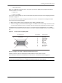
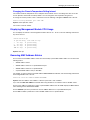
10 Gbps Ports
This section describes the 10-GbE modules
1-Port 10-GbE Module
The 1-port 10-GbE module is installed in the FGS624XGP and FGS624XGP-POE (shown in Figure 2.4). This
module is factory-installed only. It is not a field-upgradeable module. This module is a 10-GbE fiber uplink for 10-
Gigabit Small Form Factor Pluggable (XFP) MSA-compliant optical transceiver.
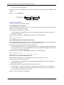
Figure 2.7 shows the 1-port 10-GbE module. This port supports the 10-GbE connector types (10GBase) listed in
Table 2.1.
Figure 2.7 1-port 10-GbE Module
2-port 10-GbE Module
The 2-port 10-GbE module on the FGS is optional. You can order the FGS with one of these 2-port 10-Gigabit
module installed at the factory, or you can later upgrade your device.
The following 2-port 10-Gigabit Ethernet module is supported:
• 2-port 10-GbE fiber uplinks for 10-Gigabit Small Form Factor Pluggable (XFP) MSA-compliant optical
1 XFP port

FastIron GS Compact Layer 2 Switch Hardware Installation Guide
2 - 8 © 2007 Foundry Networks, Inc. September 2007
transceivers (part number FGS-2XG).
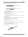
Figure 2.8 shows the 2-port 10-GbE module. These ports support the 10-GbE connector types (10GBase) listed
in Table 2.1.
Figure 2.8 2-port 10-GbE Module
10 Gbps CX4 and XFP Ports
This section describes the 10-GbE CX4 modules.
2-port CX4 Module (Release 02.6.00)
The 2-port CX4 module on the FGS is optional. You can order the FGS with a 2-port CX4 module installed at the
factory, or you can later upgrade your device.
The following 2-port CX4 module is supported:
• 2-port CX4 uplinks for 10-Gigabit Small Form Factor Pluggable (XFP) MSA-compliant optical transceivers
(part number FGS-2XGC).
When this module is installed, the show media command returns the following display:
FGS648 Switch#sh media
0/2/1:CX4 0/2/2:CX4
2-port 10-GbE Hybrid Interface Module (Release 02.6.00)
The 2-port 10-GbE hybrid interface module contains a CX4 port and an XFP port. You can order the FGS with one
a 2-port hybrid module installed at the factory, or you can later upgrade your device.
The following 2-port 10-GbE hybrid interface module is supported:
• 2-port 10-GbE hybrid uplinks; one for a 10-Gigabit Small Form Factor Pluggable (XFP) MSA-compliant optical
transceiver and one for a 2-port CX4 10-Gigabit Small Form Factor Pluggable (XFP) MSA-compliant optical
transceiver (part number FGS-1XG1XGC).
When this module is installed, the show media command returns the following display:
FGS648 Switch#sh media
0/2/1:<depends on transceiver installed> 0/2/2:CX4
10GbE XFP Transceiver (FGS624XGP Models Only)
Release 02.6.00 introduced support for a 10GbE XFP transceiver specifically in port 1, slot 3..
The following 2-port CX4 module is supported:
• 2-port CX4 uplinks for 10-Gigabit Small Form Factor Pluggable (XFP) MSA-compliant optical transceivers
(part number FGS-2XGC).
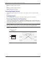
Link and Activity LEDs on the module faceplates indicate operational status:
• If the Lnk LED is on, the port is connected. If the Lnk LED is off, no connection exists, or the link is down.
• If the Act LED is on or blinking, traffic is being transmitted and received on the port. If the Act LED is off, no
traffic is being transmitted or received on the port.
Figure 2.9 shows the faceplates of both modules:
2 XFP ports

Product Overview
September 2007 © 2007 Foundry Networks, Inc. 2 - 9
Figure 2.9 2-port CX4 10GbE Module and 10GbE and CX4 Module
Cable Specifications for New Optics Modules
The following cable specifications apply to the CX4 ports, which are included in the new 10GbE interface modules
(FGS-2XGC and FGS-1XG1XGC):
• Support for 802.3ak or 10 Gigabit Ethernet CX4 standard
• Support of up to 15m in length
• Requires latch-style receptacle or SFF-8470 plug
• Recommended CX4 cable: Manufactured by WL Gore, part number IBN6600-15, CX4 Assembly - 26AWG
SPC 15.0m
CX4 10Gbps XFP Transceiver
This release introduces a twin-axial 10G copper CX4 XFP transceiver that can be installed in any 10G port. For a
link to operate properly, both sides must use identical CX4 transceivers.
The show media command identifies the CX4 as XG-CX4 as shown here:
FGS624P Switch#sh media
0/1/1: C 0/1/2:M-SX 0/1/3: C 0/1/4: C 0/1/5: C 0/1/6: C 0/1/7: C 0/1/8: C 0/1/9:
C 0/1/10: C 0/1/11: C 0/1/12: C 0/1/13: C 0/1/14: C 0/1/15: C 0/1/16: C 0/1/17:
C 0/1/18: C 0/1/19: C 0/1/20: C 0/1/21: C 0/1/22: C 0/1/23: C 0/1/24: C
0/2/1:XG-SR 0/2/2:XG-SR 0/3/1:XG-CX4
The CX4 transceiver requires a 15 meter CX4-grade cable, which may be purchased from Foundry Networks.
Refer to part number CAB-CX4-0050 when ordering.
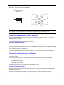
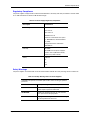
Figure 2.10 shows the CX4 transceiver. Figure 2.11 shows the CX4-grade cable.
Figure 2.10 CX4 Transceiver
10GbE 2-port CX4 Module
10GbE XG and CX4 Module
Lnk
Act
Lnk
Act
Lnk
Act
Lnk
Act

FastIron GS Compact Layer 2 Switch Hardware Installation Guide
2 - 10 © 2007 Foundry Networks, Inc. September 2007
Figure 2.11 CX4 Transceiver Cable
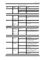
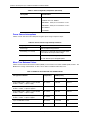
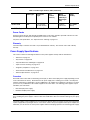
LEDs for Network Interfaces and Power Supplies
The fiber and copper ports on the FGS provide status information using the LEDs listed in Table 2.2.
• The 10/100/1000 copper ports (1 – 24 or 1 – 48) use the LEDs located on the top left and top right of the
upper copper connectors. The LEDs are combined Link/Activity (Lnk/Act) LEDs. The LED on the left side is
for the upper copper connector. The LED on the right side is for the lower copper connector.
• The 100/1000 fiber ports (1F – 4F) use the LEDs located beneath the fiber connectors. The LEDs are
combined Link/Activity (Lnk/Act) LEDs.
• The POE ports (1 – 24) use the round LEDs located beneath the copper ports. The first (left-most) LED is for
port 1, the second LED is for port 2, the third LED is for port 3, and so forth.
• The 10 Gbps fiber ports use the LEDs located beside them.
• The FastIron GS with stacking
1
use the Stack LEDs (1 – 8) located to the right of the console port.
• The power supplies use the Pwr, PS1, and PS2 LEDs on the left side of the front panel, beneath the console
port.
1.Reserved for possible use in the future.
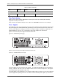
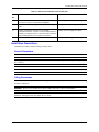
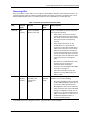
Table 2.2: LEDs
LED Position State Meaning
10/100/1000 Copper Port LEDs
Lnk/Act Located along
the top of the
copper ports
Left for upper
copper
connector
Right for lower
copper
connector
On The link is up.
Off The link is down.
Blinking The port is transmitting and/or receiving
traffic
100/1000 Fiber Port LEDs
CX4 Transceiver Infiniband cable

Product Overview
September 2007 © 2007 Foundry Networks, Inc. 2 - 11
Lnk/Act Bottom left On The link is up.
Off The link is down.
Blinking The port is transmitting and/or receiving
traffic.
10 Gbps Port LEDs
Lnk Located beside
the 10-GbE
port.
This is the top-
most LED.
On The port is connected.
Off No fiber port connection exists or the link
is down.
Act Located beside
the 10-GbE
port.
This is the
bottom-most
LED.
On or Blinking Traffic is being transmitted and/or received
on the fiber port.
Off No traffic is being transmitted or received
on the fiber port.
POE Port LEDs
POE Located along
the bottom of
the copper ports
Left for upper
port
Right for lower
port
On (Green) The port is enabled, a power-consuming
device has been detected, and the
module is supplying power to the device.
Off The port is not providing in-line power.
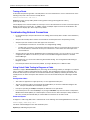
Power Supply LEDs
Power Right-most LED
beneath the
console port
On The device is powered on and has enough
power to operate.
Off The device is not powered on, or has
been powered on but does not have
sufficient power to operate.
PS1 Left-most LED
beneath the
console port
On Power supply 1 is installed and is
functioning normally. Power supply 1 is
located in the right-hand bay (when you
are facing the rear of the device).
Off Power supply 1 is not installed or is not
providing power.
PS2 Middle LED
beneath the
console port
On Power supply 2 is installed and is
functioning normally. Power supply 2 is
located in the left-hand bay (when you are
facing the rear of the device).
Off Power supply 2 is not installed or is not
providing power.
Table 2.2: LEDs (Continued)
LED Position State Meaning

FastIron GS Compact Layer 2 Switch Hardware Installation Guide
2 - 12 © 2007 Foundry Networks, Inc. September 2007
Fiber Optic Modules
Table 6.7 in the chapter “Hardware Specifications” lists the types of fiber optic modules (SFPs and XFPs)
supported on Foundry’s FGS devices.
Table 2.1 lists the description that displays in the output of the show media command for each media type.
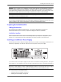
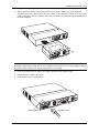
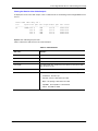
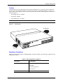
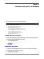
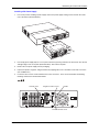
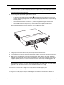
Power Supplies
Each FGS device comes with one alternating-current (AC) power supply (part number RPS-FGS) or direct-current
(DC) power supply (part number RPSDC-FGS), depending on how it was ordered from the factory. All models
have two power supply slots, enabling you to install a second power supply for redundancy (if applicable) or for
additional POE power. You can use any combination of AC and DC supplies in the same device.
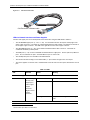
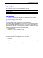
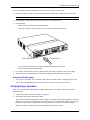
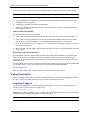
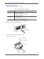
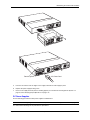
Figure 2.12 shows the AC power supply used with the FastIron GS.
Figure 2.12 RPS-FGS AC power supply
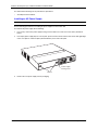
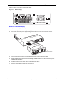
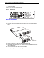
Figure 2.13 shows the DC power supply used with the FastIron GS.
Figure 2.13 RPSDC-FGS DC power supply
The power supplies are auto-sensing and auto-switching. The supplies provide 600 watts of total output power,
including +12VDC @ 10A to the system and -48VDC@ 10A for Power over Ethernet applications. The supplies
provide 100-240 VAC input, 50-60Hz @ 8A to 3.2A.
The power supplies can be swapped in or out of the device while the device is running. You can remove and insert
a power supply without opening the chassis. If the device contains redundant power supplies, you can remove
Stacking LEDs
Reserved for future
use
Table 2.2: LEDs (Continued)
LED Position State Meaning
Page is loading ...
Page is loading ...
Page is loading ...
Page is loading ...
Page is loading ...
Page is loading ...
Page is loading ...
Page is loading ...
Page is loading ...
Page is loading ...
Page is loading ...
Page is loading ...
Page is loading ...
Page is loading ...
Page is loading ...
Page is loading ...
Page is loading ...
Page is loading ...
Page is loading ...
Page is loading ...
Page is loading ...
Page is loading ...
Page is loading ...
Page is loading ...
Page is loading ...
Page is loading ...
Page is loading ...
Page is loading ...
Page is loading ...
Page is loading ...
Page is loading ...
Page is loading ...
Page is loading ...
Page is loading ...
Page is loading ...
Page is loading ...
Page is loading ...
Page is loading ...
Page is loading ...
Page is loading ...
Page is loading ...
Page is loading ...
Page is loading ...
Page is loading ...
Page is loading ...
Page is loading ...
Page is loading ...
Page is loading ...
Page is loading ...
Page is loading ...
Page is loading ...
Page is loading ...
Page is loading ...
Page is loading ...
Page is loading ...
Page is loading ...
Page is loading ...
Page is loading ...
Page is loading ...
Page is loading ...
Page is loading ...
Page is loading ...
Page is loading ...
Page is loading ...
Page is loading ...
Page is loading ...
Page is loading ...
Page is loading ...
Page is loading ...
Page is loading ...
Page is loading ...
Page is loading ...
Page is loading ...
Page is loading ...
Page is loading ...
Page is loading ...
-
 1
1
-
 2
2
-
 3
3
-
 4
4
-
 5
5
-
 6
6
-
 7
7
-
 8
8
-
 9
9
-
 10
10
-
 11
11
-
 12
12
-
 13
13
-
 14
14
-
 15
15
-
 16
16
-
 17
17
-
 18
18
-
 19
19
-
 20
20
-
 21
21
-
 22
22
-
 23
23
-
 24
24
-
 25
25
-
 26
26
-
 27
27
-
 28
28
-
 29
29
-
 30
30
-
 31
31
-
 32
32
-
 33
33
-
 34
34
-
 35
35
-
 36
36
-
 37
37
-
 38
38
-
 39
39
-
 40
40
-
 41
41
-
 42
42
-
 43
43
-
 44
44
-
 45
45
-
 46
46
-
 47
47
-
 48
48
-
 49
49
-
 50
50
-
 51
51
-
 52
52
-
 53
53
-
 54
54
-
 55
55
-
 56
56
-
 57
57
-
 58
58
-
 59
59
-
 60
60
-
 61
61
-
 62
62
-
 63
63
-
 64
64
-
 65
65
-
 66
66
-
 67
67
-
 68
68
-
 69
69
-
 70
70
-
 71
71
-
 72
72
-
 73
73
-
 74
74
-
 75
75
-
 76
76
-
 77
77
-
 78
78
-
 79
79
-
 80
80
-
 81
81
-
 82
82
-
 83
83
-
 84
84
-
 85
85
-
 86
86
-
 87
87
-
 88
88
-
 89
89
-
 90
90
-
 91
91
-
 92
92
-
 93
93
-
 94
94
-
 95
95
-
 96
96


Foundry Networks FGS624P User manual
- Category
- Networking
- Type
- User manual
- This manual is also suitable for
Ask a question and I''ll find the answer in the document
Finding information in a document is now easier with AI
Related papers
-
 Foundry Networks EdgeIron 4802CF User manual
-
 Foundry Networks LS 648 User manual
-
 Foundry Networks M2404C User manual
-
Foundry Networks FWSX448 Installation guide
-
 Foundry Networks Octal T1-10/100 RIOP User manual
-
 Foundry Networks 250 User manual
-
 Foundry Networks 2402CF User manual
-
 Foundry Networks AR1202E User manual


Other documents
-
VIA Technologies VNT5103Q28PS Installation guide
-
Dahua PFS3010-8GT-65 Quick start guide
-
-
Repotec RP-G2804IXS Owner's manual
-
Equip 250010 Datasheet
-
-
-
CTS IPS-3106-SE-PB User manual
-
Brocade FastIron FGS624P-POE-STK Datasheet
-