Page is loading ...

Foundry FastIron LS
Layer 2 Compact Switch
Hardware Installation Guide
FastIron LS 624
FastIron LS 648
FGS Release 04.0.00
4980 Great America Parkway
Santa Clara, CA 95054
Tel 408.207.1700
September 2007
™

Copyright © 2007 Foundry Networks, Inc. All rights reserved.
No part of this work may be reproduced in any form or by any means – graphic, electronic or mechanical, including
photocopying, recording, taping or storage in an information retrieval system – without prior written permission of the
copyright owner.
The trademarks, logos and service marks ("Marks") displayed herein are the property of Foundry or other third parties.
You are not permitted to use these Marks without the prior written consent of Foundry or such appropriate third party.
Foundry Networks, BigIron, FastIron, IronView, JetCore, NetIron, ServerIron, TurboIron, IronWare, EdgeIron, IronPoint,
the Iron family of marks and the Foundry Logo are trademarks or registered trademarks of Foundry Networks, Inc. in
the United States and other countries.
F-Secure is a trademark of F-Secure Corporation. All other trademarks mentioned in this document are the property of
their respective owners.

September 2007 © 2007 Foundry Networks, Inc. iii
Contents
CHAPTER 1
A
BOUT THIS GUIDE..................................................................................... 1-1
INTRODUCTION ...........................................................................................................................................1-1
W
HAT’S INCLUDED IN THIS EDITION? ...........................................................................................................1-1
A
UDIENCE ..................................................................................................................................................1-1
N
OMENCLATURE .........................................................................................................................................1-1
R
ELATED PUBLICATIONS .............................................................................................................................1-2
H
OW TO GET HELP .....................................................................................................................................1-2
W
EB ACCESS .......................................................................................................................................1-2
E
MAIL ACCESS .....................................................................................................................................1-2
T
ELEPHONE ACCESS ............................................................................................................................1-2
W
ARRANTY COVERAGE ...............................................................................................................................1-2
CHAPTER 2
P
RODUCT OVERVIEW .................................................................................. 2-1
HARDWARE FEATURES ...............................................................................................................................2-1
FLS624, FLS648 ................................................................................................................................2-1
C
ONTROL FEATURES ............................................................................................................................2-2
F
IBER OPTIC MODULES ........................................................................................................................2-7
P
OWER SUPPLIES ................................................................................................................................2-7
CHAPTER 3
I
NSTALLING A FASTIRON LS SWITCH........................................................... 3-1
UNPACKING A SYSTEM ................................................................................................................................3-1
P
ACKAGE CONTENTS ...........................................................................................................................3-2
G
ENERAL REQUIREMENTS ....................................................................................................................3-2
S
UMMARY OF INSTALLATION TASKS .............................................................................................................3-3
I
NSTALLATION PRECAUTIONS .......................................................................................................................3-4
G
ENERAL PRECAUTIONS .......................................................................................................................3-4
L
IFTING PRECAUTIONS .........................................................................................................................3-4

Foundry FastIron LS Layer 2 Compact Switch Hardware Installation Guide
iv © 2007 Foundry Networks, Inc. September 2007
POWER PRECAUTIONS .........................................................................................................................3-4
P
REPARING THE INSTALLATION SITE ............................................................................................................3-5
C
ABLING INFRASTRUCTURE ..................................................................................................................3-5
I
NSTALLATION LOCATION ......................................................................................................................3-5
I
NSTALLING THE DEVICE .......................................................................................................................3-5
D
ESKTOP INSTALLATION .......................................................................................................................3-6
R
ACK MOUNT INSTALLATION .................................................................................................................3-6
W
ALL MOUNT INSTALLATION .................................................................................................................3-7
I
NSTALLING A REDUNDANT POWER SUPPLY .................................................................................................3-8
A
BOUT THE RPS2-EIF REDUNDANT POWER SUPPLY ............................................................................3-8
I
NSTALLING A FASTIRON LS REDUNDANT POWER SUPPLY .........................................................................3-10
E
QUIPMENT CHECKLIST ......................................................................................................................3-10
M
OUNTING .........................................................................................................................................3-10
C
ONNECTING SWITCHES TO THE RPS ................................................................................................3-12
P
ORTS PIN-OUT (RPS2-EIF) .............................................................................................................3-14
I
NSTALLING AN OPTIONAL MODULE INTO THE SWITCH ................................................................................3-14
I
NSTALLING AN SFP TRANSCEIVER ............................................................................................................3-15
P
OWERING ON THE SYSTEM .....................................................................................................................3-16
V
ERIFYING PROPER OPERATION ...............................................................................................................3-16
A
TTACHING A PC OR TERMINAL ................................................................................................................3-16
W
IRING MAP FOR SERIAL CABLE ........................................................................................................3-17
CHAPTER 4
C
ONNECTING NETWORK DEVICES AND
C
HECKING CONNECTIVITY ........................................................................... 4-1
ASSIGNING PERMANENT PASSWORDS .........................................................................................................4-1
R
ECOVERING FROM A LOST PASSWORD ................................................................................................4-2
C
ONFIGURING IP ADDRESSES .....................................................................................................................4-3
D
EVICES RUNNING LAYER 2 SOFTWARE ...............................................................................................4-3
C
ONNECTING NETWORK DEVICES ...............................................................................................................4-4
C
ONNECTORS ......................................................................................................................................4-4
C
ABLE SPECIFICATIONS ........................................................................................................................4-4
C
ONNECTING TO ETHERNET OR FAST ETHERNET HUBS .........................................................................4-4
C
ONNECTING TO WORKSTATIONS, SERVERS, OR ROUTERS ...................................................................4-5
C
ONNECTING A NETWORK DEVICE TO A FIBER PORT .............................................................................4-5
T
ESTING CONNECTIVITY ..............................................................................................................................4-6
O
BSERVING LEDS ................................................................................................................................4-6
T
ROUBLESHOOTING NETWORK CONNECTIONS .............................................................................................4-7
CHAPTER 5
M
AINTAINING THE FASTIRON LS HARDWARE............................................... 5-1
MANAGING FASTIRON LS TEMPERATURE SETTINGS .....................................................................................5-1
D
ISPLAYING MANAGEMENT MODULE CPU USAGE .......................................................................................5-4
H
ARDWARE MAINTENANCE SCHEDULE .........................................................................................................5-4
I
NSTALLING OR REPLACING A 10-GIGABIT ETHERNET MODULE .....................................................................5-4

Contents
September 2007 © 2007 Foundry Networks, Inc. v
INSTALLING AN OPTIONAL MODULE INTO THE SWITCH ............................................................................5-5
R
EMOVING A 10-GIGABIT ETHERNET MODULE .......................................................................................5-5
R
EPLACING A FIBER OPTIC MODULE ...........................................................................................................5-5
R
EMOVING A FIBER OPTIC MODULE ......................................................................................................5-6
I
NSTALLING A NEW FIBER OPTIC MODULE .............................................................................................5-6
C
ABLING A FIBER OPTIC MODULE .........................................................................................................5-7
C
LEANING THE FIBER-OPTIC CONNECTORS .................................................................................................5-7
D
IGITAL OPTICAL MONITORING .............................................................................................................5-7
CHAPTER 6
T
ROUBLESHOOTING .................................................................................... 6-1
DIAGNOSING SWITCH INDICATORS ........................................................................................................6-1
P
OWER AND COOLING PROBLEMS ........................................................................................................6-2
I
NSTALLATION ......................................................................................................................................6-2
I
N-BAND ACCESS .................................................................................................................................6-2
CHAPTER 7
H
ARDWARE SPECIFICATIONS....................................................................... 7-1
FASTIRON LS SPECIFICATIONS ....................................................................................................................7-2
P
HYSICAL DIMENSIONS .........................................................................................................................7-2
C
OOLING .............................................................................................................................................7-3
R
EGULATORY COMPLIANCE ..................................................................................................................7-5
W
ARRANTY ..........................................................................................................................................7-6
P
INOUTS AND SIGNALING ......................................................................................................................7-6
C
ABLE SPECIFICATIONS ........................................................................................................................7-7
AC P
OWER SUPPLY .............................................................................................................................7-9
P
OWER CORDS ..................................................................................................................................7-10
R
EDUNDANT POWER SUPPLY SPECIFICATIONS ..........................................................................................7-10
O
VERVIEW .........................................................................................................................................7-10
K
EY FEATURES ...................................................................................................................................7-10
P
HYSICAL DIMENSIONS AND WEIGHT ..................................................................................................7-10
I
NPUT CONNECTOR ............................................................................................................................7-11
R
EGULATORY COMPLIANCE ................................................................................................................7-11
E
NVIRONMENTAL CONSIDERATIONS ....................................................................................................7-12
E
LECTRICAL SPECIFICATIONS .............................................................................................................7-13
APPENDIX A
R
EGULATORY STATEMENTS ........................................................................A-1
U.S.A. ...................................................................................................................................................... A-1
I
NDUSTRY CANADA STATEMENT ................................................................................................................. A-1
E
UROPE AND AUSTRALIA ........................................................................................................................... A-1
J
APAN ....................................................................................................................................................... A-1

Foundry FastIron LS Layer 2 Compact Switch Hardware Installation Guide
vi © 2007 Foundry Networks, Inc. September 2007
APPENDIX B
C
AUTIONS AND WARNINGS..........................................................................B-1
CAUTIONS ................................................................................................................................................. B-1
W
ARNINGS ................................................................................................................................................ B-4

September 2007 © 2007 Foundry Networks, Inc. 1 - 1
Chapter 1
About This Guide
Introduction
This guide describes the following product families from Foundry Networks:
• FastIron LS (FLS) Layer 2 Compact Switch
This guide includes procedures for installing the hardware and configuring essential, basic parameters such as
permanent passwords and IP addresses. The basic software configuration procedures show how to perform
tasks using the CLI. This guide also includes instructions for managing and maintaining the hardware.
This guide applies to the following FastIron LS products:
• FastIron LS 624 (FLS624)
• FastIron LS 648 (FLS648)
What’s Included in This Edition?
This edition describes the following software release:
• For the FastIron LS:
• 04.0.00
Audience
This guide is designed for network installers, system administrators, and resellers who will install the FastIron
hardware. This guide assumes a working knowledge of Layer 2 and Layer 3 Switching and routing concepts.
Nomenclature
This guide uses the following typographical conventions to show information:
Italic highlights the title of another publication and occasionally emphasizes a word or phrase.
Bold highlights a CLI command.
Bold Italic highlights a term that is being defined.
NOTE: A note emphasizes an important fact or calls your attention to a dependency.

Foundry FastIron LS Layer 2 Compact Switch Hardware Installation Guide
1 - 2 © 2007 Foundry Networks, Inc. September 2007
CAUTION: A caution calls your attention to a possible hazard that can damage equipment.
WARNING: A warning calls your attention to a possible hazard that can cause injury or death.
Related Publications
The following Foundry Networks documents supplement the information in this guide.
• Foundry FastIron Configuration Guide - provides basic configuration procedures, including configuration
information for enterprise routing protocols.
• Foundry Management Information Base Reference – contains the Simple Network Management Protocol
(SNMP) Management Information Base (MIB) objects supported on Foundry devices.
NOTE: For the latest edition of this document, which contains the most up-to-date information, see
kp.foundrynet.com.
How to Get Help
Foundry Networks technical support will ensure that the fast and easy access that you have come to expect from
your Foundry Networks products will be maintained.
Web Access
• kp.foundrynetworks.com
Email Access
Technical requests can also be sent to the following email address:
• support@foundrynet.com
Telephone Access
• 1.877.TURBOCALL (887.2622) United States
• 1.408.207.1600 Outside the United States
Warranty Coverage
Contact Foundry Networks using any of the methods listed above for information about the standard and extended
warranties.

September 2007 © 2007 Foundry Networks, Inc. 2 - 1
Chapter 2
Product Overview
This chapter contains an overview of the FastIron
®
LS Layer 2 Compact Switch.
This chapter contains the following information:
Hardware Features
The FastIron LS Series includes two models, the FastIron LS 624 with an option for up to three 1-port 10 Gbps
Ethernet modules, and the FastIron LS 648 with an option for up to two 1-port 10 Gbps Ethernet modules. Both
models support an optional external redundant AC power supply that can power up to four units.
The following sections describe the physical characteristics of the FastIron LS models. For more details about
physical dimensions, power supply specifications, and pinouts, see “Hardware Specifications” on page 2-1.
FLS624, FLS648
The FastIron LS provides high 10/100/1000 port density and 10-Gigabit Ethernet uplinks in a compact form factor.
• The FLS624 has 24 10/100/1000 with four 100/1000 SFP slots, and one front-panel slot for an optional 10-
Gigabit uplink module and two rear-panel 10-Gigabit uplink modules and a redundant power socket.
• The FLS648 has 48 10/100/1000 with four Gigabit SFP slots, and two rear-panel 10-Gigabit uplink modules
and a redundant power socket.
Table 2.1: Chapter Contents
Description See Page
Product overview and the benefits each product offers 2-1
Network topologies in which the devices will be commonly
deployed
2-1
Hardware features and how each major hardware
component functions
2-1

Foundry FastIron LS Layer 2 Compact Switch Hardware Installation Guide
2 - 2 © 2007 Foundry Networks, Inc. September 2007
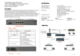
The following figures show the front panels of these FastIron LS models.
Figure 2.1 FastIron LS 624
Figure 2.2 FastIron LS 648
Figure 2.3 FastIron LS 624 and 648 rear panel
Figure 2.4 FastIron LS 624 with module installed
Figure 2.5 FastIron LS 624 and 648 rear panel with modules Installed
Control Features
Each device’s front panel includes the following control features:
• Serial management interface (the port labeled Console)
• Reset button
Serial Management Interface (Console Port)
The serial management interface enables you to configure and manage the device using a third-party terminal
emulation application on a directly connected PC. A straight-through EIA/TIA DB-9 serial cable (M/F) ships with
the device. The serial management interface (the Console port) is located in the right corner of the front panel.
Reset Button
The reset button allows you to restart the system without removing power or using the CLI or Web management
interface. The button is located to the left of the serial management interface and is recessed to prevent it from
being pushed accidentally.
FastIron LS Network Interfaces
The FLS624 and FLS648 provide the following interfaces:
• 10/100/1000 ports with RJ-45 copper connectors
FLS 624
Fastlron LS 624
Fastlron LS 648
45
48
47
46
FLS 648
RPSDCIn12V 13A
100-240V~
50-60Hz 2A
FLS 624
Fastlron LS 624
RPSDCIn12V 13A
100-240V~
50-60Hz 2A

Product Overview
September 2007 © 2007 Foundry Networks, Inc. 2 - 3
• 100/1000 ports with mini-GBIC slots for SFP MSA-compliant fiber transceivers
• Optional 10-Gigabit uplink modules
For information about the type of fiber optic modules supported on the FastIron LS, see “Fiber Optic Modules” on
page 2-7.
FastIron LS 10/100/1000BASE-T Ports
The switches contain 24/48 RJ-45 ports that operate at 10 Mbps or 100 Mbps, half or full duplex, or at 1000 Mbps,
full duplex. Because all ports on these switches support automatic MDI/MDI-X operation, you can use straight-
through cables for all network connections to PCs or servers, or to other switches or hubs. (See “1000BASE-T Pin
Assignments” on page B-3.) In addition, it is ideal and preferred to use MDIX cable for switch-to-switch
connections.
Each of these ports support auto-negotiation, so the optimum transmission mode (half or full duplex), and data
rate (10, 100, or 1000 Mbps) can be selected automatically. If a device connected to one of these ports does not
support auto-negotiation, the communication mode of that port can be configured manually.
Network Interfaces
Table 2.2 describes the network interfaces supported on the FastIron LS. For network interface specifications, see
the table “Cable length summary table” on page 2-7.
Table 2.2: Network Interfaces
Interface Show Media
Description
1000Base-BX-D M-GBXD
1000Base-BX-U M-GBXU
1000Base-LHA M-LHA
1000Base-LHB M-LHB
1000Base-LX M-LX
1000Base-SX M-SX
1000Base-SX2 M-SX2
1000Base-T C
100Base-BX M-FBX
100Base-FX M-FX
10GBase-CX4 XG-ER
10GBase-CX4 (XFP) XG-ER
10GBase-ER XG-ER
10GBase-LR XG-LR
10GBase-LRM XG-LRM
10GBase-SR XG-SR
10GBase-ZR XG-ZR
10GBase-ZRD XG-ZRD

Foundry FastIron LS Layer 2 Compact Switch Hardware Installation Guide
2 - 4 © 2007 Foundry Networks, Inc. September 2007
10 Gigabit Ethernet Module Slots
These switches include two slots on the rear panel for single-port 10GBASE uplink modules with XFP
transceivers, and a single port CX4 module. The 10GBASE transceivers operate at 10 Gbps full duplex with
support for asymmetric flow control (that is, the port honors incoming pause frames, but does not originate pause
frames).
10 Gbps CX4 Ports
This section describes the 10-GbE CX4 module.
10-GbE CX4 Module
The single-port CX4 module is installed in the FLS624 and FLS648 (shown in Figure 2.6). You can order the
FastIron LS with a single-port CX4 module installed at the factory, or you can later upgrade your device. This
module is a 10-GbE-CX4 Ethernet uplink card. It can perform data transmission directly through copper links to
15m(extended 30m) in length.
The following single-port CX4 module is supported:
• single-port CX4 uplinks for 10-Gigabit.
Link and Activity LEDs on the module faceplates indicate operational status:
• If the Lnk LED is on, the port is connected. If the Lnk LED is off, no connection exists, or the link is down.
• If the Act LED is on or blinking, traffic is being transmitted and received on the port. If the Act LED is off, no
traffic is being transmitted or received on the port.
When this module is installed, the show media command returns the following display:
FLS624 Switch(config-if-e1000-0/1/5)#show media
0/1/1: C 0/1/2: C 0/1/3: C 0/1/4: C 0/1/5: C 0/1/6: C 0/1/7: C 0/1/8: C0/1/9:
C 0/1/10: C 0/1/11: C 0/1/12: C 0/1/13: C 0/1/14: C 0/1/15: C 0/1/16: C0/1/17: C 0/
1/18: C 0/1/19: C 0/1/20: C 0/1/21:M-SX 0/1/22: C 0/1/23: C 0/1/24: C0/2/1:CX40/3/
1:XG-LR 0/4/1:1310-NM
Figure 2.6 Single-port 10-GbE-CX4 Module
Cable Specifications for New Module
The following cable specifications apply to the CX4 port, which is included in the new 10GbE interface module
(FLS-1XGC):
• Support for 802.3ak or 10 Gigabit Ethernet CX4 standard
• Support of up to 15m in length
• Requires latch-style receptacle or SFF-8470 plug
• Recommended CX4 cable: Manufactured by WL Gore, part number IBN6600-15, CX4 Assembly - 26AWG
SPC 15.0m
NOTE: The recommended CX4 cable can also be used with a Small Form Factor Pluggable (XFP) MSA-
compliant optical transceiver (part number FGS-2XGC).
Figure 2.7 shows the CX4-grade cable.

Product Overview
September 2007 © 2007 Foundry Networks, Inc. 2 - 5
Figure 2.7 CX4 Transceiver Cable
Port, System and Module Status LEDs
These switches include a display panel for key system and port indications that simplify installation and network
troubleshooting. The LEDs, which are located on the front panel for easy viewing, are shown below and described
in the following tables.
Figure 2.8 Port LEDs
Table 2.3: Port Status LEDs
LED Condition Status
Link/
Activity/Speed
On/Flashing Amber Port has a valid link at 10 or 100 Mbps. Flashing indicates activity.
On/Flashing Green Port has a valid link at 1000 Mbps. Flashing indicates activity.
Off The link is down.
CX4 Transceiver Infiniband cable
Port Status LEDs

Foundry FastIron LS Layer 2 Compact Switch Hardware Installation Guide
2 - 6 © 2007 Foundry Networks, Inc. September 2007
Figure 2.9 System LEDs
Table 2.4: Status LEDs
LED Condition Status
Power Green Internal power is operating normally.
Amber Internal power supply failure.
Off Power off or failure.
Diag Green System self-diagnostic test successfully completed.
Amber System self-diagnostic test has detected a fault.
RPS Green Redundant power supply is providing power.
Amber Primary power supply is active, RPS is on standby.
Off Redundant power supply is off or not plugged in.
Stack Master
1
Green Switch is the Master unit of the stack. State may include topology
discovery, IP assignment, or normal operations.
Flashing Green Switch is the Master unit of the stack, system is initializing.
Amber Switch is operating as a Slave unit in the stack.
Flashing Amber System in Master arbitration/election state.
Off System in standalone mode.
Stack Link
1
Green Uplink and downlink operating normally.
Flashing Green Uplink has failed.
Flashing Amber Downlink has failed.
Off No stacking link present.
Module Green An expansion module is installed and operating normally.
Amber An expansion module is installed but has failed.
Off There is no module installed.
Stack ID
1
1-8 Indicates the switch stack ID.
The Master unit is numbered 1. (Note that If the master unit fails
and a backup unit takes over, the stack IDs do not change.)
Slave units are numbered 2-8.
0 In standalone mode.
FLS 624
Fastlron LS 624
System Status LEDs

Product Overview
September 2007 © 2007 Foundry Networks, Inc. 2 - 7
Figure 2.10 Module LED
Fiber Optic Modules
A list of the types of fiber optic modules supported on Layer 2 Compact Switches can be found in “Cable length
summary table” on page 2-7
NOTE: Some older SFP modules (mini-GBICs for Gigabit Ethernet ports) have latching mechanisms that are
larger than the newer parts. These latches could interfere with one another when inserted side by side into a
SuperX module. Avoid using these mini-GBICs side by side in the same module. These older modules are
identified by the number PL-XPL-00-S13-22 or PL-XPL-00-L13-23 above the serial number. All newer mini-GBICs
do not have this limitation.
Power Supplies
There are two power receptacles on the rear panel of each switch. The standard power receptacle is for the AC
power cord. The receptacle labeled “RPS” is for the optional redundant power supply.
Optional Redundant Power Supply
The switch supports an optional redundant power supply (RPS), that can supply power to the switch in the event
the internal power supply fails.
Power Supply Receptacles
There are two power receptacles on the rear panel of each switch. The standard power receptacle is for the AC
power cord. The receptacle labeled “RPS” is for the optional redundant power supply.
Figure 2.11 Power Supply Receptacles
1. Not currently in use.
Table 2.5: Port Status LEDs
LED Condition Status
Link/Activity On Port has a valid link at 10 Gbps.
On/Flashing Green Flashing indicates activity.
Off The link is down.
Link/Activity LED
Power Socket
Redundant Power Socket
RPSDCIn12V 13A
100-240V~
50-60Hz 2A

Foundry FastIron LS Layer 2 Compact Switch Hardware Installation Guide
2 - 8 © 2007 Foundry Networks, Inc. September 2007

September 2007 © 2007 Foundry Networks, Inc. 3 - 1
Chapter 3
Installing a FastIron LS Switch
WARNING: The procedures in this manual are intended for qualified service personnel.
This chapter describes how to physically install the FastIron LS.
This chapter contains the following topics:
Information about configuring IP addresses and connecting network devices is located in “Connecting Network
Devices and Checking Connectivity”.
Unpacking a System
The Foundry LS systems ship with all of the following items. Please review the list below and verify the contents of
your shipping container. If any items are missing, please contact the place of purchase.
Table 3.1: Chapter Contents
Description See Page
Unpacking the hardware 3-1
Summary of installation tasks 3-3
Installation precautions 3-4
Site preparation 3-5
Installing a redundant power supply 3-8
Mounting the device 3-5
Installing an Optional Module 3-14
Powering ON the device 3-16
Verifying proper operation 3-16
Attaching a PC or terminal to the Foundry device 3-16

Foundry FastIron LS Layer 2 Compact Switch Hardware Installation Guide
3 - 2 © 2007 Foundry Networks, Inc. September 2007
Package Contents
• Foundry Networks FastIron LS
• 115V AC power cable (for AC sourced devices)
• Rack mount brackets
• CD-ROM containing software images and the user documentation (including this guide)
• Warranty card
General Requirements
To manage the system, you need the following items for serial connection to the switch or router:
• A management station, such as a PC running a terminal emulation application.
• A straight-through EIA/TIA DB-9 serial cable (F/F). The serial cable can be ordered separately from Foundry
Networks. If you prefer to build your own cable, see the pinout information in “Attaching a PC or Terminal” on
page 3-16.
You use the serial connection to perform basic configuration tasks, including assigning an IP address and network
mask to the system. This information is required to manage the system using the Web management interface or
IronView Network Manager or using the CLI through Telnet.

Installing a FastIron LS Switch
September 2007 © 2007 Foundry Networks, Inc. 3 - 3
Summary of Installation Tasks
Follow the steps listed below to install your FastIron LS. Details for each of these steps are provided in this
chapter and in the following chapter.
Table 3.2: Summary of Installation Tasks
Task
Number
Task Where to Find More Information
1 Ensure that the physical environment that will host the
device has the proper cabling and ventilation.
“Preparing the Installation Site” on page 3-5
2 Install any required optional modules into the switch. “Installing an Optional Module into the
Switch” on page 3-14
2 Install the Foundry device on a desktop, in an
equipment rack, or on the wall.
“Installing the Device” on page 3-5
3 Once the device is physically installed, plug the device
into a nearby power source that adheres to the
regulatory requirements outlined in this manual.
“Powering On the System” on page 3-16
4 Verify that the system LEDs are registering the proper
LED state after power-on of the system.
“Verifying Proper Operation” on page 3-16
5 Attach a terminal or PC to the Foundry device. This will
enable you to configure the device via the Command
Line Interface (CLI).
“Attaching a PC or Terminal” on page 3-16
6 No default password is assigned to the CLI. For
additional access security, assign a password.
“Assigning Permanent Passwords” on
page 4-1
7 Before attaching equipment to the device, you need to
configure an interface IP address to the subnet on
which it will be located. Initial IP address configuration
is performed using the CLI with a direct serial
connection. Subsequent IP address configuration can
be performed using the Web management interface.
“Configuring IP Addresses” on page 4-3
8 Once you power on the device and assign IP
addresses, the system is ready to accept network
equipment.
“Connecting Network Devices” on page 4-4
9 Test IP connectivity to other devices by pinging them
and tracing routes.
“Testing Connectivity” on page 4-6
10 Continue configuring the device using the CLI or the
Web management interface. You also can use IronView
Network Manager to manage the device. See the
Foundry IronView Network Management User’s Guide
for information.
Foundry FastIron Configuration Guide
11 Secure access to the device. Foundry FastIron Configuration Guide

Foundry FastIron LS Layer 2 Compact Switch Hardware Installation Guide
3 - 4 © 2007 Foundry Networks, Inc. September 2007
Installation Precautions
Follow these precautions when installing a Foundry device.
General Precautions
WARNING: All fiber-optic interfaces use Class 1 lasers.
CAUTION: Do not install the device in an environment where the operating ambient temperature might exceed
50
o
C (121
o
F).
CAUTION: Make sure the air flow around the front, sides, and back of the device is not restricted.
CAUTION: Never leave tools inside the device.
Lifting Precautions
WARNING: Make sure the rack or cabinet housing the device is adequately secured to prevent it from becoming
unstable or falling over.
WARNING: Mount the devices you install in a rack or cabinet as low as possible. Place the heaviest device at
the bottom and progressively place lighter devices above.
Power Precautions
CAUTION: Use a separate branch circuit for each AC power cord, which provides redundancy in case one of the
circuits fails.
CAUTION: To avoid high voltage shock, do not open the device while the power is on.
CAUTION: Ensure that the device does not overload the power circuits, wiring, and over-current protection. To
determine the possibility of overloading the supply circuits, add the ampere (amp) ratings of all devices installed
on the same circuit as the device. Compare this total with the rating limit for the circuit. The maximum ampere rat-
ings are usually printed on the devices near the input power connectors.
WARNING: Disconnect the power cord from all power sources to completely remove power from the device.
WARNING: If the installation requires a different power cord than the one supplied with the device, make sure
you use a power cord displaying the mark of the safety agency that defines the regulations for power cords in your
country. The mark is your assurance that the power cord can be used safely with the device.
/