
4K UHD AV over IP Encoder/Decoder,
PoE, HDMI Pass-Thru, 2x IR/RS-232 ports
The Experts in Digital Video Technology and Solutions
™
Quick Setup Guide
KD-IP822ENC/DEC

4
Table of Contents
Key Features ...................................................................1
Usage Modes . . . . . . . . . . . . . . . . . . . . . . . . . . . . . . . . . . . . . . . . . . . . . . . . . . . . . . . . . . . . . . . . . . . 2
Unit and System Configuration Procedure...............................................4
1. Setup all ENCODER units – one by one ........................................... 5
2. Setup all DECODER units – one by one ........................................... 6
3. Define switcher system ....................................................... 7
4. (Optional) Add Video Walls to switcher system ...................................... 8
5. Load switcher file to units ..................................................... 9
6. Verify HDMI switcher system functionality ........................................ 10
Important Product Warnings & Safety Instructions: ....................................... 11
Contacting Key Digital
®
........................................................... 12
Warranty Information............................................................. 12
Always follow the instructions provided in this Quick Setup Guide.
Please visit www.keydigital.com for the latest product
documentation and software downloads. Product features and
specifications are subject to change without notice.
KD-IP822ENC / KD-IP822DEC
Key Digital’s AV over IP Encoders and Decoders create expandable HDMI over IP systems that can be
scaled to fit any professional video installation need. Add Encoder units to your system
to integrate each video source/input and Decoder units for each video display/output. The input /
output amounts are completely flexible. Use AV over IP Encoders and Decoders in place of these
traditional product categories:
› Digital Video Matrix
› Digital Video Distribution System
› Digital Video Switcher
› Video Wall Controller
› Digital Video Extender
› Master Controller

1
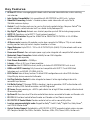
Key Features
› AV Over IP: Utilizes a managed gigabit network switch to enable video distribution, matrix switching,
and extension
› Inter-System Compatibility: Fully compatible with KD-IP922ENC and DEC units / systems
› Video Wall Processing: Encoder + Decoder systems create video walls with up to 16x16,
256 total maximum displays.
› Control: 2 multi-function ports may be used as third-party control interface, Compass Control
®
Pro
master controller, control extension via IP, or callable via KeyCode open API
› Key Digital
®
App Ready: Network scan & detect populates pre-built GUI including image preview
› HDCP 2.2: Compliancy up to HDCP 2.2 and backward compliant
› 4K/Ultra HD Resolution: Support for 4096x2160 or 3840x2160 24/25/30Hz at 4:4:4/8 Bit or
60Hz at 4:2:0/8 Bit
› 4K Down-scale: Incoming 4K resolution can be down-converted to 1080p or 720p
at each decoder,
enabling monitors to display content at optimal resolution at all times
› Signal Extension: Up to 330 ft. / 100 m @ 4K 24/25/30(4:4:4)/60(4:2:0) into network switch or or
point-to-point
› Power over Ethernet:
Does not require power supply when integrated with compatible PoE network switch
› Redundant Power Connection: Added reliability for non-PoE integration.
Power supply sold separately
› Data Stream Bandwidth: < 900Mbps
› Latency: <40ms at 4K. Less at lower resolution.
› Installation: Use KD-SMS16 to cleanly install up to twelve KD-IP822ENC/DEC units in rack
› HDMI
®
and HDCP Licensing: Fully licensed and compatible with HDCP 2.2 and HDMI latest
technology such as 4K/UHD 4:2:0/8bit at 60 f/s
› EDID Control: Internal library features 15 default EDID configurations and native EDID data from
Output/Display devices connected to Decoder
› Hot Plug Detection Control: Enables integrator to choose if active signal voltage is forced to
connected input devices
› Full Buffer System
™
: Manages TMDS re-clocking / signal re-generation, HDCP authentication with
source & display, EDID Control handshake, and Hot Plug control
› IR Sensor: Sensor powering via +5V IR In port collects line-of-sight IR from remote(s) without external
IR connecting block
› Up/Down IR:
Two channels of IR enable control to/from devices connected to Encoder and Decoder units
› RS-232: Bi-Directional control to/from Encoder and Decoder unit on Phoenix connector
› RS-232/TCP-IP Control Mode: Provides control of unit as well as connectivity status
› Lossless compressed digital audio: Support for Dolby
®
TrueHD, Dolby
®
Digital Plus, Dolby Atmos
®
,
and DTS-HD Master Audio
™
› Control System Support: Controllable by all IR, RS-232 & TCP/IP supported control systems via open
API: Compass Control
®
Pro, AMX
®
, Control4
®
, Crestron
®
, KNX
®
, RTI
®
, Savant, URC
®
, Leviton
®
etc.

2
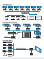
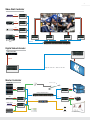
Digital Video Matrix:
HDMI
PCCable/Satellite Digital Signage
HDMI HDMIHDMI IR/RS232
Camera
TCP/IP
TCP/IP
TCP/IP
HDMI
RS232
HDMI
RS232
HDMI
RS232
HDMI
RS232
HDMI
RS232
HDMI
RS232
HDMI
RS232
WiFi Router
Managed Gigabit Switch
WiFi
KDMS
™
Pro
System Setup
System Control
Key Digital
®
App
KD-IP822ENC KD-IP822ENC KD-IP822ENC KD-IP822ENC
KD-IP822DEC KD-IP822DEC KD-IP822DEC KD-IP822DEC KD-IP822DEC KD-IP822DEC KD-IP822DEC
Digital Video Distribution System
WiFi Router
WiFi
Managed Gigabit Switch
HDMI
x10
IR/RS232
KD-IP822DEC
HDMI
x10
IR/RS232
KD-IP822DEC
HDMI
x10
IR/RS232
KD-IP822DEC
HDMI
x
10
IR/RS232
KD-IP822DEC
HDMI
x
16
IR/RS232
KD-IP822DEC
TCP/IP
TCP/IP
Digital Signage
HDMI
TCP/IP
KD-IP822ENC
System Control:
Compass Control
®
Pro App on iOS
Digital Video Switcher
Cable/Satellite
HDMI
RS-232
HDMI
HDMI
HDMI
HDMI
HDMI
HDMI
TCP/IP TCP/IP
KD-IP822ENC
KD-IP822ENC
KD-IP822ENC
KD-IP822ENC
KD-IP822ENC
KD-IP822DEC
Managed Gigabit Switch
RS-232
Laptop 1
Laptop 2
Dedicated PC
Laptop 3 (Local)
Document
Camera
Usage Modes

3
Video Wall Controller
TCP/IP
Signage PC 1
HDMI
KD-IP822ENC
Cable/Satellite
HDMI
IR/RS232
KD-IP822ENC
Digital Signage
HDMI
KD-IP822ENC
HDMI
RS232
KD-IP822DEC
HDMI
RS232
KD-IP822DEC
HDMI
RS232
KD-IP822DEC
HDMI
RS232
KD-IP822DEC
Operator Station
(PC)
HDMI
KD-IP822ENC
Digital Video Extender
Cable/Satellite
HDMI HDMI
TCP/IP
Up to 330 ft / 100 m @ 4K
KD-IP822ENC
KD-IP822DEC
Master Controller
Satellite (8)
Cable
Digital Signage
Music Streamer
Security Panel
Audio Amp
HDMI
TCP/IP
TCP/IP
IR
HDMI
IR/RS232
HDMI
HDMI
IR
IR
RS232
RS232
Audio
Audio
Speakers
Lighting
HDMI
IR/RS232
5V Voltage
Trigger
Managed Gigabit Switch
Dimmable Lights
Motorized Screen
Projector
Displays (14)
x14
x8
KD-IP822ENC
KD-IP822ENC
KD-IP822ENC
KD-IP822DEC
KD-IP822DEC

4
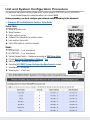
Unit and System Configuration Procedure
This procedure documents building a Video over IP system using KD-IP822ENCs and KD-IP822DECs.
» A less detailed video of the setup procedure can be found HERE
Before proceeding, you must configure your network switch according to this document:
› Enterprise AV Verified Network Switcher Setup Guide
Setup Steps:
1. Setup all Encoder units
2. Setup Decoders
3. Define switcher system
4. (Optional) Add Video Walls to switcher system
5. Load switcher file to units
6. Verify HDMI switcher system functionality
Needs:
1. KD-IP822ENC – 1 per video source
2. KD-IP822DEC – 1 per video display
3. Verified Network Switch – Configured according to VNS Setup Guide
4. PC with Key Digital Management Software
™
Pro
5. USB A to Micro – Included with KD-IP822
6. Completed KD-IP822 System Configuration Questionnaire (below)
7. Video Source – at least one
8. Video Display – at least one
Key Digital
®
App
on the App Store
KDMS
™
Pro
Download Page
KDMS
™
Download Page

5
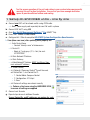
Test for proper operation of the unit and cables in your system before permanently
securing the unit for final installation. Ensure that you leave enough ventilation
space to provide sufficient airflow and cooling.
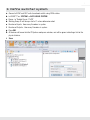
1. Setup all ENCODER units – one by one
a. Connect one ENC unit to network switch using CAT6 cable.
» i. Note: Power supply sold separately for non-PoE switch systems
b. Connect ENC to PC using USB
c. Open Key Digital Management Software
™
Pro (KDMS
™
Pro)
d. Detect unit: SCAN -> USB DEVICE
e. Configure Unit. Refer to completed KD-IP822 System Configuration Questionnaire.
› Save (blue save icon) after updating each property cell
» i. Enter Device Name
» Desired “friendly name” of video source
» ii. Device ID
» Begin at 1 and go up (2, 3, 4 etc) for each
KD-IP822ENC
» iii. Main Network IP Address
» iv. Main Gateway
» v. Video Network IP Address (MUST be different from
main network IP address)
» vi. Video Gateway
» vii. (Optional) if Compass Control
®
Pro will be used,
set Control Port 1, and Control Port 2:
» 1. Control Mode: Compass Control
» 2. Configuration: IR Output
» 3. Save
» viii. Review all settings are entered correctly
» ix. Perform a final save using the HARDDRIVE ICON
to ensure all settings are applied
f. Connect next Encoder
g. Repeat steps for each additional Encoder.
Ensure Device IDs and IP addresses are unique for each

6
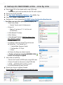
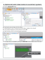
2. Setup all DECODER units – one by one
a. Connect one DEC unit to network switch using CAT6 cable.
» i. Note: Power supply sold separately for non-PoE switch systems
b. Connect DEC to PC using USB
c. Open Key Digital Management Software
™
Pro (KDMS
™
Pro)
d. Detect unit: SCAN -> USB DEVICE
e. Configure Unit. Refer to completed KD-IP822 System Configuration Questionnaire.
› Save (blue save icon) after updating each property cell
» i. Enter Device Name
» Desired “friendly name” of video source
» ii. Device ID
» Begin at 1 and go up (2, 3, 4 etc) for each
KD-IP822DEC
» iii. Main Network IP Address
» iv. Main Gateway
» v. Video Network IP Address (MUST be different from
main network IP address)
» vi. Video Gateway
» vii. (Optional) if Compass Control
®
Pro will be used,
set Control Port 1, and Control Port 2:
» 1. Control Mode: Compass Control
» 2. Configuration: IR Output
» 3. Save
» viii. Review all settings are entered correctly
» ix. Perform a final save using the HARDDRIVE ICON
to ensure all settings are applied
f. Verify video and switching
» i. Connect the Decoder to HDMI display using HDMI cable
» ii. Connect Encoder to video source using HDMI cable
» iii. SCAN -> NETWORK SCAN to ENCs and DEC
» iv. Use KDMS Control GUI area to switch
g. Repeat steps for each additional Decoder.
Ensure Device IDs and IP addresses are unique for each

7
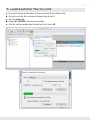
3. Define switcher system
a. Connect all ENC and DEC units to network switch using CAT6 cables
b. In KDMS
™
Pro: SYSTEM -> AUTO-BUILD SYSTEM
c. Name: ie “Dakota Dunes 17x29”
d. Starting Group ID will always start at 1 unless otherwise noted
e. Number of Inputs: How many Encoders in system
f. Number of Outputs: How many Decoders in system
g. Press OK
h. All devices will move into the IP System workspace window, and will be green indicating a link to the
physical device.
i. Save

8
4. (Optional) Add Video Walls to switcher system
a. Click the Add Video Wall button
b. Enter friendly name for video wall (ie East Lobby)
c. Starting Display is Device ID number of the top-left display / decoder in the video wall
d. Enter number of horizontal and vertical displays and press OK
e. Now the displays within the video wall appear as one output
f. The video wall may be controlled by pressing the VIDEO WALL button at bottom center of the screen.

9
5. Load switcher file to units
a. Ensure all Encoders and Decoders units are connected to the network switch
b. Ensure the switcher file is created and opened (refer to step 3)
c. Click the Load button
d. Choose ALL DEVICES in the devices drop down
e. After the switcher configuration file loads to all units, press OK

10
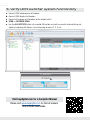
6. Verify HDMI switcher system functionality
a. Connect HDMI video sources to Encoders
b. Connect HDMI displays to Decoders
c. Connect all Encoders and Decoders to the network switch
d. SCAN -> NETWORK SCAN
e. Use the ALL OUTPUTS button in the control GUI section and verify successful video switching and
signal by beginning with Source 1 and advancing to source 2, 3, 4, etc.
Visit keydigital.com for a Complete Manual
Please visit www.keydigital.com for the full manual
and software downloads.

11
Important Product Warnings:
1. Connect all cables before providing power to the unit.
2. Test for proper operation before securing unit behind walls or in hard to access spaces.
3. If installing the unit into wall or mounting bracket into sheet-rock, provide proper screw support with
bolts or sheet-rock anchors.
Safety Instructions:
Please be sure to follow these instructions for safe operation of your unit.
1. Read and follow all instructions.
2. Heed all warnings.
3. Do not use this device near water.
4. Clean only with dry cloth.
5. Install in accordance with the manufacturer’s instructions.
6. Do not install near any heat sources such as radiators, heat registers, stoves, or other apparatus
(including amplifiers) that produce heat.
7. Only use attachments/accessories specified by the manufacturer.
8. Refer all servicing to qualified service personnel. Servicing is required when the device has been
damaged in any way including:
» Damage to the power supply or power plug
» Exposure to rain or moisture
Power Supply Use:
You MUST use the Power Supply PROVIDED with your unit or you VOID the Key Digital
®
Warranty
and risk damage to your unit and associated equipment.

12
Contacting Key Digital
®
Technical Support
For technical questions about using Key Digital
®
products, please contact us at:
› Phone: 914-667-9700
› E-mail: [email protected]
Repairs and Warranty Service
Should your product require warranty service or repair, please obtain a
Key Digital
®
Return Material Authorization (RMA) number by contacting us at:
› Phone: 914-667-9700
› E-mail: [email protected]
Warranty Information
All Key Digital
®
products are built to high manufacturing standards and should provide years of trouble-free
operation. They are backed by a Key Digital Limited 3 Year Product Warranty Policy.
http://www.keydigital.com/warranty.htm

13

Key Digital
®
, led by digital video pioneer Mike Tsinberg,
develops and manufactures high quality, cutting-edge
technology solutions for virtually all applications where
high-end video and control are important. Key Digital
®
is at the forefront of the video industry for Home
Theater Retailers, Custom Installers, System Integrators,
Broadcasters, Manufacturers, and Consumers.
Rev 1 – June 2020
Key Digital
®
:: 521 East 3rd Street :: Mount Vernon, NY 10553
Phone : 914.667.9700 Fax : 914.668.8666 Web : www.keydigital.com
© 2019 Key Digital, Inc. All rights reserved.
-
 1
1
-
 2
2
-
 3
3
-
 4
4
-
 5
5
-
 6
6
-
 7
7
-
 8
8
-
 9
9
-
 10
10
-
 11
11
-
 12
12
-
 13
13
-
 14
14
-
 15
15
-
 16
16


Key Digital KD-IP822ENC User guide
- Type
- User guide
- This manual is also suitable for
Ask a question and I''ll find the answer in the document
Finding information in a document is now easier with AI
Related papers
-
Key Digital KD-MS8x8G Quick setup guide
-
Key Digital KD-XWPS User guide
-
-
Key Digital KD-IP922DEC-II User guide
-
Key Digital KD-EXWPSTx User manual
-
-
-
-
-
Key Digital KD-MAX8x8 Operating instructions
Other documents
-
X10 Wireless Technology IN58A User manual
-
KEY DIGITAL APP READY Source and Display Control User manual
-
infobit iSwitch 265 User manual
-
-
VigilLink VL-IPHDKD-1 User manual
-
 Altimium ALT-IPD1080 User guide
-
 Altimium ALT-IPC1080 User guide
-
Raritan RAV-IP Distribution System User guide
-
AV Access HDIP100D User manual
-
DigiTech HEC150IPLV2 HDMI Over IP Extender User manual

