Page is loading ...

MODEL 1512
COMMAND PROCESSOR
BURGLARY/FIRE
CONTROL PANEL/COMMUNICATOR
INSTALLATION GUIDE
123
2841 E. Industrial Drive Springfield, MO 65802-6310 417-831-9362 LT-0138 (11/93)

MODEL 1512
COMMAND PROCESSOR
BURGLARY/FIRE
CONTROL PANEL/COMMUNICATOR
INSTALLATION GUIDE
FCC NOTICE
This equipment has been tested and found to comply with the limits for a Class A digital device, pursuant to Part 15
of the FCC Rules. These limits are designed to provide reasonable protection against harmful interference when the
equipment generates, uses, and can radiate radio frequency energy and, if not installed and used in accordance with
the instruction manual, may cause harmful interference to radio communications. Operation of this equipment in a
residential area is likely to cause harmful interference in which case the user will be required to correct the interference
at his own expense.
Copyright © 1992, 1993 Digital Monitoring Products, Incorporated
Information furnished by DMP is believed to be accurate and reliable.
This information is subject to change without notice.

TABLE OF CONTENTS
PRODUCT SPECIFICATIONS
Power Supply................................................................................................................ 1.1
Communication ............................................................................................................. 1.2
Protection Loops ........................................................................................................... 1.3
Keypad Control ............................................................................................................. 1.4
Enclosure Specifications............................................................................................... 1.5
Wiring Diagram ............................................................................................................. 1.6
Lightning Protection ...................................................................................................... 1.7
PRIMARY POWER SUPPLY
Terminals 1 and 2 ......................................................................................................... 2.1
Transformer .................................................................................................................. 2.2
SECONDARY POWER SUPPLY
Battery .......................................................................................................................... 3.1
System Ground ............................................................................................................. 3.2
Replacement Period ..................................................................................................... 3.3
Discharge/Recharge ..................................................................................................... 3.4
Battery Supervision....................................................................................................... 3.5
1512 Power Requirements ........................................................................................... 3.6
BELL OUTPUT
Terminal 5 ..................................................................................................................... 4.1
KEYPAD LOOP EXPANDER BUS
Description .................................................................................................................... 5.1
Terminal 7 - RED ..................................................................................................... 5.2
Terminal 8 - YELLOW.............................................................................................. 5.3
Terminal 9 - GREEN ................................................................................................ 5.4
Terminal 10 - BLACK ................................................................................................. 5.5
SMOKE DETECTOR OUTPUT
Terminal 11 ................................................................................................................... 6.1
Current Rating .............................................................................................................. 6.2
POWERED LOOP FOR 2-WIRE SMOKE DETECTORS
Terminals 12 and 13 ..................................................................................................... 7.1
PROTECTION LOOPS
Description .................................................................................................................... 8.1
Operational Parameters................................................................................................ 8.2
Loop Response Time.................................................................................................... 8.3
Keyswitch Arming Loop ................................................................................................ 8.4
TELEPHONE RJ CONNECTOR
Description .................................................................................................................... 9.1
FCC Registration .......................................................................................................... 9.2
Notification .................................................................................................................... 9.3
RESET JUMPER J16
Description .................................................................................................................. 10.1
PROGRAMMER CONNECTION
Description .................................................................................................................. 11.1
UNIVERSAL UL BURGLARY SPECIFICATIONS
Introduction ................................................................................................................. 12.1
Wiring.......................................................................................................................... 12.2
Control Outside Of Protected Area ............................................................................. 12.3
Police Station Phone Numbers ................................................................................... 12.4
Bypass Reports .......................................................................................................... 12.5
System Maintenance .................................................................................................. 12.6
UL 1023 SPECIFICATIONS
Bell Cutoff ................................................................................................................... 13.1
Entry Delay ................................................................................................................. 13.2
Exit Delay.................................................................................................................... 13.3
Section

TABLE OF CONTENTS
Section
UL 1610, 1076 SPECIFICATIONS
Opening/Closing Reports............................................................................................ 14.1
Closing Wait................................................................................................................ 14.2
Opening Code............................................................................................................. 14.3
Proprietary Dialer ........................................................................................................ 14.4
UL 1635 SPECIFICATIONS
System Trouble Display .............................................................................................. 15.1
Digital Dialer Telephone Number................................................................................ 15.2
Entry Delay ................................................................................................................. 15.3
Exit Delay.................................................................................................................... 15.4
Automatic Recall ......................................................................................................... 15.5
Closing Wait................................................................................................................ 15.6
System Test ................................................................................................................ 15.7
Grade B Central Station.............................................................................................. 15.8
UL 365, 609 SPECIFICATIONS
System Trouble Display .............................................................................................. 16.1
Entry Delay ................................................................................................................. 16.2
Grade A Bell ............................................................................................................... 16.3
Bell Cutoff ................................................................................................................... 16.4
Automatic Bell Test ..................................................................................................... 16.5
System Test ................................................................................................................ 16.6
Grade A Mercantile ..................................................................................................... 16.7
Mercantile Safe and Vault........................................................................................... 16.8
Line Security for Police Connect................................................................................. 16.9
UNIVERSAL UL, NFPA FIRE ALARM SPECIFICATIONS
Introduction ................................................................................................................. 17.1
Wiring.......................................................................................................................... 17.2
Transformer ................................................................................................................ 17.3
End of Line Resistor ................................................................................................... 17.4
System Trouble Display .............................................................................................. 17.5
Fire Display ................................................................................................................. 17.6
Police Station Phone Numbers ................................................................................... 17.7
System Maintenance .................................................................................................. 17.8
Audible Alarm ............................................................................................................. 17.9
Fire Loop Programming .............................................................................................. 17.10
UL 985 NFPA 74 SPECIFICATIONS
Bell Output Definition .................................................................................................. 18.1
System Test ................................................................................................................ 18.2
CALIFORNIA STATE FIRE MARSHAL SPECIFICATIONS
Bell Output Definition .................................................................................................. 19.1
System Test ................................................................................................................ 19.2

1512 INSTALLATION GUIDE
Digital Monitoring Products 1512 Installation Guide
Page 1
PRODUCT SPECIFICATIONS
1.1 Power Supply
Transformer Input 16 VAC 40VA
Battery Input 12 VDC 6.5Ah
Auxiliary 12 VDC output at 450mA
Bell Output 12 VDC at 1000mA
Inherent Power Limited
1.2 Communication
Built in dialer communication to DMP Model SCS-1 Receiver
Can operate as a local control
1.3 Protection Loops
Four Class B grounded 1K ý EOL loops
One Class B ungrounded 3.3K ý EOL powered loop with reset
1.4 Keypad Control
Four wire bus to a maximum of four keypads or two keypads and two loop expanders
Operates with DMP Model 670, 770, or 771 Alphanumeric Keypad
Operates with DMP Model 772, 773, or 774 Non-Alpha Keypad
Operates with DMP Model 704, 705, 714, and 715 Loop Expanders
1.5 Enclosure Specifications
The 1512 is shipped installed in its enclosure. The end of line resistors, battery leads, and programming
sheet are also included.
Size: 10.5" x 9.0" x 4"
Weight: 4 lbs.
Color: Grey
Construction: 20 gauge cold rolled steel

1512 INSTALLATION GUIDE
Digital Monitoring Products 1512 Installation Guide
Page 2
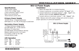
1.6 Wiring Diagram
The 1512 circuit board is shown below. Interconnection to the various modules is also shown as well as
locations of terminals and option jumpers. A full description for each is contained in this installation guide.
1.7 Lightning Protection
Metal Oxide Varistors and Transient Voltage Suppressors help protect against voltage surges on input and
output circuits of the 1512. Additional surge protection is available by installing the DMP Model 370 or
370RJ Lightning Suppressor.
AC BELL
AC
1234 567 89
10 11 12 13 14 15 16 17 18 19
GND RED YEL GRN BLKB + B - SMK L5+ L5- L1 L2 L3 L4GNDGND
1k Ω
3.3k Ω Resistor
DMP Model 309
1k Ω1k Ω
J16
Command Processor Reset
J9
1k Ω
1k Ω
1k Ω
1k Ω
3.3k Ω
3.3k Ω
3.3k Ω
3.3k Ω
LOOP EXPANDER
Model 705 or 715
25mA at 12 VDC
LOOP EXPANDER
Model 704 or 714
15mA at 12 VDC
Loop 5 compatibility identifier: A
Loop 5 maximum operating range:
8.8 VDC to 14.2 VDC.
Loops 5, 11 to 14, and 21 to 24 are
suitable for use with fire initiating devices.
RED
BLACK
22 GA. MIN GREEN
22 GA. MIN BLACK
YELLOW
22 GA. MIN RED
Maximum AC wire distance
With 16 gauge wire: 70 feet
With 18 guage wire: 40 feet
DMP transformers:
Model 320
16.5 VAC 40VA
wire in and
Model 321
16.5 VAC 40VA
Keypads
Model 670, 770, 771
100mA at 8 to 16 VDC
125mA with display lit.
Model 772, 773, 774
30mA at 8 to 16 VDC
Cold Water Pipe
Earth Ground Yellow
Red
Green
Black
16 to 18 gauge wire
Heat detectors, manual pull
stations or any other UL listed
shorting device. Unlimited
number of units.
Bell
Total current 1 Amp max.
Refer to LT-0164 for list
or approved indicating
devices.
NFPA 74
An alarm sounding device
must be installed indoors
so that it is clearly heard
in all sleeping areas.
Plug into
120 VAC
outlet not
controlled
by switch.
Keyswitch Arming Loop
See section 8.4.
May be connected to any loop.
+
Ð
1k Ω
DMP Model 310
Smoke
Detector
Power
Supervision
Relay
Secondary Power Supply
Use only 12 VDC rechargable
battery. DMP Model 367.
1.2 Amps max. charging current.
Replace every 3 to 5 years.
1k Ω
1k Ω
ARM
DISARM
1k Ω
1k Ω
Refer to LT-0164 for a list
of approved 4-wire smoke
detectors and power
supervision relays.
EPROM Socket
J3
Phone Line
Connector
Loop 1
Loop 2
Loop 3
Loop 4
Loop 5
J9 Programmer Connector
For Sprinkler Supervision
Normally Open supervisory
devices must be used.
22 GA. MIN
A maximum of four keypads or
loop expanders can be connected
to the 1512. Loops are available on
device addresses one and two only.
Up to 450mA auxiliary
current at 12 VDC from
terminal 7.
Tamper loop must be programmed as a Supervisory Type loop.
See section 13.7 in the 891A Programming Manual, LT-0120.
Tamper protection
when required for
Model 349A Attack
Resistant Enclosure.
Front Tamper
Rear Tamper

1512 INSTALLATION GUIDE
Digital Monitoring Products 1512 Installation Guide
Page 3
PRIMARY POWER SUPPLY
2.1 Terminals 1 and 2
Connect the transformer for the 1512 panel to terminals 1 and 2 at the bottom left hand side of the circuit
board. Use a minimum 16 to18 gauge wire between the transformer and the panel.
2.2 Transformer
The 1512 is powered by a 16.5 VAC 40VA transformer. The transformer must be plugged into an
unswitched 120 VAC 60 Hz commercial power outlet.
Never share the transformer output with any other equipment.
SECONDARY POWER SUPPLY
3.1 Battery
Connect the battery leads supplied with the panel to terminals 3 and 4. Connect a DMP Model 367, 12
VDC 6.5Ah sealed lead-acid rechargeable battery to the battery leads. Terminal 3 is the positive terminal.
Observe polarity when connecting the battery.
A second battery can be connected to the panel by using a Model 318 dual battery harness. Use only
sealed lead-acid rechargeable batteries supplied by DMP or manufactured by Eagle Picher or Yuasa to
ensure proper charging.
DO NOT USE GEL CELL BATTERIES.
3.2 System Ground
Terminal 4 of the panel must be connected to earth ground to provide transient suppression. A cold water
pipe or ground rod is recommended. An electrical conduit ground is not recommended. Use a minimum 14
gauge wire for grounding.
3.3 Replacement Period
Digital Monitoring Products recommends the battery be replaced every 3 to 5 years under normal use.
3.4 Discharge/Recharge
The 1512 battery charging circuit is a float charge of 13.9 VDC at a maximum current of 1.2 Amps. The
total current available is reduced by the total auxiliary power draw from terminals 6 and 11. The various
battery voltage levels are listed below.
Battery Trouble 11.9 VDC
Battery Restored 12.6 VDC
3.5 Battery/Supervision
The 1512 tests the battery once every hour when AC power is present. The test is done at 15 minutes past
the hour and lasts five seconds. A load is placed on the battery and if the battery voltage falls below 11.9
VDC a low battery is detected. If AC power has failed, a low battery is detected when the battery voltage
falls below 11.9 VDC.
If a low battery is detected while AC power is present, the test is repeated every two minutes until the
battery reaches a restored voltage of 12.6 VDC. If a low battery is replaced with a fully recharged battery,
the restored battery is not detected until the next two minute test.

1512 INSTALLATION GUIDE
Digital Monitoring Products 1512 Installation Guide
Page 4
Cannot Exceed 13.0 with Two 367 Batteries
Cannot Exceed 6.5 with One 367 Battery
Number of standby
hours required
130mA
1.6mA
4mA
.1mA
.08mA
.05mA
125mA
1.6mA
30mA
1.6mA
7mA
1.6mA
7mA
.1mA
.08mA
.05mA
4mA
130mA
*2mA
30mA
.1mA
.08mA
.05mA
Bell Output 1000mA max.
125mA
20mA
*2mA
30mA
20mA
*2mA
7mA
*2mA
7mA
.1mA
.08mA
.05mA
*9mA
.001
mA
3.6 1512 Power Requirements
During AC power failure, the 1512 panel and all connected auxiliary devices draw their power from the
battery. All devices must be taken into consideration when calculating the standby capacity of the battery.
Below is a list of the current requirements of the 1512 panel and various accessory devices. Add the
additional current draw of ALL devices used in the system for the total current required. The total is then
multiplied by the total number of standby hours required by the standard to give you the total ampere/hours
required.
1512 STANDBY BATTERY POWER CALCULATIONS
Standby Current Alarm Current
1512 Control Unit ______ ______
Active Loops 1 to 4 Qty _____ x ______ Qty _____ x ______
Active Loop 5 ______ ______
BRK Smoke Detectors Qty _____ x ______ Qty _____ x ______
DS Smoke Detectors Qty _____ x ______ Qty _____ x ______
ESL Smoke Detectors Qty _____ x ______ Qty _____ x ______
______
670, 770, 771 Keypads Qty _____ x ______ Qty _____ x ______
Annunciator (ON) Qty _____ x ______
Active Loops Qty _____ x ______ Qty _____ x ______
772, 773, 774 Keypads Qty _____ x ______ Qty _____ x ______
Annunciator (ON) Qty _____ x ______
Active Loops Qty _____ x ______ Qty _____ x ______
704 Loop Expander Qty _____ x ______ Qty _____ x ______
Active Loops Qty _____ x ______ Qty _____ x ______
705 Loop Expander Qty _____ x ______ Qty _____ x ______
BRK Smoke Detectors Qty _____ x ______ Qty _____ x ______
DS Smoke Detectors Qty _____ x ______ Qty _____ x ______
ESL Smoke Detectors Qty _____ x ______ Qty _____ x ______
Active Loops Qty _____ x ______ Qty _____ x ______
Aux. Powered Devices (Terminal 7) ______ ______
(Other than 670, 770, 771, 772, 773, 774, 704, 705)
Total Standby ______mA Total Alarm ______
* Based on 10% of active loops in alarm condition
Total Standby _________mA x __________= _________mA/hours
Total Alarm + _________mA/hours
Total _________mA/hours
x _________
= _________ Ampere/Hours Required

1512 INSTALLATION GUIDE
Digital Monitoring Products 1512 Installation Guide
Page 5
BELL OUTPUT
4.1 Terminal 5
Nominal 12 VDC is supplied by the panel at terminal 5 for powering an alarm bell or horn. The output is
rated for a maximum of 1 Amp. This output can be steady or pulsed depending upon the Bell Action
specified in Output Options. Terminal 6 is the common for the bell circuit. See the wiring diagram in section
1.6 for a list of compatible devices.
KEYPAD, LOOP EXPANDER BUS
5.1 Description
All DMP Security Command keypads and loop expanders connect to the panel through a four conductor
cable. The conductors connect to terminals 7,8,9, and 10. The maximum length of all cables connecting
keypads and loop expanders to the 1512 is 500 feet using at least 22 gauge wire for all runs. The maximum
distance can be increased to 1,000 feet using 18 gauge for each conductor.
Any combination of keypads and loop expanders can be used with only those loops on addresses one and
two being programmable. The 1512 does not provide for loops on addresses three and four.
5.2 Terminal 7 - RED
Nominal 12 VDC is supplied at terminal 7 to power Security Command keypads and loop expanders.
Terminal 7 also supplies power for auxiliary devices. Terminal 10 is the common for terminal 7 and terminal
11. The maximum output is rated at 450mA. The output current is shared with the smoke detector output on
terminal 11 and terminal 12 (loop 5). All devices totaled together must not exceed 450mA.
5.3 Terminal 8 - YELLOW
Terminal 8 is data receive from Security Command keypads and loop expanders. It cannot be used for any
other purpose.
5.4 Terminal 9 - GREEN
Terminal 9 is data transmit to Security Command keypads and loop expanders. It cannot be used for any
other purpose.
5.5 Terminal 10 - BLACK
Terminal 10 is the common reference for Security Command keypads, loop expanders, and any auxiliary
devices powered from terminal 7.
SMOKE DETECTOR OUTPUT
6.1 Terminal 11
Nominal 12 VDC is supplied at terminal 11 to power 4-wire smoke detectors or other latching devices. This
output can be turned off for five seconds by the user to reset the detectors. Use the Fire Reset Menu
Option accessible through the Security Command keypad. Terminal 10 is the common for the smoke
detector circuit and auxiliary power. Refer to LT-0164 for a list of compatible 4-wire smoke detectors.
6.2 Current Rating
The Smoke Detector Output current is shared with the auxiliary power supply from terminal 7 as described
in section 5.2. The total current draw for all 4-wire smoke detectors must be included with terminal 7
calculations and must not exceed 450mA.

1512 INSTALLATION GUIDE
Digital Monitoring Products 1512 Installation Guide
Page 6
POWERED LOOP FOR 2-WIRE SMOKE DETECTORS
7.1 Terminals 12 and 13
The 1512 panel provides a 2-wire Style A ungrounded powered loop on terminals 12 and 13. Terminal 12 is
the positive side of the loop. When programming, terminals 12 and 13 are referred to as loop number 5.
Loop 5 uses a Model 309, 3.3K ý EOL resistor provided with the panel. The powered loop has an
operating range of 8.8 to 14.2 VDC and a compatibility identifier of: A. The loop is compatible with the
following detectors.
PROTECTION LOOPS
8.1 Description
The four protection loops provided on the 1512 panel are all grounded burglary loops. For programming
purposes the loops are numbered 1 through 4. Terminals 14 to 19 provide connection as listed below:
Terminal Function
14 Loop 1 voltage sensing
15 Ground for loops 1 and 2
16 Loop 2 voltage sensing
17 Loop 3 voltage sensing
18 Ground for loops 3 and 4
19 Loop 4 voltage sensing
The sensing terminal measures the voltage flowing through a 1000 ohm end-of-line resistor to ground. Dry
contact sensing devices can be used in series (normally-closed) or in parallel (normally-open) with any of
the burglary protection loops.
8.2 Operational Parameters
Each protection loop detects three conditions: open, normal, and short. The voltage ranges for each are
listed below:
Condition Resistance on loop Voltage on sensing terminal
Open over 1300 ohms over 2.0 VDC
Normal 600 to 1300 ohms 1.2 to 2.0 VDC
Short under 600 ohms under 1.2 VDC
1K
NORMALLY CLOSED CONTACTS NORMALLY OPEN CONTACTS COMBINATION: NORMALLY OPEN AND
NORMALLY CLOSED CONTACTS
1K
1K
_______________________________________________
_______________________________________________
_______________________________________________
_______________________________________________
_______________________________________________
_______________________________________________
_______________________________________________
_______________________________________________
Detect Base # of
Man. Model Id Base Id. Det.
BRK 1400 A 12
BRK 1451 A B401 or B401B A 10
BRK 1451DH A DH400 A 10
BRK 2400,2400TH A 10
BRK 2451, 2451TH A B401 or B401B A 10
BRK 2451 A DH400 A 10
DS DS200/DS200HD A MB200-2W A 15
ESL 422C/422CT S10P 25
RA-400 MAY BE USED ON ALL BRK DETECTORS
USE 330 OHM RESISTOR IN MB200-2W BASE
DIFFERENT DETECTOR MODELS MAY NOT BE MIXED

1512 INSTALLATION GUIDE
Digital Monitoring Products 1512 Installation Guide
Page 7
8.3 Loop Response Time
A condition must be present on a loop for 300 milliseconds before being detected by the panel. Ensure
that all detection devices used on the protection loops are rated for use with this delay. The loops can be
programmed for a fast response delay of 100 milliseconds.
8.4 Keyswitch Arming Loop
A loop programmed as an Arming Type, arms selected areas when placed into a shorted condition. The
selected areas are disarmed when placed into a normal (1K ý EOL) condition. If the loop is placed into an
open condition from a normal, or disarmed condition, a trouble is reported. If the loop is placed into an open
condition from a shorted (armed) condition, an alarm is reported and the loop is disabled until another
disarming occurs within the system. The areas controlled by the loop are selected with the 891/891A
Programmer.
TELEPHONE RJ CONNECTOR
9.1 Description
The connection to the switched telephone network is made by installing the DMP Model 356 RJ Cable into
socket J3 located at the top left hand corner of the circuit board.
9.2 FCC Registration
The Model 1512 complies with FCC part 68 and is registered with the FCC.
Registration number: CCKUSA-18660-AL-R Ringer Equivalence: 0.6B
9.3 Notification
Registered terminal equipment must not be repaired by the user. In case of trouble, the device must be
immediately unplugged from the telephone jack. The factory warranty provides for repairs. Registered
terminal equipment may not be used on party lines or in connection with coin telephones. Notification must
be given to the telephone company of:
a. The particular line(s) to which the service is connected
b. The FCC registration number
c. The ringer equivalence
d. The make, model, and serial number of the device
RESET JUMPER J16
10.1 Description
The reset jumper is located just to the right of the programmer connector and is used to reset the panel's
microprocessor. Install the jumper before applying power to the panel. Remove the jumper once power has
been applied for proper system operation.
PROGRAMMER CONNECTION
11.1 Description
One 40 pin header is provided for connecting a DMP Model 891/891A Programmer. The connector is
located in the top right hand side of the circuit board. The Model 891/891A Programming Manual (LT-0120)
provides complete instructions on the operation of the programmer.

1512 INSTALLATION GUIDE
Digital Monitoring Products 1512 Installation Guide
Page 8
UNIVERSAL UL BURGLARY SPECIFICATIONS
12.1 Introduction
The programming and installation specifications contained in this section must be completed when
installing the Model 1512 in accordance with any of the UL burglary standards. Additional specifications
may be required by a particular standard.
12.2 Wiring
All wiring must be in accordance with NEC, ANSI/NFPA 70-1984, UL 681, and UL 611 for all burglary
installations.
12.3 Control Outside of Protected Areas
A Potter EVD or Sentrol 5402 should be used in place of a lined cabinet when the panel is installed outside
of the protected area.
12.4 Police Station Phone Numbers
The digital dialer telephone number programmed for communication must not be a police station phone
number unless that phone number is specifically provided for that purpose.
12.5 Bypass Reports
The Bypass Reports option must be programmed as YES for all UL burglary applications. See section 7.5
of the 891/891A Programming Manual.
12.6 System Maintenance
Proper installation and regular maintenance by the installing alarm company and frequent testing by the
end user is essential to ensure continuous satisfactory operation of any alarm system. Offering a
maintenance program and acquainting the user with the correct procedure for use and testing of the
system is also the responsibility of the installing alarm company.
UL 1023 SPECIFICATIONS
Household Burglar-Alarm System Units
13.1 Bell Cutoff
The bell cutoff time cannot be less than five minutes. See section 9.2 of the 891/891A Programming
Manual.
13.2 Entry Delay
The maximum entry delay must not be more than 45 seconds. See sections 8.9 and 8.10 of the 891/891A
Programming Manual.
13.3 Exit Delay
The maximum exit delay must not be more than 60 seconds. See section 8.11 of the 891/891A
Programming Manual.

1512 INSTALLATION GUIDE
Digital Monitoring Products 1512 Installation Guide
Page 9
UL 1610, 1076 SPECIFICATIONS
Central-Station and Proprietary Burglar-Alarm Units
14.1 Opening/Closing Reports
The Opening/Closing Reports option must be programmed as YES. See section 7.2 of the 891/891A
Programming Manual.
14.2 Closing Wait
The Closing Wait option must be programmed as YES. See section 8.6 of the 891/891A Programming
Manual.
14.3 Opening Code
The Opening Code option must be programmed as YES. See section 8.4 of the 891/891A Programming
Manual.
14.4 Proprietary Dialer
The Model 1512 provides Grade A Proprietary service when configured as a digital dialer.
UL 1635 SPECIFICATIONS
Digital Burglar Alarm Communicator System Units
15.1 System Trouble Display
The Status List Display must include at least one keypad that displays system monitor troubles. See
section 11.3 of the 891/891A Programming Manual.
15.2 Digital Dialer Telephone Number
Both telephone numbers programmed must begin with a D or P. See section 3.6B and 3.6C of the 891/891A
Programming Manual.
15.3 Entry Delay
The maximum entry delay used must not be more than 60 seconds. See sections 8.9 and 8.10 of the
891/891A Programming Manual.
15.4 Exit Delay
The maximum exit delay used must not be more than 60 seconds. See section 8.11 of the 891/891A
Programming Manual.
15.5 Automatic Recall
An automatic recall time must be entered so that the Model 1512 will transmit the automatic recall message
once per day. See sections 3.6D,E and F of the 891/891A Programming Manual.
15.6 Closing Wait
The Closing Wait option must be programmed as YES. See section 8.6 of the 891/891A Programming
Manual.
15.7 System Test
The System Test menu option must be programmed as YES. See section 10.12 of the 891/891A
Programming Manual.
15.8 Grade B Central Station
Grade B Central Station service can be provided under UL 1635 by adding a Grade A Local audible signal
appliance and placing the Model 1512 control into the Model 349A Grade A Attack Resistant Housing.

1512 INSTALLATION GUIDE
Digital Monitoring Products 1512 Installation Guide
Page 10
UL 365, 609 SPECIFICATIONS
Police Station Connected and Local Burglar Alarm Units and Systems
16.1 System Trouble Display
The Status List display must include at least one keypad that displays system monitor troubles. See
section 11.3 of the 891/891A Programming Manual.
16.2 Entry Delay
The maximum entry delay used must not be more than 60 seconds when using the Model 349A Grade A
housing. See section 8.9 and 8.10 of the 891/891A Programing Manual.
16.3 Grade A Bell
A Grade A Local audible signal appliance must be used.
16.4 Bell Cutoff
The bell cutoff time cannot be less than 15 minutes. See section 9.2 of the 891/891A Programming Manual.
16.5 Automatic Bell Test
The Automatic Bell Test option must be programmed as YES. See section 9.3 of the 891/891A Programming
Manual.
16.6 System Test
The System Test menu option must be programmed as YES. See section 10.12 of the 891/891A
Programming Manual.
16.7 Grade A Mercantile
For Grade A Mercantile and Police Station Connect operation the Model 1512 must be mounted in a
349A Grade A Attack Resistant Housing.
16.8 Mercantile Safe and Vault
When the DMP Model 349A housing is used, the Model 1512 provides operation as a Mercantile Safe
and Vault alarm. Bell Supervision and wiring must be in accordance with UL 681. If the Model 1512 is
mounted outside the safe or vault, tamper protection and the Sentrol Model 5402 or Potter EVD listed
vibration detectors should be used. The Model 1512 does not provide operation as a Bank Safe and Vault
alarm.
16.9 Line Security for Police Connect
Basic line security is provided when the Model 1512 is configured as a dialer system. High line security is
provided when configured as a multiplex system.

1512 INSTALLATION GUIDE
Digital Monitoring Products 1512 Installation Guide
Page 11
UNIVERSAL UL, NFPA FIRE ALARM SPECIFICATIONS
17.1 Introduction
The programming and installation specifications contained in this section must be completed when
installing the Model 1512 in accordance with any of the UL Fire standards or NFPA Codes. Additional
specifications may be required by a particular standard.
17.2 Wiring
All wiring must be in accordance with NEC, ANSI/NFPA 70-1984.
17.3 Transformer
A wire-in transformer should be used. DMP Model 320 16 VAC 40VA.
17.4 End of Line Resistor
The DMP Model 310 1K ý EOL resistor should be used on all 1K EOL fire loops. The DMP Model 309 3.3K
ý EOL resistor should be used on all 2-wire smoke detector loops.
17.5 System Trouble Display
The Status List display must include at least one keypad that displays system monitor troubles. See section
11.3 of the 891/891A Programming Manual.
17.6 Fire Display
The Status List display must include at least one keypad that displays troubles and alarms on fire type
loops. See section 11.4 of the 891/891A Programming Manual.
17.7 Police Station Phone Numbers
The digital dialer telephone number programmed for communication must not be a police station phone
number unless that phone number is specifically provided for that purpose.
17.8 System Maintenance
Proper installation and regular maintenance by the installing alarm company and frequent testing by the
end user is essential to ensure continuous satisfactory operation of any alarm system. Offering a
maintenance program and acquainting the user with the correct procedure for use and testing of the
system is also the responsibility of the installing alarm company.
17.9 Audible Alarm
When an audible alarm is used in a fire application, Fire Type loops should be programmed for Bell Action.
The bell action for fire type loops should not be programmed as N. See section 9.4 and 9.4A in the 891/
891A Programming Manual.
17.10 Fire Loop Programming
Fire loops must be programmed to activate a trouble on open conditions and an alarm on short conditions.
The swinger bypass function must not be used on any fire loops. If a retard is used on a waterflow loop it
cannot exceed 60 seconds and any retard in the waterflow initiating devices must be subtracted from the
60 seconds allowed. See sections 13.4 through 13.14 in the 891/891A Programming Manual. The retard
delay should not be used on a loop with smoke detectors.

1512 INSTALLATION GUIDE
Digital Monitoring Products 1512 Installation Guide
Page 12
UL 985, NFPA 74 SPECIFICATIONS
Household Fire Warning System Units
18.1 Bell Output Definition
The bell output of the Model 1512 must be programmed to operate steady on burglary alarms and pulsed
on fire alarms. See sections 9.4A and 9.4B of the 891/891A Programming Manual.
18.2 System Test
The System Test option must be programmed as YES. See section 10.12 of the 891/891A Programming
Manual.
CALIFORNIA STATE FIRE MARSHAL SPECIFICATIONS
19.1 Bell Output Definition
The bell output of the Model 1512 must be programmed to operate steady on burglary alarms and pulsed
on fire alarms. See sections 9.4A and 9.4B of the 891/891A Programming Manual.
19.2 System Test
The System Test option must be programmed as YES. See section 10.12 of the 891/891A Programming
Manual.
123
2841 E. Industrial Drive Springfield, MO 65802-6310 800-641-4282
/