Page is loading ...

INSTALLATION INSTRUCTIONS
FOR P4305-084/P4305-467
WARNING! SHUT POWER OFF AT FUSE OR CIRCUIT BREAKER.
AVERTISSEMENT! COUPER LE COURANT AU NIVEAU DES FUSIBLES OU DU DISJONCTEUR.
RAIL SYSTEM
CAUTION: Before you begin installing
Installing your Rail System your new rail system; disconnect the
READ THESE INSTALLATION INSTRUCTIONS power by removing the fuses or turning
BEFORE YOU BEGIN INSTALLING THIS NEW off the circuit breakers.
RAIL SYSTEM.
THIS SYSTEM MAY BE DIMMED WITH THE APPROPRIATE
C-L (CFL & LED) TYPE WALL DIMMER SWITCH.
A. Package Contents
1. Use a 60W Magnetic Transformer with this system
Models: P4305-084/P4305-467
(supplied).
2.Make sure all connections are tight and secure.
Unpack your new rail system; you should have the following;
3.Do not install any components of this system A- Rail track, B- Transformer, C- Ceiling standoffs, D- Fixtures
to any metal surface.
E & F- PE bag of mounting hardware including spare parts.
4. For use with models P4305 rail systems only.
Model: P4305
Tools needed for Installation:
Phillips Screwdriver, Flat Head Screwdriver,
Hammer, Wire Cutters, Allen wrench.
Rail System: Use only with electrical fittings identified
for use with the P4305 rail systems.
TRACK SYSTEM(to be only used with the
electrical fitting identified for use with the
P4305 track system)
Table of Contents
A. Package Contents pg. 1
B. Installing the Transformer pg. 2
C. Preparing the Rail sections for
6 p B g
Installation. pg. 3
D. Installing the Rails to the Ceiling
pgs. 3 & 4
E. Securing the Rail to the Ceiling pg. 5
F. Installing the Swivel Fixtures pg. 6
G.Restoring the Electical Power
pg. 6
H. Important Safety Instructions
pg. 7
This track system is to be supplied by a single
branch circuit of 120 volts,single phase. Not
intended for use with a powersupply cord or
convenience receptacle adapter.
This track is only to be used with other
6 b g
electrical fittings identified for use with the track system.
Page1-7

INSTALLATION INSTRUCTIONS
FOR P4305-084/P4305-467
WARNING! SHUT POWER OFF AT FUSE OR CIRCUIT BREAKER.
AVERTISSEMENT! COUPER LE COURANT AU NIVEAU DES FUSIBLES OU DU DISJONCTEUR.
Installing the Transformer
Step 5-1. Connect the white (neutral) wire from
NOTE : The transformer can be installed at any location
the transformer to the white wire from the junction box .
within 22' length of the track. For example , you can use a wire nut to secure the connection.(Fig,5)
install the transformer at one end or in the middle of the
Step 5-2. Connect the black (hot) wire from the
Choose a location that is most suitable for
transformer to the black wire from the junction box
electrical connections and appearance for the installation use a wire nut to secure the connection. (Fig.5)
of the transformer.
Secure wire connections with the 3 plastic wire nuts
Step 1. Locate transformer (a) and transformer
provided (Fig.5A)
mounting hardware package in box(A) which
contains 2pcs screws and 3pcs wire nuts. (Fig.1)
Step 2.Remove and set aside the 3 screws from
the transformer to release the back plate.(Fig.2)
Step 6.Tuck the wire nut connections into the electrical
junction box. Slide the transformer housing up until the
holes line up to the back plate,make sure all wires
Step 3. Line up the back plate with the junction box
are tucked in.secure it in place with the 3 screws
holes and secure with the two
previously removed.
junction box screws provided. (Fig.3)
Note: 1. MAKE SURE THAT THE STAND OFF IS IN
ALIGNMENT WITH THE RAIL.
Step 4.Connect the bare (ground) wire for the
transformer to the bare or green ground wire from the
junction box and use a wire nut to secure the connection
2. Transformer is equipped with a circuit breaker.
(Fig.4)
It is located on the side of the upper setcion of the
transformer. This will "trip" (turn off power) if too
many fixtures are put on the track or there is a short
circuit. To reset circuit breaker push button in.
If it continues to trip make sure that the total wattage
of all fixture does not exceed 60 watts. Also make
sure there is no conducting material shorting
out the track.
Page
2-7
A
a
Stand off
FIXTURE
WIRES
Black or
Smooth
HOUSE
WIRES
Black
(Hot)
FIXTURE
WIRES
White or
Ribbed
HOUSE
WIRES
White
(Neutral)
FIXTURE
WIRES
Bare
Copper
(Ground)
HOUSE
WIRES
Green
(Ground)
Fig.1
Fig.2
Fig.3
Fig.4
Fig.5
Fig.5A
Citcuit Breaker

INSTALLATION INSTRUCTIONS
FOR P4305-084/P4305-467
WARNING! SHUT POWER OFF AT FUSE OR CIRCUIT BREAKER.
AVERTISSEMENT! COUPER LE COURANT AU NIVEAU DES FUSIBLES OU DU DISJONCTEUR.
C.
Preparing the Rail Sections for Installation
D.
Installing the Rails to the Ceiling
Step 1.
Locate the three sections of rail and joiners
Step 1.
Locate the four standoffs and mounting hardware
packet (A), which contains the one allen wrench and several packet (B) which contains 4 screws, one allen wrench,
extra set screws. 4pcs drywall anchors and 4pcs threaded washers
Step 2. If you would like to customise the length of the rails, Step 2. Lay the assembled rail on the floor directly under
use a hacksaw to cut to the desired length. Use a file or the transformer.
equivalent to remove any burs from the rails. Remove
and replacethe end caps to the ends of the rails.
(A).End cap
Step 3. To bend or curve the rail, follow step 4, If the Step 3. The transformer and the standoffs will be used
rail will be mounted as a straight run, skip to step 5. to support the rail from the ceiling providing a total of
five supports. Use a pencil and tape measure to mark
Step 4. Use a round kitchen tabletop or similar
two of the support locations on the rail 6" from each end
household item as a template to bend the rail. Carefully of the rail.
hold the rail with one hand starting from the center
and working towards the ends. Table Top (A), Waste
Paper Basket (B), Counter Top (C)Plywood Template (D)
Step 5.
Secure the pieces of rail together by inserting
the ends of the rail firmly into the rail joiners. Tighten
the allen set screws with the allen wrench provided.
CAUTION/ PRECAUCION:DO NOT OVER TIGHTEN
ALLEN SET SCREWS.
Page3-7
d3.The transformer and the standoffs will be used to
support the rail from the ceiling,providing a totalof
five supports.Using a pencil and tape measure,mark
two of the support locations on the rail 6" from each
end of the rail.
d2.Lay the assembled rail on the floor directly under
the transformer.
d1.Locate the four standoffs and the standoff nounting
hardware packet,which contains(4)screws,(I)allen
wrench,(4)drywall anchors and (4)threaded washers.
c5.Secure the pieces of rail together by pushing the
ends of the rail firmly into the rail joiners.
Tighten the screws until the rail joinersis secure.
c3.To bend or curve the rail,follow step c4.If the rail will
be mounted as a straight run,skip to step c5.
3
c1.Locate the three pieces of rail and the rail joiner
packet,which contains (2)rail joiners,(I)allen wrench
and several extra set screws.
C.Prepare the Rail
c2.If you would like to shorten the length of the rail
system the rail can be cut with a hacksaw.End caps can
be removed and placed over the cut end of the rail.
c4.Use a round kitchen tabletop or similar household item
as a template to bend the rail.hold the rail,one hand
starting from the center and working towards the ends.
bend each section of the rail separately before
joining the rail sections together.
D.install the mounting hardware
RAIL JOINERS
PLYWOOD
TEMPLATE
TABLE TOP
WASTE PAPER
BASKET
COUNTER TOP
END CAP
RAIL JOINER
(4)STANDOFFS
STANDOFFS
MOUNTING
HARDWARE
d 3 . T h e t r a n s f o r m e r a n d t h e s t a n d o f f s w i l l b e u s e d t o
s u p p o r t t h e r a i l f r o m t h e c e i l i n g , p r o v i d i n g a t o t a l o f
f i v e s u p p o r t s . U s i n g a p e n c i l a n d t a p e m e a s u r e , m a r k
t w o o f t h e s u p p o r t l o c a t i o n s o n t h e r a i l 6 " f r o m e a c h
e n d o f t h e r a i l .
d 2 . L a y t h e a s s e m b l e d r a i l o n t h e f l o o r d i r e c t l y u n d e r
t h e t r a n s f o r m e r .
d 1 . L o c a t e t h e f o u r s t a n d o f f s a n d t h e s t a n d o f f n o u n t i n g
h a r d w a r e p a c k e t , w h i c h c o n t a i n s ( 4 ) s c r e w s , ( I ) a l l e n
wrench,(4)drywall anchors and (4)threaded washers.
c 5 . S e c u r e t h e p i e c e s o f r a i l t o g e t h e r b y p u s h i n g t h e
e n d s o f t h e r a i l f i r m l y i n t o t h e r a i l j o i n e r s .
T i g h t e n t h e s c r e w s u n t i l t h e r a i l j o i n e r s i s s e c u r e .
c 3 . T o b e n d o r c u r v e t h e r a i l , f o l l o w s t e p c 4 . I f t h e r a i l w i l l
b e m o u n t e d a s a s t r a i g h t r u n , s k i p t o s t e p c 5 .
3
c 1 . L o c a t e t h e t h r e e p i e c e s o f r a i l a n d t h e r a i l j o i n e r
p a c k e t , w h i c h c o n t a i n s ( 2 ) r a i l j o i n e r s , ( I ) a l l e n w r e n c h
a n d s e v e r a l e x t r a s e t s c r e w s .
C . P r e p a r e t h e R a i l
c 2 . I f y o u w o u l d l i k e t o s h o r t e n t h e l e n g t h o f t h e r a i l
s y s t e m t h e r a i l c a n b e c u t w i t h a h a c k s a w . E n d c a p s c a n
b e r e m o v e d a n d p l a c e d o v e r t h e c u t e n d o f t h e r a i l .
c 4 . U s e a r o u n d k i t c h e n t a b l e t o p o r s i m i l a r h o u s e h o l d i t e m
a s a t e m p l a t e t o b e n d t h e r a i l . h o l d t h e r a i l , o n e h a n d
s t a r t i n g f r o m t h e c e n t e r a n d w o r k i n g t o w a r d s t h e e n d s .
b e n d e a c h s e c t i o n o f t h e r a i l s e p a r a t e l y b e f o r e
j o i n i n g t h e r a i l s e c t i o n s t o g e t h e r .
D . i n s t a l l t h e m o u n t i n g h a r d w a r e
R A I L J O I N E R S
PLYWOOD
TEMPLATE
T A B L E T O P
W A S T E P A P E R
BASKET
COUNTER TOP
E N D C A P
R A I L J O I N E R
( 4 ) S T A N D O F F S
S T A N D O F F S
M O U N T I N G
H A R D W A R E
d3.The transformer and the standoffs will be used to
support the rail from the ceiling,providing a totalof
five supports.Using a pencil and tape measure,mark
two of the support locations on the rail 6" from each
end of the rail.
d2.Lay the assembled rail on the floor directly under
the transformer.
d1.Locate the four standoffs and the standoff nounting
hardware packet,which contains(4)screws,(I)allen
wre nch,(4)drywall anchors and (4)threaded washers.
c5.Secure the pieces of rail together by pushing the
ends of the rail firmly into the rail joiners.
Tighten the screws until the rail joinersis secure.
c3.To bend or curve the rail,follow step c4.If the rail will
be mounted as a straight run,skip to step c5.
c1.Locate the three pieces of rail and the rail joiner
packet,which contains (2)rail joiners,(I)allen wrench
and several extra set screws.
C.Prepare the Rail
c2.If you would like to shorten the length of the rail
system the rail can be cut with a hacksaw.End caps can
be removed and placed over the cut end of the rail.
A
D
A
B
C
A
A
A
B
c4.Use a round kitchen tabletop or similar household item
as a template to bend the rail.hold the rail,one hand
starting from the center and working towards the ends.
bend each section of the rail separately before
joining the rail sections together.
D.install the mounting hardware
d3.The transformer and the standoffs will be used to
support the rail from the ceiling,providing a totalof
five supports.Using a pencil and tape measure,mark
two of the support locations on the rail 6" from each
end of the rail.
d2.Lay the assembled rail on the floor directly under
the transformer.
d1.Locate the four standoffs and the standoff nounting
hardware packet,which contains(4)screws,(I)allen
wrench,(4)drywall anchors and (4)threaded washers.
c5.Secure the pieces of rail together by pushing the
ends of the rail firmly into the rail joiners.
Tighten the screws until the rail joinersis secure.
c3.To bend or curve the rail,follow step c4.If the rail will
be mounted as a straight run,skip to step c5.
c1.Locate the three pieces of rail and the rail joiner
packet,which contains (2)rail joiners,(I)allen wrench
and several extra set screws.
C.Prepare the Rail
c2.If you would like to shorten the length of the rail
system the rail can be cut with a hacksaw.End caps can
be removed and placed over the cut end of the rail.
A
D
A
B
C
A
A
A
B
c4.Use a round kitchen tabletop or similar household item
as a template to bend the rail.hold the rail,one hand
starting from the center and working towards the ends.
bend each section of the rail separately before
joining the rail sections together.
D.install the mounting hardware
A
A
B

INSTALLATION INSTRUCTIONS
FOR P4305-084/P4305-467
WARNING! SHUT POWER OFF AT FUSE OR CIRCUIT BREAKER.
AVERTISSEMENT! COUPER LE COURANT AU NIVEAU DES FUSIBLES OU DU DISJONCTEUR.
Step 4. Mark the remaining support locations on the rail no Step 7. Finish the installation using a screw driver
more than 38" apart. It is acceptable for a support location to screw the anchor until is flush to the ceiling.
to fall directly over a rail joiner.
Step 5. Lift the rail to the ceiling. Lining the rail up with the Step 8. Secure a threaded washer to the flushed
Transformer, Use a pencil to transfer the standoff locations anchor by driving a screw into the anchor.
to the ceiling. Threaded Washer (A).
Step 6. Line up the drywall anchors with the marks on the Step 9. Secure the standoff assembly to the threaded
ceiling and use a hammer to tap the anchor approximatelly washer.Standoff Assembly(A)
1/2" into the ceiling. Stop just before the threaded portion of
threaded portion of the anchor enters the ceiling.
Step 10.
Repeat step 6 to 9 for the remaining
standoffs.
Page 4-7
d9.Secure the standoff assembly to the threaded washer.
4
d10.Repeat step d6-d8 for the remaining standoffs.
d6.Line up the drywall anchor with the mark on the ceiling
and use a hammer to tap the anchor approximately 1/2"
intothe ceiling.Stop just before the threaded portion
of the anchor enters the ceiling.
d8.Secure a threaded washer to the flushed anchor by
driving a screw into the anchor.
d7.Drive the anchor flush into the ceiling using
a sinker and 5/8" thi
ckness for woodenboard.
d5.Lift the rail to the ceiling,lining the rail up with the
transformer.Using a pencil,transfer the standoff
locations to the ceiling.
d4.Mark the remaining support locations on the rail no
more than 38" apart. It is acceptable for a support
location to fall directly over a rail joiner.
THREADED
WASHER
A
d9.Secure the standoff assembly to the threaded washer.
4
d10.Repeat step d6-d8 for the remaining standoffs.
d6.Line up the drywall anchor with the mark on the ceiling
and use a hammer to tap the anchor approximately 1/2"
intothe ceiling.Stop just before the threaded portion
of the anchor enters the ceiling.
d8.Secure a threaded washer to the flushed anchor by
driving a screw into the anchor.
d7.Drive the anchor flush into the ceiling using
a sinker and 5/8" thi
ckness for woodenboard.
d5.Lift the rail to the ceiling,lining the rail up with the
transformer.Using a pencil,transfer the standoff
locations to the ceiling.
d4.Mark the remaining support locations on the rail no
more than 38" apart. It is acceptable for a support
location to fall directly over a rail joiner.
THREADED
WASHER

INSTALLATION INSTRUCTIONS
FOR P4305-084/P4305-467
WARNING! SHUT POWER OFF AT FUSE OR CIRCUIT BREAKER.
AVERTISSEMENT! COUPER LE COURANT AU NIVEAU DES FUSIBLES OU DU DISJONCTEUR.
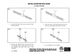
E. Securing the Rail to the Ceiling
Step 1. Remove the transformer power feed cap from the Step 4. While supporting the rail, screw the transformer
base of the power feed. (A) Power Feed Cap power feed cap back onto the transformer. The
connection must be tight.
Step 2. Remove the standoff caps. Step 5.Carefully screw the standoff caps back onto each of the
(B) Standoff Cap standoffs.
Step 3. Slide the rail into the standoffs and the transformer
power feed.
Page5-7
B
5
Slide the rail into the standoffs and the transformer
power feed.
e1.Remove the transformer power feed cap from the base
of the power feed.
E.Secure the rail to the Ceiling
Remove the standoff caps from each standoff. Screw the standoff caps back onto each of
the standoffs.
While supporting the rail,screw the transformer power
feed cap back onto the transformer.The connection
must be tight.

INSTALLATION INSTRUCTIONS
FOR P4305-084/P4305-467
WARNING! SHUT POWER OFF AT FUSE OR CIRCUIT BREAKER.
AVERTISSEMENT! COUPER LE COURANT AU NIVEAU DES FUSIBLES OU DU DISJONCTEUR.
F. Installation the fixtures
G. Restoring the Electrical Power
Step 1.
Locate the six fixtures with adjustable arm. Install LED fixture, led 3W MAX (Included)
(included)
Step 1. Restore the electrical power and proceed to test
your new rail system.
Step 2. Remove the fixture cap from each of the fixtures.
(A) Fixture Cap
Step 2. Turn on the light system and let it run for 5
minutes. Turn the system off, carefully check that all
connection points are not hot to the touch (warm is
acceptable), if a connection is hot, check the connection
and make sure the wire nut is tightly secured.
Step 3. Slide the fixture onto the rail and secure with a Power Feed Connection (A) Fixture Connections (B)
fixture cap.The connection must be tight and secure.
Repeat this step for the remaining fixtures.
NOTICE :
Fixture should be installed by a qualified electrician
to ensure proper wiring and installation.
Dimmer with C-L (CFL & LED) type
Brand : Lutron
Ordering Information ■Boxed ●Clamshell
Model number Product name Control Type Maximum Capacity
■Dvcl-153P- Diva C-L
Single-pole/ 3-way
dimmer
150w CFL/LED or 600w
incandescent/ Halogen
120v
●DVCl-153PH-
■ DVSCCL-153P Diva C-L Satin
Colors
■CTCL-153P- Skylark
Controur C-L
●CTCL-153PH-
■AYCL-153P-
Ariadni C-L
●AYCL-153PH-
●TTCL-100H- Credenza C-L Single-pole lamp
dimmer
100W CFL/ LED or
250W Incandescent/
Halogen 120v
Page6-7

INSTALLATION INSTRUCTIONS
FOR P4305-084/P4305-467
WARNING! SHUT POWER OFF AT FUSE OR CIRCUIT BREAKER.
AVERTISSEMENT! COUPER LE COURANT AU NIVEAU DES FUSIBLES OU DU DISJONCTEUR.
H. Important safety Instructions
CAUTION/ PRECAUCION : Do not touch hot lens, housing or enclosure when lit.
When installing or using this track system, basic safety precautions should always be followed
including the following:
a) Read all instructions
b) Do not conceal or extend conductors through a building wall
c) Do not install this system in damp and wet locations.
d) To reduce the risk of fire and burns, do not install this lighting system where the exposed bare
conductors can be shorted or contact any conductive materials.
e) To reduce the risk of fire and overheating, make sure all connections are tight.
f) Do not install any luminaire closer than 6 in (152mm) from any curtain, or similar combustible
materials.
g) Turn off electrical power before modifying the lighting system in any way.
h) Do not cut any track sections.
i) Do not install any part of a track system less than 5 feet above the floor.
j) Do not attempt to energize anything other than lighting track luminaires on the track. To reduce
the risk of fire and electric shock, do not attempt to connect power tools, extension cords, appliances,
and the like to the track.
SAVE THESE INSTRUCTIONS
Page7-7
/