AGFEO AS 33 Installation guide
- Category
- Serial switch boxes
- Type
- Installation guide
This manual is also suitable for

1
- Installation
Business-Line: AS 33
AS 34

2
Safety notes
ephones can be also connected to every
internal S0 bus.
Connected door hands free units must con-
form to the respective interface definition.
Any other use of the telephone system is
not in accordance with its intended purpose
and is therefore not permitted.
The telephone system has a general connec-
tion permit (Germany: AAE).
The telephone system is intended for con-
nection to an ISDN basic access (DSS 1). You
may connect all analog terminals to the ana-
log user ports of the telephone system that
you are also permitted to operate on the
analog telecommunications network.
You may connect all DSS 1 ISDN terminals
to an internal S0 bus that you are also al-
lowed to operate directly on the ISDN
network. Two digital AGFEO system tel-
Safety notes ¢¢¢¢¢¢¢¢¢¢¢¢¢¢¢¢¢¢¢¢¢¢¢¢¢¢¢¢¢¢¢¢¢¢¢¢¢¢¢¢¢¢¢¢¢¢¢¢¢¢¢¢¢¢¢¢¢¢¢¢¢
!
static charges, thus protecting
the telephone system's electro-
statically sensitive components.
- You must not connect and dis-
connect subscriber lines during
a thunderstorm.
- Lay subscriber lines in such a
way that no-one can step on
them or stumble over them.
- Prevent the ingress of liquid into
the telephone system as other-
wise short-circuits may occur.
- No liability can be assumed for
consequential damages such as
the cost of an unintentionally
continued connection.
- The telephone system is out of
operation whenever power fail-
ures occur. You cannot make
telephone calls in such cases.
- The telephone system conforms
to the prescribed conformity
and safety regulations.
- Attention! The telephone sys-
tem must be electrically
earthed. Therefore connect the
Euro PE contact plug of the
power cable only to an expertly
installed socket (PE socket) to
prevent danger to persons and
material.
- Before connecting the sub-
scriber lines to the subscribers
and the ISDN network, pull out
the 230 V mains plug to switch
off the telephone system. Mor-
tal danger!
- Protective measure! Touch the
metal shield of the PC/printer
socket of the telephone system
briefly with your finger.This will
discharge any possible electro-

3
Do not plug in the 230 V mains plug un-
til you have completed installation and
checked the wiring after closing the
housing.
Pay attention to the fact that the electri-
cal connection (shock-proof socket) for
the telephone system (and if applicable,
for additional devices) must have been
installed by an authorised electrician.
This will avoid any hazards for persons
and property.
Installation
Checking the scope of delivery ¢¢¢¢¢¢¢¢¢¢¢¢¢¢¢¢¢¢¢¢¢¢¢¢¢¢¢¢¢¢¢¢¢¢¢¢¢¢¢¢¢¢¢
- 1 Telephone system
- 1 Set of securing material (3 dowels S6,
3 wood screws (cross head recess)
4 x 40)
- 18 (14) connection terminals
- 2 (2) ISDN connecting cable (IAE-IAE),
1.5 m
- 1 ISDN connecting cable (IAE-single
wires)
- 1 PC connecting cable
- 1 Instruction package including instruction
manual, installation manual, short-form
operating instructions for system
telephones, short-form operating instruc-
tions for a/b and ISDN terminals, 8 remote
control cards
- 1 Set of 3.5" diskettes with the programs:
TK-Set, TK-LCR, TK-Bill, TK-Phone and TK-
Timer.
On our homepage "www.agfeo.de", you
may find the operating manuals for
download.
Choosing a location¢¢¢¢¢¢¢¢¢¢¢¢¢¢¢¢¢¢¢¢¢¢¢¢¢¢¢¢¢¢¢¢¢¢¢¢¢¢¢¢¢¢¢¢¢¢¢¢¢¢¢¢¢¢
- The telephone system must only be in-
stalled in a dry room in which there are
no explosion hazards.
It must not be installed: in the proximity
of air conditioning systems. Radiators, de-
vices that produce inadmissible interfer-
ence radiation, in locations that are sub-
ject to direct sunlight, in environments
containing excessive amounts of dust or
in locations where it may be splashed
with water or chemicals.
- Ambient temperature: 5°C to 40°C
- Humidity: max. 70% (no condensation)
- You must install the telephone system ver-
tically, with the connection side pointing
downwards, on a firm and flat surface.
- Minimum distance between the housing
and other limits above or below it: 50
mm.
- The distance between the telephone sys-
tem and the 230 V mains socket and the
IAE socket should not be more than 1 m
(mains lead approximately 1.2 m long).
- For configuration via the serial PC / printer
interface (RS 232C), it must be possible to
place a laptop or a PC in the direct prox-
imity of the telephone system.
A separate circuit is recommended for the
telephone system’s 230 V mains power sup-
ply.
Short-circuits caused by other domestic ap-
pliances will then not have any detrimental
influence on the telephone system.
Power consumption of the telephone sys-
tem: approximately 30 VA (full load).
230 V power supply ¢¢¢¢¢¢¢¢¢¢¢¢¢¢¢¢¢¢¢¢¢¢¢¢¢¢¢¢¢¢¢¢¢¢¢¢¢¢¢¢¢¢¢¢¢¢¢¢¢¢¢¢¢

4
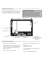
Opening the housing ¢¢¢¢¢¢¢¢¢¢¢¢¢¢¢¢¢¢¢¢¢¢¢¢¢¢¢¢¢¢¢¢¢¢¢¢¢¢¢¢¢¢¢¢¢¢¢¢¢¢¢¢
Press with a screwdriver onto the tabs in the
slits on the connection side of the housing.
The cover is released and you can detach it.
Securing the housing ¢¢¢¢¢¢¢¢¢¢¢¢¢¢¢¢¢¢¢¢¢¢¢¢¢¢¢¢¢¢¢¢¢¢¢¢¢¢¢¢¢¢¢¢¢¢¢¢¢¢¢¢
- Mark the mounting holes (M).
- When marking the mounting holes, make
sure that there are no concealed pipes or
cables at these points (gas, water and
power lines etc.).
- Drill the three mounting holes.
Stone drill: 6 mm, hole depth: 40 mm
or
Wood drill: 3.5 mm,
Hole depth: 35 mm
- Drive in the dowels until they are flush
with the wall.
- Screw in the telephone system.
Caution: mortal danger !
Before removing the inner cover, pull out
the 230 V mains plug to switch off the
telephone system. The inner cover may
only be removed by a service technician.
Drawing 1:
Open central housing
of the telephone
system
M: mounting
holes
Fuse, slow-blow
0,5 A / L 250 V
M
M
Cover latching
Cover
Cover latching
M
Securing web
System earth (BE)
Mains connection

5
Safety notes ¢¢¢¢¢¢¢¢¢¢¢¢¢¢¢¢¢¢¢¢¢¢¢¢¢¢¢¢¢¢¢¢¢¢¢¢¢¢¢¢¢¢¢¢¢¢¢¢¢¢¢¢¢¢¢¢¢¢¢¢¢
Pay attention to the safety notes
- before installing or removing a
module,
- before connecting or disconnecting
a connecting lead
1.Remove the telephone system's 230 V
mains plug from the socket.
2.Remove the Western plugs of all ex-
ternal ISDN basic accesses from the
telephone system, the network termi-
nator (NT) or the S0 bus.
3.Briefly touch the metal shield of the
PC/printer socket of the telephone
system with your finger. This will
discharge any possible electrostatic
charges, thus protecting the
telephone system’s electrostatically
sensitive components.
Connecting analog users ¢¢¢¢¢¢¢¢¢¢¢¢¢¢¢¢¢¢¢¢¢¢¢¢¢¢¢¢¢¢¢¢¢¢¢¢¢¢¢¢¢¢¢¢¢¢¢¢¢
You may connect all analog terminals to the
telephone system that you are also permit-
ted to operate on the analog telecommuni-
cations network.
a/b terminals are:
- Telephone (a/b telephone) with tone dial-
ling (DTMF).
r
key as the flash key (flash
time: 50-150 ms),
S
key and
R
key.
Only restricted use can be made of tel-
ephones that are set to pulse dialling.
- Group 3 fax machines
- Answering machines
- Modem V.90 standard (up to 56600 bps,
reduction possible by transmission path
and cables to 33600 bps V.34+).
Connect a/b terminals by means of two
wires to the La and Lb wires (speech wires)
of the Vario ports. You must not connect
the Da and Db connections.
System telephones ST 20
Connect system telephones ST 20 by four
wires to the Vario ports by connecting them
to the La and Lb wires (speech wires) and
the Da and Db wires (data wires; data for
signalling and displays).
For connection, carry out the following
work:
- Place the connecting leads through the
housing openings.
- Fit the screw terminals to the connecting
leads.
- Plug the screw terminals of the individual
leads onto the provided slots (see draw-
ings 2 and 3).
- If you route a connecting lead of the tel-
ephone system outside of the building,
you are advised to use external lightning
protection.
Connecting earth ¢¢¢¢¢¢¢¢¢¢¢¢¢¢¢¢¢¢¢¢¢¢¢¢¢¢¢¢¢¢¢¢¢¢¢¢¢¢¢¢¢¢¢¢¢¢¢¢¢¢¢¢¢¢¢¢
Connect the "Betriebserde BE" (system
earth) terminal to the equipotential bonding
connection of your household installation.
You must not connect the earth to the PE
conductor!
Earth: 1.5 mm+ stranded wire

6
GND
D-SUB-9 socket
S
0
-terminations
Door hands
free unit
Door
opener
2 Tx1
3 Rx1
5 GND
7 CTS1
8 RTS1
AR
TFE 1 (FTZ 123 D 12)
NF = DC-free speech circuit
AR = Terminals for potential-free bell button
TO = Door opener relay
TS = Relay for activating an external amplifier
TFE 1
FTZ123D12 TFE
Mustermann
Bell button
NF1
TO
TS
TFE 2
2-wire TFE
NF
U~
230 V
Bell transformer
for door opener
max. ~24 V
Door hands
free unit
Door
opener
Mustermann
Mustermann
Mustermann
Mustermann
Relays
max. contact load
30 VDC / 1 A
R11
R12
R21
R22
S
0
- 4
Internal only
a2
b2
a1
b1
S
0
- 3
external/
internal
S
0
- 2
External only
S
0
- 1
External only
RS 232C
Interface 2
Tx2
Rx2
RTS2
CTS2
GND
15
96
RS 232C
Interface 1
Wire pair 1 a1, b1
Wire pair 2 a2, b2
S
0
- 3
external
a1
b1
a2
b2
Western connector to the NTBA or
IAE socket.
a1: green
b1: brown
a2: yellow
b2: white
1 ... 8
3: a2
4: a1
5: b1
6: b2
S
0
- 3
internal
a2
b2
a1
b1
S100
S101
S201
S200
S300
S301
S302
S303
Switches S300,
S301, S302,
S303 closed!
At least
switches S302,
S303 open!
(see
illustration)
S100/S101 100 Ω termination
S
0
-1
S200/S201 100 Ω termination
S
0
-2
S300/S301 100 Ω termination
S
0
-3
S302/S303 Power supply for
S
0
-3
internal
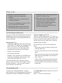
Drawing 2a:
Pin assignments of the bottom PC board AS 34

7
Systel 1
Db
Lb
4-wire
connection
1. Wire pair: La Lb
2. Wire pair: Da Db
System-
telephone
Da
La
a/b-
telephone
La
Lb
1
2
3
4
5
6
TAE 6 FN
La
Da
Lb
Db
Systel 2
Db
Lb
System-
telephone
Da
La
Tel 3
Systel
or a/b
Db
Lb
System-
telephone
Da
La
La
Lb
Tel 4
Systel
or a/b
Db
Lb
System-
telephone
Da
La
La
Lb
Tel 5
Systel
or a/b
Db
Lb
System-
telephone
Da
La
La
Lb
Tel 6
Systel
or a/b
Db
Lb
System-
telephone
Da
La
La
Lb
Tel 7
Systel
or a/b
Db
Lb
System-
telephone
Da
La
La
Lb
Tel 8
Systel
or a/b
Db
Lb
System-
telephone
Da
La
Tel 9
Tel 10
a/b
Lb
Lb
La
La
a/b-
telephone
a/b-
telephone
Tel 11
Tel 12
a/b
Lb
Lb
La
La
External MoH
GND
NF
40 V~
Additional bell
a/b-
telephone
a/b-
telephone
a/b-
telephone
a/b-
telephone
a/b-
telephone
a/b-
telephone
a/b-
telephone
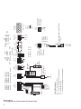
Drawing 2b:
Pin assignments of the top PC board AS 34
Pin assignments of a TAE socket
Da/Db only in the case of
system telephones!

8
GND
D-SUB-9 socket
S
0
-terminations
Door hands
free unit
Door
opener
2 Tx1
3 Rx1
5 GND
7 CTS1
8 RTS1
AR
TFE 1 (FTZ 123 D 12)
NF = DC-free speech circuit
AR = Terminals for potential-free bell button
TO = Door opener relay
TS = Relay for activating an external amplifier
TFE 1
FTZ123D12 TFE
Mustermann
Bell button
NF1
TO
TS
TFE 2
2-wire TFE
NF
U~
230 V
Bell transformer
for door opener
max. ~24 V
Door hands
free unit
Door
opener
Mustermann
Mustermann
Mustermann
Mustermann
Relays
max. contact load
30 VDC / 1A
R11
R12
R21
R22
S
0
- 4
Internal only
a2
b2
a1
b1
S
0
- 3
external/
internal
S
0
- 1
External only
RS 232C
Interface 2
Tx2
Rx2
RTS2
CTS2
GND
15
96
RS 232C
Interface 1
1. Wire pair a1, b1
2. Wire pair a2, b2
S
0
- 3
external
a1
b1
a2
b2
Western connector to the NTBA or
IAE socket.
a1: green
b1: brown
a2: yellow
b2: white
1 ... 8
3: a2
4: a1
5: b1
6: b2
S
0
- 3
internal
a2
b2
a1
b1
S100
S101
S300
S301
S302
S303
Switches S300,
S301, S302,
S303 closed!
At least
switches S302,
S303 open!
(see
illustration)
S100/S101 100 Ω termination
S
0
-1
S300/S301 100 Ω termination
S
0
-3
S302/S303 Power supply for
S
0
-3
internal
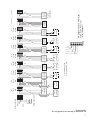
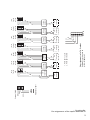
Drawing 3a:
Pin assignments of the bottom PC board AS 33

9
1. Wire pair: La Lb
2. Wire pair: Da Db
a/b-
telephone
La
Lb
1
2
3
4
5
6
TAE 6 FN
La
Da
Lb
Db
Tel 3
Systel
or /b
Db
Lb
System-
telephone
Da
La
La
Lb
Tel 4
Systel
or a/b
Db
Lb
System-
telephone
Da
La
La
Lb
Tel 5
Systel
or a/b
Db
Lb
Da
La
La
Lb
Tel 6
Systel
or a/b
Db
Lb
Da
La
La
Lb
Tel 7
Systel
or a/b
Db
Lb
Da
La
La
Lb
Tel 8
Systel
or a/b
Db
Lb
Da
La
Tel 9
Tel 10
a/b
Lb
Lb
La
La
External MoH
GND
NF
40 V~
Additional bell
a/b-
telephone
a/b-
telephone
a/b-
telephone
a/b-
telephone
a/b-
telephone
a/b-
telephone
a/b-
telephone
System-
telephone
System-
telephone
System-
telephone
System-
telephone
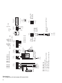
Drawing 3b:
Pin assignments of the top PC board AS 33
Pin assignments of a TAE socket
Da/Db only in the case of
system telephones!

10
External fixed S0 port (Western socket) ¢¢¢¢¢¢¢¢¢¢¢¢¢¢¢¢¢¢¢¢¢¢¢¢¢¢¢¢¢¢¢¢¢¢
Point-to-point connection
You can only connect one ISDN telephone
system to an ISDN point-to-point connec-
tion. You cannot connect any further ISDN
terminals.
By means of the ISDN connecting cable,
connect the ISDN system directly to the
NTBA or to an ISDN socket (IAE/UAE) that is
connected to the NTBA.
Terminators for the external S0 port
S0 port 1 - switches S100 and S101,
drawing 2a (3a)
S0 port 2 - switches S200 and S201,
drawing 2a
The two switches for the 100 Ohm termina-
tors, which must belong to one connecting
line, must be closed for the point-to-point
connection.
Point-to-multipoint connection
The point-to-multipoint connection may
consist of an S0 bus. Up to 12 ISDN sockets
(IAE/UAE) may belong to this ISDN bus. Be-
sides the ISDN telephone system, you can
connect up to seven further ISDN terminals
to the S0 bus.
Terminators for the external S0 port
S0 port 1 - switches S100 and S101,
drawing 2a (3a)
S0 port 2 - switches S200 and S201,
drawing 2a
For the point-to-multipoint connection, the
two switches for the 100 Ohm terminators,
which must belong to one S0 connecting
line, must be
- closed if the external S0 port is con-
nected directly to the NT or to the last
IAE/UAE socket and the 100 Ohm termi-
nators in the socket are not connected,
- open if the 100 Ohm terminators in the
last IAE/UAE socket are connected
or the telephone system is not the last
ISDN terminal on the point-to-multipoint
connection.
By means of the connecting cable, connect
the ISDN telephone system to an ISDN
socket of the S0 bus.
If the point-to-multipoint connection does
not consist of an S0 bus, you can connect
the ISDN telephone system directly to the
NT.

11
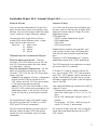
Switchable S0 port S0-3 / Internal S0 port S0-4 ¢¢¢¢¢¢¢¢¢¢¢¢¢¢¢¢¢¢¢¢¢¢¢¢¢¢¢
External S0 port
You can connect the external S0 port to a
point-to-point or a point-to-multipoint con-
nection. You will find notes under the head-
ing of "External S0 port (Western socket)".
Connect the four single wires of the in-
cluded ISDN cable (Western plug - single
wires) to the screw terminal:
Terminal a1 - green wire
b1 - brown
a2 - yellow
b2 - white
Terminations for the external S0 port
Point-to-point connection - The two
switches S130 /S02 (drawing 2a or 2b) for
the 100 Ohm terminators must be closed
("as-delivered" setting).
Point-to-multipoint connection - For the
point-to-multipoint connection, the two
switches S130 / S02 for the 100 Ohm termi-
nators must be:
- closed if the external S0 port is connected
directly to the NTBA or to the last IAE /
UAE socket and the 100 Ohm terminators
in the socket are not connected,
- open if the 100 Ohm terminators in the
last IAE / UAE socket are connected or the
telephone system is not the last ISDN ter-
minal on the point-to-multipoint connec-
tion.
For the external S0 port, the power supply
has to be switched off. To do this, switch
S302 and S303 must be opened.
Do not insert the Western plug of the con-
necting cable into your ISDN connection
socket until all installation work has been
completed.
Internal S0 port
As in the case of a point-to-multipoint con-
nection, you can connect up to eight ISDN
terminals to one internal S0 port 3 of the
telephone system.
ISDN terminals:
- AGFEO system telephones digital
- ISDN telephones
- ISDN cards
- ISDN fax machines
Depending on current consumption, you
may connect at least four ISDN terminals
that do not have a power supply of their
own.
Example: 4 ISDN telephones or 2 system
telephones digital and 2 ISDN telephones.
The ISDN terminals must operate in accord-
ance with the DSS1 protocol.
If S0 port 3 is used as second internal S0
bus, the switches S300, S301 (termination)
and S302, S303 (power supply) have to be
closed. Additionally, the port must not be
defined as external S0 port in the configura-
tion of the PBX.
You need the following material to install an
internal S0 port:
- Telecommunications cable; we recom-
mend the cable type I-Y (St) Y 2 x 2 x 0.6
long
- IAE or UAE connection sockets; up to 12
sockets
- Terminators, 100 Ohm, load carrying ca-
pacity 0.25 watt, 2 terminators
An internal S0 port may be 130 m long (dis-
tance from the telephone to the last IAE /
UAE socket)

12
100 Ω
Wire pair 1: a1, b1
Wire pair 2: a2, b2
b1
b2
a1
a2
S
0
- internal
100 Ω
Max. distance
130 m S
0
-bus
1
UAE
23456 78
1
UAE
2345678
1
UAE
2345678
1
UAE
234567 8
b1
b2
a1
a2
S
0
- internal
100 Ω 100 Ω
IAE
1a 1b 2a 2b
IAE
1a 1b 2a 2b
IAE
1a 1b 2a 2b
IAE
1a 1b 2a 2b
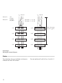
Notes¢¢¢¢¢¢¢¢¢¢¢¢¢¢¢¢¢¢¢¢¢¢¢¢¢¢¢¢¢¢¢¢¢¢¢¢¢¢¢¢¢¢¢¢¢¢¢¢¢¢¢¢¢¢¢¢¢¢¢¢¢¢¢¢¢¢¢¢
Pay attention during installation to the enu-
meration of the UAE sockets.
Do not confuse a2 with b2 or a1 with b1 !
Wire pair 1 red
b1 black
Wire pair 2 a2 white
b2 yellow
Drawing 4:
Wiring an internal S0 port

13
Connecting a door hands free unit (TFE) ¢¢¢¢¢¢¢¢¢¢¢¢¢¢¢¢¢¢¢¢¢¢¢¢¢¢¢¢¢¢¢¢¢
The telephone system features two inter-
faces for connecting door hands free units:
TFE 1 - interface conforming to the 4-wire
TFE specification FTZ 123 D12 for the con-
nection of door stations with amplifiers.
TFE 2 - interface conforming to the 2-wire
door hands free unit (CE interface) specifica-
tion.
TFE 1 - interface conforming to the 4-wire
TFE specification FTZ 123 D12
Connections: (drawings 2a, 3a)
- Connection of a potential-free bell
pushbutton to the contacts AR and GND.
The telephone system supports one bell
pushbutton.
- Connection of the DC-free speech circuit
of the TFE to a loudspeaker system or an
audio module AM 20 to the contacts NF1
and GND.
- Control of the TFE, of the loudspeaker
system (activation of the amplifier or
power supply) or of the audio module AM
20 (voice/music changeover) via the po-
tential-free relay contacts TS
Maximum contact load-carrying capacity:
30 VDC/1 A or 123 VAC/0.5 A.
- Control of the door opener via the poten-
tial-free relay contacts T0
Maximum contact load-carrying capacity:
30 VDC/1 A or 123 VAC/0.5 A.
You can only activate the door opener
from a terminal of the telephone system
after connecting an external bell trans-
former.
TFE 2 - interface conforming to the 2-wire
door hands free unit (CE interface) specifica-
tion.
The telephone system supports up to four
bell pushbuttons.
The dialling method is DTMF (dual tone
multifrequency).
Connections: (drawings 2a, 3a)
- Connection of the DoorLine T01 to T04
door hands free units to the contacts NF
and NF.
- Control of the door opener
Maximum contact load-carrying capacity:
30 VDC/1 A or 123 VAC/0.5 A.
You can only activate the door opener
from a terminal of the telephone system
after connecting an external bell trans-
former to the U~ terminals.
For connection, carry out the following op-
erations:
- Place the connecting leads through the
housing openings.
- Fit the screw terminals onto the connect-
ing leads.
- Insert the screw terminals of the individual
leads onto the provided slots (see draw-
ings 2a and 3a).
- If you route a connecting lead of the
telephone system outside of the building,
you are advised to use external lightning
protection.
Maximum contact load: 30 VDC/1 A or
125 VAC/0.5 A, ohmic load.

14
Switching relays ¢¢¢¢¢¢¢¢¢¢¢¢¢¢¢¢¢¢¢¢¢¢¢¢¢¢¢¢¢¢¢¢¢¢¢¢¢¢¢¢¢¢¢¢¢¢¢¢¢¢¢¢¢¢¢¢¢
You can put the relays to diverse use as indi-
vidual switching relays R1 and R2 with po-
tential-free contacts R11, R12 and R21, R22
for other functions. For example, you can
use them to connect an additional bell, a
door opener or lighting.
If not door hand free unit (FTZ 123 D12
standard) connected, also the relay contacts
T0 (relay R3) and TS (relay R4) may be used
for different functions.
By programming, for each relay you define
whether it is to operate as a pulse relay (3
seconds on) or as an On/Off relay.
You can switch the relays from every inter-
nal or external telephone. You can also as-
sign internal phone numbers to the relays in
order to include them in the ringing distribu-
tion settings, e.g. when connecting an addi-
tional bell.
The relay contacts are bridged with a 1
kOhm, 100 nF spark quenching combina-
tion.
To feed in external music on hold, connect
the headphone output of an audio device
(CD player, cassette recorder or stereo sys-
tem) to the "external MoH" (NF and GND)
terminal on the top pc board of the tel-
ephone system (drawings 2b, 3b or 5).
Set the volume of external music on hold on
the audio device. To set or check the vol-
ume, call an internal user of the telephone
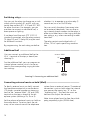
You can connect an additional bell to the
40 V ~ terminal of the top pc board (see
drawing 5).
For the additional bell, you can program an
internal phone number, which can be en-
tered in the corresponding ringing distribu-
tion settings.
Additional bell ¢¢¢¢¢¢¢¢¢¢¢¢¢¢¢¢¢¢¢¢¢¢¢¢¢¢¢¢¢¢¢¢¢¢¢¢¢¢¢¢¢¢¢¢¢¢¢¢¢¢¢¢¢¢¢¢¢¢
Connecting external music on hold (MoH) ¢¢¢¢¢¢¢¢¢¢¢¢¢¢¢¢¢¢¢¢¢¢¢¢¢¢¢¢¢¢¢¢
system from an external source. The external
connection is put on hold when the internal
user presses the inquiry key "R" or the
"brokering key". You hear the music on
hold and can adjust the volume.
Note: tunes played must be free from third-
party proprietary rights (GEMA-free).
external MoH
U~
GND
0~
NF
40 V~
Drawing 5: Connecting an additional bell

15
2
3
5
7
8
2
3
5
6
7
8
20
telephone system
(9-pole connector)
printer
(25-pole connector)
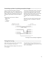
Connecting a printer for printing connection charges ¢¢¢¢¢¢¢¢¢¢¢¢¢¢¢¢¢¢¢¢¢
To print out connection records, the printer
must be on all the time and must be con-
nected to the telephone system. The tel-
ephone system stores at least 2000 connec-
tion records and the total connection
charges, even in the event of a power fail-
ure.
Remove the printer cable from the system
when no printer is connected. Close the
housing.
You can connect any printer to the tel-
ephone system’s RS 232C interface to print
out connection records. For connection, you
need a cable that corresponds to the pin as-
signments given below (maximum length 3
m).
Your printer must be set as follows:
- 9600 baud
- 8 bits
- 1 stop bit
- no parity
Drawing 6: Printer cable pin assignments
Closing the housing ¢¢¢¢¢¢¢¢¢¢¢¢¢¢¢¢¢¢¢¢¢¢¢¢¢¢¢¢¢¢¢¢¢¢¢¢¢¢¢¢¢¢¢¢¢¢¢¢¢¢¢¢¢
Hook the four top cover tabs into the cover
latch of the bottom housing half.
Press onto the bottom edge of the cover un-
til it engages.
The ventilation slots on the housing must
not be concealed. Make sure that air circula-
tion is not impeded.

16
Commissioning
You have installed the telephone system.
Now, only a few operations are necessary
before you are able to make telephone calls.
- Connect terminals. You can connect all
terminals that you are also allowed to
connect to the public telecommunications
network.
- Insert the Western plug on the ISDN con-
necting cable in the telecommunications
socket (ISDN line unit, IAE or universal line
unit UAE) of your ISDN connection.
- Switch on the telephone system by insert-
ing the mains plug.
- To avoid wrong dialling, dial a digit on an
a/b terminal with DTMF after installation.
The telephone system recognises the dial-
ling method in this way.
- If you switch the dialling method on an a/b
terminal from DTMF to pulse dialling, dial a
digit higher than 2.
- If you operate two terminals on one ter-
minal connection, both of them must dial
with the same dialling method.
Notes¢¢¢¢¢¢¢¢¢¢¢¢¢¢¢¢¢¢¢¢¢¢¢¢¢¢¢¢¢¢¢¢¢¢¢¢¢¢¢¢¢¢¢¢¢¢¢¢¢¢¢¢¢¢¢¢¢¢¢¢¢¢¢¢¢¢¢¢
- Once the telephone system has been
switched on, you can immediately make
internal and external telephone calls.
When an external subscriber calls, all con-
nected telephones ring according to the
telephone system's default settings ("as-
delivered" settings).
- By programming on a PC, you can set the
telephone system’s functions to suit your
needs. Remote setting by your specialist
dealer is possible.

17
As-delivered state
The followings settings are active in the as-
delivered state:
- The switches S100 /S101, S201/S202 (ter-
mination for the external S0 access) are
closed and the 100 Ohm terminators are
on.
- Switchable S0 access: the switches S302/
S303 are open (set to external), the
switches S300/S301 (termination for the
external S0 access) are closed and the 100
Ohm terminators are on.
- Internal phone numbers / terminal type:
telephone
AS 34: 11 (SysTel 1), 12 (SysTel 2), 13
(Tel 3) are called from externally
AS 33: 11 (SysTel 1), 12 (Tel 4), 13 (Tel 5)
are called from externally
- Outside line access: unlimited for all users
- Outside line seizure: "0"
- Call variant 1 (day time): no entry
- Call variant 2 (night time): no entry
- Internal call forwarding: off
- Do not disturb: off for all terminals
- Call waiting announcement prevention:
off for all terminals
- Phone number communication to the
called party and the caller: on
- Music on hold (MoH): internal on
- Automatic dialling: off
- Connection record printing: off for
all users
- Dialled phone number printing: none
- Cost limit: no entry
- Own tariff units factor: 0012
- Basic factor: 0.12
- Cleardown at cost limit: off
- Setup code: off
- Switching box code: no entry
- Busy tone on busy: off
- Communication of "0" for dialling from
the call list on the internal S0 access: off
System telephones ST 20 and ST 25
- Status display: off
- Cost display: off
- Display: German
- Call list: off
By programming on a PC, you can set the
telephone system’s functions to suit your
needs. Remote setting by your specialist
dealer is possible.

18
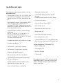
Technical data
Housing dimensions 32 x 25 x 8.5 cm (width x height x depth)
Ambient temperature
- Operation 5 ºC to 40 ºC
- Storage -25 ºC to +70 ºC
Mains connection 230 V AC, +6%/-10%, 50 Hz
- Power consumption 30 VA (full load)
External fixed S0 accesses Point-to-point or point-to-multipoint connection,
even mixed, ISDN (DSS1)
AS 34: 2 S0 accesses AS 33: 1 S0 access
Connection by means of Western sockets and
included IAE connecting cables IAE8/IAE8
Internal S0 accesses: Point-to-multipoint connection, ISDN (DSS1)
1 fixed S0 access,
1 switchable internal/external S0 access
(external: point-to-point or point-to-multipoint
connection)
4-pole plug-in connection by means of screw
terminals
Max. connection length 130 m
- ISDN terminals Max. 8 per internal S0 access, max. 4 passive ISDN
terminals (telephones) connected to the system
Analog terminals AS 34: 12 AS 33: 8
- Connection System telephones: 4-wire, plug-in screw terminal
a/b terminals: 2-wire, plug-in screw terminal
- Range System telephones 2 x 75 Ohm
(Ø 0.6 mm twisted, 1200 m)
a/b terminals: 2 x 50 Ohm (Ø 0.6 mm, 800 m)
- Dialling method Pulse dialling or DTMF
- Signal key Flash (80 + 30 ms)
PC/printer interface RS 232C
- Range 3 m
- Connection 9-pole, D-sub socket or plug-in screw terminal
Data retention in the event unlimited
of power failure:
External music on hold (MoH)
- Input impedance 100 kOhm, asymmetrical
- Input voltage Max. 100 mVpp
- Connection 2-pole, plug-in screw terminal
Door hands free unit TFE 1 in accordance with FTZ 123 D 12
- Connection 4-wire, plug-in screw terminal
- Contact load of the TS, TO relays 30 VDC/1 A or 125 VAC/0.5 A
Door hands free unit TFE 2 in accordance with CE
- Connection 2-wire, plug-in screw terminal
Switching relays R1, R2 - contact load 30 VDC/1 A or 125 VAC/0.5 A, ohmic load
Potential-free contacts jumpered with spark
quenching combination of 1 kOhm, 100 nF.
- Connection 2-wire, plug-in screw terminal

19
You can only use the numerous ISDN features of your AGFEO-ISDN telephone system if your
network operator has provided you with these features.
Copyright ¢¢¢¢¢¢¢¢¢¢¢¢¢¢¢¢¢¢¢¢¢¢¢¢¢¢¢¢¢¢¢¢¢¢¢¢¢¢¢¢¢¢¢¢¢¢¢¢¢¢¢¢¢¢¢¢¢¢¢¢¢¢¢
Copyright 1999 AGFEO GmbH & Co. KG
Gaswerkstr. 8
D-33647 Bielefeld
We reserve all rights for this documentation,
particularly in the event of patent granting
and utility model registration.
Neither the entire documentation nor parts
of if may be duplicated, transmitted, modi-
fied, stored in a database system nor trans-
lated to any language or computer language
in any form, manually or otherwise, using
any means whatever. This applies to elec-
tronic, mechanical, optical, chemical and
other media.
Trademarks and company names used in
this documentation are subject to the rights
of the respectively affected companies.
Technical modifications ¢¢¢¢¢¢¢¢¢¢¢¢¢¢¢¢¢¢¢¢¢¢¢¢¢¢¢¢¢¢¢¢¢¢¢¢¢¢¢¢¢¢¢¢¢¢¢¢¢¢
AGFEO GmbH & Co. KG reserves the right
to implement, without prior announcement,
modifications to depictions and information
in this documentation that serve the pur-
pose of technical progress.
This documentation was elaborated with
great care and attention and is revised on a
regular basis. Despite all checks, it is not
possible to rule out the fact that technical
inaccuracies and typographical errors may
have been overlooked. All errors known to
us are rectified in new editions. We are al-
ways grateful for information about errors in
this documentation.
Before calling your dealer you should have a
few data on hand for quicker service:
- What telephone system do you have?
- E.g. AGFEO AS 34 or AS 33 (on the type
plate of the system)
- What connection type (PTP and/or PTMP)
and which phone numbers do you have?
(is on the registration or confirmation of
the network operator)
- What software version do the AGFEO
installation diskettes have? (printed on the
diskettes)
- What software version does your
Technical Hotline ¢¢¢¢¢¢¢¢¢¢¢¢¢¢¢¢¢¢¢¢¢¢¢¢¢¢¢¢¢¢¢¢¢¢¢¢¢¢¢¢¢¢¢¢¢¢¢¢¢¢¢¢¢¢¢¢
telephone system have? (can be read out
on the PC or system telephone).
- What terminals have you connected to
your telephone system? (analog terminals
with and without DTMF dialing, ISDN
telephones, fax machines etc.)
- Keep the operating instructions of the
connected terminals and this manual at
the ready.
Start your PC and read out the configuration
with TK-Set. Print out the configuration of
your telephone system if possible.
If you have any questions regarding operation of your telephone system which these
operating instruction cannot answer, please contact your dealer.

20
This unit fulfills the requirements of the EU guidelines:
91/263/EWG Telecommunications equipment
73/23/EWG Low-voltage devices
89/336/EWG Electromagnetic compatibility
This is why your telephone system bears the CE mark.
AGFEO GmbH & Co. KG
Gaswerkstr. 8
D-33647 Bielefeld
Internet: http://www.agfeo.de
Ident. No. 529 354
Modifications and errors reserved.
Printed in Germany
1992
-
 1
1
-
 2
2
-
 3
3
-
 4
4
-
 5
5
-
 6
6
-
 7
7
-
 8
8
-
 9
9
-
 10
10
-
 11
11
-
 12
12
-
 13
13
-
 14
14
-
 15
15
-
 16
16
-
 17
17
-
 18
18
-
 19
19
-
 20
20


AGFEO AS 33 Installation guide
- Category
- Serial switch boxes
- Type
- Installation guide
- This manual is also suitable for
Ask a question and I''ll find the answer in the document
Finding information in a document is now easier with AI
Related papers
-
AGFEO AS 33 Installation guide
-
AGFEO AS 31 ST Installation guide
-
AGFEO AS 140 plus/AS 141 plus Installation guide
-
-
AGFEO AS 140/AS 141 Installation guide
-
-
AGFEO AS 40 Installation guide
-
-
-
Other documents
-
NAD Silver S300 User manual
-
McAfee NTBA T-200 Quick start guide
-
B-Speech Rx2 User manual
-
SICK S200 Safety Laser Scanner Operating instructions
-
Gira 1288 Series User manual
-
Bell -DDA User manual
-
Bell 801S User manual
-
e+p T 87/10 Datasheet
-
DETEWE EuroMaster Systel Operating Instructions Manual
-
Telegärtner UCT9 Operating instructions