Vertiv SL-70757_REVB_07-22_EN_Web.pdf User manual
- Type
- User manual

Model Design Configurations
Thank you for your recent purchase of a Vertiv Edge! We appreciate your
business and are confident that your new product will provide many years
of uninterruptible power to your connected equipment. With this purchase,
you may also want to consider Vertiv’s complete line of racks, PDUs, thermal
solutions, KVM switches, and serial consoles. Vertiv also oers a broad array
of services and extended warranties. If you require any assistance or support
please don’t hesitate to reach out to one of our resellers, local rep firms, or
directly to us at support.smallups.pdu@vertiv.com. We stand ready to sup-
port you. We sincerely hope that you’ll continue to select Vertiv for all of your
future infrastructure needs!
The Vertiv Team
I M P O R TA N T: Before installing,
connecting to supply or operating
your Vertiv™ Edge, please review the
Safety and Regulatory Statements
sheet. For detailed installation,
operating, maintenance and
troubleshooting information refer to
the Vertiv Edge User Guide your
model by scanning the QR code or
visiting www.Vertiv.com.
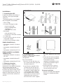
EDGELI-1500IRT2U EDGELI-2200IRT2U
Item Description Item Description
1Input Circuit Breaker 5Programmable Receptacles
(white)
2AC Input 6Non-programmable receptacles
3USB Communication Port 7Emergency Power O (EPO)
connector
4Vertiv™ Liebert® IntelliSlot™
Port 8Output Circuit Breakers
EDGELI-3000IRT2U
Vertiv™ Edge Lithium-Ion (LI) Series
230V 1,500VA - 3,000VA
Quick Installation Guide
SL-70757_REVB_07-22 1
Proprietary and Confidential ©2022 Vertiv Group Corp.

Installations
1. Inspecting the UPS
Inspect the contents of the box. If
anything is missing or damaged
contact us.
The following items are included in
the package for all the models:
• Vertiv™ Edge
• Accessory Package includes:
• Quick Install Guide
• Safety and Regulatory
Statements
• USB type A to B cable
• Rail kit box
• Left and right rail set
• 12 x Rail kit screws (M5 x 14mm)
• 4 x Tower feet
• 2 x UPS rack ears with 8 x rack ear
screws (M4 x 8mm)
• 2 x IEC C13 to C14 output cables
EDGELI-1500IRT2U only
• Input power cable IEC Schuko to
IEC C13
• Input power cable BS1362 to IEC
C13
• Input power cable AUS to IEC C13
EDGELI-2200IRT2U and EDGELI-
3000IRT2U only
• Input power cable IEC Schuko to
IEC C19
• Input power cable BS1362 to IEC
C19
• Input power cable AUS to IEC C19
2. Choosing a location
Install the Vertiv™ Edge in a
temperature controlled environment
that is free of corrosive and
conductive contaminants. Avoid
locations near heat or water sources
and exposed to direct sunlight. For
proper air flow, leave four inches of
clearance on the front and back of
the UPS.
3. Installing the UPS
The Vertiv™ Edge may be installed
in either a rack or tower
configuration.
For rack installation:
1. Attach a rack ear with four rack
ear screws to the front right and
left sides of the UPS.
2. Install the rear member of the
rail onto the rack with one rail
kit screw on the top and one on
the bottom. Loosely tighten the
screws (finger tight). Slide the
front member of the rail to the
front of the rack and secure the
two bottom holes to the rack
with two rail kit screws. Tighten
all screws. Repeat for the second
rail.
3. Place the UPS with assembled
rack ears onto the rail supports.
The batteries may be
temporarily removed for easier
installation (see Replacing the
Battery section)
4. Attach two rail kit screws to
each UPS rack ear and rail to
secure the UPS to the rack.
For tower installation:
1. Connect two tower feet together.
Repeat to assemble two tower
stands.
Rack Installation
Tower Installation
70 mm 70 mm
1 2
43
2 SL-70757_REVB_07-22
Vertiv™ Edge Lithium-Ion (LI) Series 230V 1,500VA - 3,000VA
Quick Installation Guide
Proprietary and Confidential ©2022 Vertiv Group Corp.

2. Place the UPS in the tower stands
70 mm from each edge of the
UPS.
Connections
4. Connecting Loads
The UPS has non-programmable and
programmable rear outlets. Plug
your critical equipment (such as
computer, monitors, etc.) into the
non-programmable outlets and your
less critical equipment (less often
used peripherals) into the
programmable outlets. Do not plug
in the UPS input power until after all
load and optional connections have
been made.
5. Network communication card
connection (optional)
Advanced monitoring and simple
control of the Vertiv™ Edge can be
done with the use of a Vertiv™
Liebert® IntelliSlot™
Communications card. Visit www.
Vertiv.com/IntelliSlot for additional
information
1. Remove the two screws and
protective cover on the rear panel
network communications port.
2. Insert the card into the port and
secure it with the screws. Refer to
the documentation with the card
or at the link above for cable
connection and operation.
6. USB Communication
Connection (Optional)
Basic monitoring of the Vertiv™ Edge
and unattended controlled shutdown
of your computer in case of a power
failure can be done using the Vertiv™
Power Assist software via the USB
port. Visit www.Vertiv.com/PowerAssist
for additional information.
7. Emergency Power O (EPO)
Connection (Optional)
To comply with national and local
wiring codes and regulations, the
EPO connector internally
disconnects all power sources to
connected equipment. To use this
feature remove the factory
installed jumper on the rear panel
EPO connector and connect to
active-open contacts that are
normally closed but open during
an emergency power o event.
Operating logic may be reversed
in the settings menu. If you do not
use the EPO connector, leave the
factory installed jumper in place
and the default (active open) EPO
setting in the settings menu.
8. Connecting AC Input
Ensure that all the loads are first
powered o. Connect to an input
power supply/wall outlet that is
properly protected by a circuit
breaker in accordance with
national and local electrical codes.
The input receptacle must be
grounded. Once the UPS is
plugged into the wall outlet, it
begins charging the battery.
Operation
9. Starting up the UPS
Plug the UPS input plug into a
stable 230VAC source. The LCD
display turns on and the batteries
begin charging. Press and hold the
ENTER/ button for two seconds
until the output turns on. The UPS
is in Battery Self Test mode for 10
seconds. After a successful
battery self test, the UPS is in On
Mode.
10. Shutting down the UPS
Press and hold the ENTER/ button
for two seconds and use the popup
window to confirm that the UPS
should be turned o. This will turn
the outlets o. Disconnect the input
power.
11. Fully shutting down
the UPS
After turning the UPS o, remove
input power, then remove the front
bezel and disconnect the battery
connector. Replace the front bezel.
The unit is now fully shut down.
Maintenance And Battery
Replacement
Precaution
Although the Vertiv™ Edge is
designed and manufactured to
ensure personal safety, improper use
can result in electrical shock or fire.
To ensure safety, observe the
following precautions:
• Turn o and unplug the UPS before
cleaning it.
• Clean the UPS with a dry cloth. Do
not use liquid or aerosol cleaners.
• Never block or insert any objects
into the UPS ventilation holes or
openings.
• Do not place the UPS power cord
where it might be damaged.
Battery Charging
The batteries are lithium ion and
should be kept charged to attain
their design life. The Vertiv™ Edge
charges the batteries continuously
when it is connected to the utility
input power. If the Vertiv™ Edge will
be stored for a long time, we
recommend connecting the UPS to
input power for at least three hours
every four to six months to ensure
full recharge of the batteries.
SL-70757_REVB_07-22 3
Vertiv™ Edge Lithium-Ion (LI) Series 230V 1,500VA - 3,000VA
Quick Installation Guide
Proprietary and Confidential ©2022 Vertiv Group Corp.

Replacing the Battery
I M P O R TA N T: Before you proceed,
please review the battery safety
precautions available at https://www.
vertiv.com/
ComplianceRegulatoryInfo.
You may safely replace the internal
battery pack. See the Specifications
in the User Guide online at www.
Vertiv.com for the part number of the
replacement battery for your UPS
model number.
NOTE: Replace the battery with the
same type and number asoriginally
installed.
12. Removing the front panel
Remove the front bezel by pulling
firmly until the snaps release. The
Vertiv™ Edge battery can be hot
swapped and may be replaced while
the UPS is on and plugged in. As
long as the utility power is available,
power to the outlets will remain.
13. Disconnecting the battery
wires
Disconnect the battery connector
by squeezing the ends and pulling
apart.
14. Removing the battery box
Remove the four screws and the
metal battery cover. Pull the battery
kit out.
Vertiv™ Edge Battery Replacement
15. Installing the new battery
Orient the connector and the new
battery in the same way as the
original battery, then slide them into
the UPS. Reinstall the metal battery
cover.
16. Reconnecting the battery and
front panel
Reconnect the battery connectors.
Snap the front bezel back on.
17. Resetting battery statistics
Navigate through the menu to
Settings > Battery > Replace Battery and
confirm battery replacement.
NOTE: Default password is 111111.
18. Disposing of the old battery
Properly dispose of old batteries at
an appropriate recycling center or
return them to Vertiv in the packing
material for the replacement
batteries.
4 SL-70757_REVB_07-22
To contact Vertiv Technical Support: visit www.Vertiv.com
©2022 Vertiv Group Corp. All rights reserved. Vertiv™ and the Vertiv logo are trademarks or registered trademarks of Vertiv Group Corp. All other names and logos referred to are trade
names, trademarks or registered trademarks of their respective owners. While every precaution has been taken to ensure accuracy and completeness here, Vertiv Group Corp. assumes no
responsibility, and disclaims all liability, for damages resulting from use of this information or for any errors or omissions. Specifications, rebates and other promotional oers are subject to
change at Vertiv’s sole discretion upon notice.
Vertiv™ Edge Lithium-Ion (LI) Series 230V 1,500VA - 3,000VA
Quick Installation Guide
-
 1
1
-
 2
2
-
 3
3
-
 4
4


Vertiv SL-70757_REVB_07-22_EN_Web.pdf User manual
- Type
- User manual
Ask a question and I''ll find the answer in the document
Finding information in a document is now easier with AI
Related papers
-
Vertiv Liebert GXT5 Lithium-Ion 1-3kVA User manual
-
-
-
-
-
-
-
-
-