Page is loading ...

Performance Motion Devices, Inc.
1 Technology Park Drive
Westford, MA 01886
Revision 1.3, April 2021
Magellan
®
Motion Control IC
DK58113 Developer Kit User Manual

ii DK58113 Developer Kit User Manual
NOTICE
This document contains proprietary and confidential information of Performance Motion Devices, Inc., and is pro-
tected by federal copyright law. The contents of this document may not be disclosed to third parties, translated, copied,
or duplicated in any form, in whole or in part, without the express written permission of PMD.
The information contained in this document is subject to change without notice. No part of this document may be
reproduced or transmitted in any form, by any means, electronic or mechanical, for any purpose, without the express
written permission of PMD.
Copyright 1998–2021 by Performance Motion Devices, Inc.
Juno, Atlas, Magellan, ION, Prodigy, Pro-Motion, C-Motion and VB-Motion are trademarks of Performance Motion
Devices, Inc.

DK58113 Developer Kit User Manual iii
Warranty
Performance Motion Devices, Inc. warrants that its products shall substantially comply with the specifications
applicable at the time of sale, provided that this warranty does not extend to any use of any Performance Motion
Devices, Inc. product in an Unauthorized Application (as defined below). Except as specifically provided in this
paragraph, each Performance Motion Devices, Inc. product is provided “as is” and without warranty of any type,
including without limitation implied warranties of merchantability and fitness for any particular purpose.
Performance Motion Devices, Inc. reserves the right to modify its products, and to discontinue any product or service,
without notice and advises customers to obtain the latest version of relevant information (including without limitation
product specifications) before placing orders to verify the performance capabilities of the products being purchased.
All products are sold subject to the terms and conditions of sale supplied at the time of order acknowledgment,
including those pertaining to warranty, patent infringement and limitation of liability.
Unauthorized Applications
Performance Motion Devices, Inc. products are not designed, approved or warranted for use in any application where
failure of the Performance Motion Devices, Inc. product could result in death, personal injury or significant property
or environmental damage (each, an “Unauthorized Application”). By way of example and not limitation, a life support
system, an aircraft control system and a motor vehicle control system would all be considered “Unauthorized
Applications” and use of a Performance Motion Devices, Inc. product in such a system would not be warranted or
approved by Performance Motion Devices, Inc.
By using any Performance Motion Devices, Inc. product in connection with an Unauthorized Application, the
customer agrees to defend, indemnify and hold harmless Performance Motion Devices, Inc., its officers, directors,
employees and agents, from and against any and all claims, losses, liabilities, damages, costs and expenses, including
without limitation reasonable attorneys’ fees, (collectively, “Damages”) arising out of or relating to such use, including
without limitation any Damages arising out of the failure of the Performance Motion Devices, Inc. product to
conform to specifications.
In order to minimize risks associated with the customer’s applications, adequate design and operating safeguards must
be provided by the customer to minimize inherent procedural hazards.
Disclaimer
Performance Motion Devices, Inc. assumes no liability for applications assistance or customer product design.
Performance Motion Devices, Inc. does not warrant or represent that any license, either express or implied, is granted
under any patent right, copyright, mask work right, or other intellectual property right of Performance Motion
Devices, Inc. covering or relating to any combination, machine, or process in which such products or services might
be or are used. Performance Motion Devices, Inc.’s publication of information regarding any third party’s products or
services does not constitute Performance Motion Devices, Inc.’s approval, warranty or endorsement thereof.
Patents
Performance Motion Devices, Inc. may have patents or pending patent applications, trademarks, copyrights, or other
intellectual property rights that relate to the presented subject matter. The furnishing of documents and other materials
and information does not provide any license, express or implied, by estoppel or otherwise, to any such patents,
trademarks, copyrights, or other intellectual property rights.
Patents and/or pending patent applications of Performance Motion Devices, Inc. are listed at
https://www.pmdcorp.com/company/patents.

iv DK58113 Developer Kit User Manual
Related Documents
Magellan
®
Motion Control IC User Guide
Complete description of the Magellan Motion Control IC features and functions with detailed theory of its
operation.
MC58113 Electrical Specifications
Information on physical and electrical characteristics, timing diagrams, pin descriptions, application notes
and application schematics of MC58113 IC.
Magellan
®
Motion Control IC Programming Reference
Descriptions of all Magellan Motion Control IC commands, with coding syntax and examples, listed alpha-
betically for quick reference.
PMD Resource Access Protocol Programming Reference
Description of all Prodigy/CME and ION/CME product commands with software architecture overview,
command syntax, and examples.
Atlas Digital Amplifier User Manual
Description of the Atlas Digital Amplifier electrical and mechanical specifications along with a summary of
its operational features.
Atlas Digital Amplifier Complete Technical Reference
Complete technical and mechanical description of the Atlas Digital Amplifier with detailed theory of
operations.

DK58113 Developer Kit User Manual v
1
Table of Contents
1. Installation .................................................................................................. 7
1.1 Introduction ........................................................................................................................................ 7
1.2 Magellan Motion Control IC Family Overview ........................................................................ 8
1.3 Developer Kit Components List ................................................................................................... 9
1.4 DK58113 Board................................................................................................................................... 9
1.5 Included Accessories..................................................................................................................... 10
1.6 Installation Overview .................................................................................................................... 10
1.7 Recommended Hardware ........................................................................................................... 10
1.8 Software Installation ..................................................................................................................... 11
1.9 Preparing the Board for Installation ........................................................................................ 13
1.10 Connection Summary ................................................................................................................ 14
1.11 Applying Power ............................................................................................................................ 17
1.12 First-Time System Verification................................................................................................. 18
2. Operation ................................................................................................. 23
2.1 DK58113 Block Diagram .............................................................................................................. 23
2.2 Communication Ports................................................................................................................... 24
2.3 Switching Motor Amplifier.......................................................................................................... 26
2.4 Drive Protection and Control Signals...................................................................................... 30
2.5 DC Bus ................................................................................................................................................ 32
2.6 Connecting to a Remote Amplifier .......................................................................................... 34
2.7 Connecting to an Atlas Amplifier ............................................................................................. 35
2.8 Motor Feedback Signals............................................................................................................... 35
2.9 Enable and FaultOut Signals ...................................................................................................... 38
2.10 Multi-board Synchronization................................................................................................... 39
2.11 On-IC NVRAM Configuration Storage................................................................................... 40
3. Electrical Reference ................................................................................. 41
3.1 User-Settable Components ........................................................................................................ 41
3.2 Connectors........................................................................................................................................ 42
3.3 Motor Connection Quick Reference ........................................................................................ 49
3.4 Absolute Maximum Ratings ....................................................................................................... 49
3.5 Environmental and Electrical Ratings ..................................................................................... 50
3.6 DK58113 On-Board Amplifier Quick Reference................................................................... 50

vi DK58113 Developer Kit User Manual
This page intentionally left blank.

DK58113 Developer Kit User Manual 7
1
1.Installation
In This Chapter
Introduction
Magellan Motion Control IC Family Overview
Developer Kit Components List
DK58113 Board
Included Accessories
Installation Overview
Recommended Hardware
Software Installation
Preparing the Board for Installation
Connection Summary
Applying Power
First-Time System Verification
1.1 Introduction
The PMD DK58113 Developer Kit is an integrated board/software package that serves as an electrical and software
design tool for building systems that use Magellan MC58113-series ICs.
The developer kits support all members of the MC58113 IC family, as shown below:
All of the above Developer Kit versions share the same physical DK58113 board. They differ in the specific type of
MC58113-series IC chip that is installed in the board.
Note that throughout this manual the term MC58113 may be used to mean all members of the MC58113 series including
the MC58113, MC53113, MC51113, and MC54113 ICs. The term DK58113 may be used to mean to all members of
the DKs including the DK58113, DK53113, DK51113, and DK54113 developer kits.
Developer Kit
p/n Installed IC Motors supported Comments
DK58113 MC58113 DC Brush, Brushless DC, step motor
DK58113S MC58113S DC Brush, Brushless DC, step motor Socketed version of DK58113
DK53113 MC53113 Brushless DC
DK51113 MC51113 DC Brush
DK54113 MC54113 Step motor

Installation
8DK58113 Developer Kit User Manual
1
1.2 Magellan Motion Control IC Family
Overview
The following table presents a feature summary of the products in the Magellan Motion Control IC product family:
MC58000 Series
(Except MC58113)
MC55000 Series MC58113 Series
# of axes 1, 2, 3, 4 1, 2, 3, 4 1+ (primary & aux
channel encoder input)
Motor types supported DC brush, brushless DC,
step motor
Step motor DC brush, brushless DC,
step motor
Output format SPI Atlas, PWM, DAC,
Pulse & direction
Pulse & direction SPI Atlas, PWM, DAC,
Pulse & direction
Parallel host communication
Serial host communication
CAN 2.0B host communication
SPI host communication
Incremental encoder input
Parallel word device input
Index & Home signals
Position capture
Directional limit switches
PWM output
Parallel DAC output
SPI Atlas interface
SPI DAC output
Pulse & direction output
Digital current control (with Atlas)
Field oriented control (with Atlas)
Under/overvoltage sense (with Atlas)
1
2
T Current foldback (with Atlas)
DC Bus shunt resistor control
Overtemperature sense (with Atlas)
Short circuit sense (with Atlas)
Ground fault detection (with Atlas)
Trapezoidal profiling
Velocity profiling
S-curve profiling
Electronic gearing
On-the-fly changes
PID position servo loop
Dual biquad filters
Dual encoder loop (multi-axis
configurations only)
Programmable derivative sampling
time
Feedforward (accel & vel)
Data trace/diagnostics
Motion error detection (with encoder)
Axis settled indicator (with encoder)
Analog input
Programmable bit output
Software-invertible signals
User-defined I/O
Internal Trace Buffer
External RAM support
Multi-chip synchronization

Installation
DK58113 Developer Kit User Manual 9
1
1.3 Developer Kit Components List
The DK58113 Developer Kit contains the following components:
• DK58113 Developer Kit board
• Cable set and pin breakout mini-cards for various card connectors
• Magellan SDK containing C-Motion and documentation in PDF format
• Pro-Motion Windows-based exercisor
If any of these components are missing, please contact your PMD representative.
1.4 DK58113 Board
The heart of the DK58113 Developer Kit is the DK58113 printed circuit board that contains interface and amplifier
circuitry to allow various features of the MC58113-family ICs to be accessed. Here is a summary of the features
provided by the DK58113 board:
• Supports step, DC Brush, and Brushless DC motors
• Socketed version of DK (DK58113S) allows MC58113s to be swapped out for testing or user
configuration storage
• High performance on-card amplifier with current feedback supports all motor types
• Interfaces to external Atlas, user-designed, or pulse & direction amplifier
• RS-232, RS-485, CANbus, and SPI (Serial Peripheral Interface) host communications
• Single DC-voltage supply
• Primary and auxiliary axis quadrature signal input with Index and Home capture
• Hall sensor, Home, limits, AxisIn and AxisOut signals
• Support for overtemperature, overcurrent, over and undervoltage sense
• High current external shunt resistor support
• Pulse & Direction signals with AtRest for use with external step motor amplifiers
Chipset configurations MC58420 (4 axes, 2 ICs)
MC58320 (3 axes, 2 ICs)
MC58220 (2 axes, 2 ICs)
MC58120 (1 axis, 2 ICs)
MC58110 (1 axis, 1 IC)
MC55420 (4 axes, 2 ICs)
MC55320 (3 axes, 2 ICs)
MC55220 (2 axes, 2 ICs)
MC55120 (1 axis, 2 ICs)
MC55110 (1 axis, 1 IC)
MC51113 (1+ axis, 1 IC)
MC53113 (1+ axis, 1 IC)
MC54113 (1+ axis, 1 IC)
MC58113 (1+ axis, 1 IC)
IC Package: CP chip MC58x20: 144 pin TQFP
MC58110: 144 pin TQFP
MC55x20: 144 pin TQFP
MC55110: 144 pin TQFP
100 pin TQFP
IC Package: IO chip MC58x20: 100 pin TQFP
MC58110: NA
MC55x20: 100 pin TQFP
MC55110: NA
N/A
Motion control IC
developer kit p/n’s
DK58420
DK58320
DK58220
DK58120
DK58110
DK55420
DK55320
DK55220
DK55120
DK55110
DK51113
DK53113
DK54113
DK58113
DK58113S
MC58000 Series
(Except MC58113)
MC55000 Series MC58113 Series

Installation
10 DK58113 Developer Kit User Manual
1
• Compact 3.3" x 4.7" standalone form factor (8.4 cm x 11.9 cm)
1.5 Included Accessories
The DK58113 includes various accessories that you may find useful:
If for whatever reason you need to order more of these accessories, refer to the part numbers above and contact your
PMD representative.
1.6 Installation Overview
1Before using the DK board, the software must be installed. See Section1.8, “Software Installation” for
instructions on installing the software.
2For a normal installation of the DK58113 board you will need to configure the board. See Section1.9,
“Preparing the Board for Installation” for a description of configuring the board.
3Next, connect the system’s motors, encoder(s), and sensors to operate the motion hardware. See
Section1.10, “Connection Summary” for a description of the available connections and options for the
DK58113 board.
4Connect the DK58113 board to the host PC via a Serial cable. This is described in Section1.10.4,
“Communication Connections.”
5Once this hardware configuration is complete, the final step to finish the installation is to perform a
functional test of the finished system. See Section1.12, “First-Time System Verification” for a
description of this procedure.
Once these steps have been accomplished, the installation is complete, and the board is ready for operation.
1.7 Recommended Hardware
To install a DK58113 board the following hardware is recommended. Note that this list assumes that the on-card
amplifier will be used. For installation of a user-provided off-card amplifier, see Section2.6, “Connecting to a Remote
Amplifier.”
Component PMD Part
Number
Description
Cable-USB-DB9 USB to 9-pin serial cable. This cable connects to the DK58113’s DB-9
serial port and to the PC's USB port.
Cable-4705-KIT-01.R CANbus connector and terminator. This cable connects to the card’s
CANbus connector and has RJ45 connectors on both ends.
MC-HW-05 DB-15 breakout interconnect. This module provides convenient jack-screw
type terminators for the 15-pin axis connectors. Two units included.
CONN-0122-11 Power & shunt connector jack screw terminals. This two-pin plug provides
convenient jack-screw-type terminals for the high current terminal block
header power & shunt resistor connectors. Two units included
CONN-0121-11 Motor connector jackscrew terminals. This five-pin plug provides convenient
jack-screw-type terminals for the high current terminal block header motor
connector.


Installation
12 DK58113 Developer Kit User Manual
1
1.8.1 Pro-Motion
Pro-Motion is a sophisticated, easy-to-use exerciser program which allows all Magellan IC parameters to be set and/
or viewed, and allows all features to be exercised. Pro-Motion features include:
• Motion oscilloscope graphically displays processor parameters in real-time
• AxisWizard to automate axis setup and configuration
• Position loop and current loop auto-tuning
• Project window for accessing motion resources and connections
• Ability to save and load settings
• Distance, time, and electrical units conversion
• Frequency sweep and bode plot analysis tools
• Motor-specific parameter setup
• Axis shuttle performs continuous back and forth motion between two positions
• C-Motion Engine monitor debug window
• C-Motion Engine user application code download
1.8.2 C-Motion
C-Motion provides a convenient set of callable routines comprising the C language code required for controlling
Magellan ICs. C-Motion includes the following features:
• Magellan axis virtualization
• Ability to communicate to multiple PMD motion cards or modules
• Ability to communicate via PC/104 bus, serial, CANbus, Ethernet, SPI (Serial Peripheral Interface), or
8/16 bit parallel bus
• Provided as source code, allowing easy compilation & porting onto various run-time environments
including a PC, microprocessor, embedded card, or C-Motion Engine
• Can be easily linked to any C/C++ application
C-Motion is described in the Magellan Motion Control IC Programming Reference.
1.8.3 .NET Language Support
A complete set of methods and properties is provided for developing applications in Visual Basic and C# using a
dynamically loaded library (DLL) containing PMD library software. The DLL may also be used from any language
capable of calling C language DLL procedures, such as Labview, but no special software support is provided.
Includes the following features:
• Magellan axis virtualization
• Ability to communicate to multiple PMD motion cards or modules
• Ability to communicate via PC/104 bus, serial, CANbus, or Ethernet
• Provided as a single DLL and Visual Basic .NET source code for easy porting onto various PC
environments

Installation
DK58113 Developer Kit User Manual 13
1
VB Motion is documented in the PMD Resource Access Protocol Programming Reference.
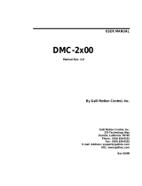
1.9 Preparing the Board for Installation
Figure 1-1 shows the location of various on-card components such as connectors and jumpers.
Figure 1-1:
DK58113
Board
Components
Location
The following table describes these components:
There are no jumper changes that need to be made to the board. The DK58113 comes factory-configured to be
compatible with the ‘first time installation’ instructions contained in this chapter.
Label Description
J1 HV Power Connector
J3 Motor Drive Connector
J8 Axis 1 Feedback Connector
J9 Axis 2 Feedback Connector (auxiliary axis)
J4 Amplifier Signal Connector
J10 SPI Atlas Bus Connector
J12 Remote Amplifier Connector
J14 Shunt Connector
J6, J7 CAN1, CAN2 Connectors (respectively)
J5 Serial Connector
J11 Host SPI Connector
J13 Synch Connector
J2 +5V Power Connector
D1, D2, D3 Power, fault, and amplifier enabled LED indicators
(respectively)
JP1, JP2 Remote amplifier enable jumpers
JP4 RS-232/RS-485 selector jumper
CAN2
J7
CAN1
J6
CAN
Connectors
J1
J3
HV
Power
Connector
Motor Drive
Connector
J14
Shunt
Connector
J5
Serial
Connector
J11
Host SPI
Connector
J13
Synch
Connector
J10
SPI Atlas
Bus
Connector
Axis 1
Feedback
Connector
Axis 2
Feedback
Connector
J2
+5V Power
Connector
J12
Remote
Amplifier
Connector
JP1 JP2
Remote Amplifier
Enable Jumpers
D1 D2
D3
J4
Amplifier
Signal
Connector
JP4 RS-232/RS485
Selector
Jumper
Amplifier
Enabled
Indicator
Power
Indicator
Fault
Indicator
J9
J8
MC58113

Installation
14 DK58113 Developer Kit User Manual
1
However, for reference the table below shows the available jumper settings of the DK58113 board:
1.9.1 Enabling the Board
The MC58113 requires an active Enable signal to operate. To accomplish this the Amplifier Signal Connector (J4) is
used. Connect terminal #1 of J4 to terminal #3 of J4 using a short wire. J4 provides convenient push-type
connections, so no other hardware is needed to make this connection.
For reference the following table provides the pinouts of the J4 terminal block connector:
1.10 Connection Summary
Figure 1-2:
Brushless DC
Motor
Connection
Overview
Jumper ID
Factory Default
Setting Setting &Description
JP1, JP2 1-2 (on-card amplifier) 1-2 Installing jumpers at 1-2 for JP1 and JP2 configures the
DK58113 for operation of the on-card amplifier.
2-3 Installing jumpers at 2-3 for JP1 and JP2 disables the on-
board amplifier, and configures the DK58113 for
operation with a user-designed amplifier via the J12
Remote Amplifier Connector, or with an Atlas DK
amplifier via the J10 connector.
JP4 1-2 (RS-232) 1-2 Installing a jumper at 1-2 for JP4 configures the DK58113
for RS-232 serial operation.
2-3 Installing a jumper at 2-3 for JP4 configures the DK58113
for RS-485 serial operation.
Setting & Description Pin # Description
Enable 1 Enable input. Must be tied low (GND) to enable
the MC58113 for full operation.
FaultOut 2 Programmable FaultOut signal output.
GND 3 Digital ground
Motor A
Motor B
Motor C
Hall Sensor Feedback
Brushless
DC
Amplifier
3 - Phase
Brushless
DC Motor
MC58113
or
MC53113
Serial
CANbus
SPI
Host I/O
Home, limits, and Encoder Feedback
Axis 1
Feedback
Connector
Motor
Drive
Connector
HV GND
Amplifier
Signal Connector
Enable
HV Power
Connector

Installation
DK58113 Developer Kit User Manual 15
1
Figure 1-3:
DC Brush
Motor
Connection
Overview
Figure 1-4:
Step Motor
Connection
Overview
Figures 1-2 through 1-4 provide general connection overviews for Brushless DC, DC Brush, and step motors.
You will need to connect signals on various connectors to properly install the DK58113 board with the attached
motor. The following three sections detail how this should be done.
1.10.1 Axis Feedback Connections
The following table summarizes the Axis signal connections to the DK58113. All connections are made through the
Axis Feedback Connector for axis #1 (J8), which is a high density female DB-15.
Home, limits, and Encoder Feedback Axis 1
Feedback
Connector
DC
Brush
Amplifier
DC Brush
Motor
MC58113
or
MC51113
Motor
Drive
Connector
Amplifier
Signal Connector
Enable HV GND
HV Power
Connector
Motor A
Motor B
Serial
CANbus
SPI
Host I/O
Pin # Signal Name Description
1 QuadA1+ Differential A+ quadrature input. optional for step motor axes
2 QuadA1- Differential A- quadrature input. optional for step motor axes
3 QuadB1+ Differential B+ quadrature input. optional for step motor axes
4 QuadB1- Differential B- quadrature input. optional for step motor axes
5 GND This is the preferred ground connection for the quadrature and Index signal inputs
6 Index1+ Differential Index+ quadrature input. optional for step motor axes
Home, Limits, and Optional Encoder Feedback
Step Motor
Amplifier
2 - Phase
Step
Motor
MC58113
or
MC54113
Axis 1
Feedback
Connector
Motor
Drive
Connector
Motor Power
Connector
Motor C
Motor D
Motor A
Motor B
HV GND
Amplifier
Signal Connector
Enable
Serial
CANbus
SPI
Host I/O

Installation
16 DK58113 Developer Kit User Manual
1
1.10.1.1 Single-ended Encoder Connections
Encoder inputs may be connected differentially, with two wires per signal (as shown in the table above), or with just
one wire per signal. If single-ended encoders are used, connect encoder signals to the positive encoder input only. The
negative input may remain unconnected.
1.10.1.2 Auxiliary Encoder Input
J9 is the feedback connector for axis #2, which is the auxiliary axis for the MC58113 IC. This axis provides an
additional encoder datastream for use in the MC58113’s dual loop control mode or with electronic gear profile mode.
In addition various other signals are input via this connector.
For this 'getting started' installation of the DK58113 the auxiliary encoder inputs will not be used. For detailed
information on the J9 connector and related electrical functions see Section3.2.3, “Axis Feedback Connectors (J8,
J9).”
1.10.2 Motor Drive Connections
The following table summarizes the motor drive connections from the DK58113 to the motor. The motor drive
connector, J3, is designed to connect to all available motor types: Brushless DC, DC Brush, and step motor. There are
four motor drive connections and a shield connection. Not every motor type uses all four drive connections however.
The J3 Motor Drive Connector is a male Molex Mini-Fit Plus style connector.
You may refer to Figures 1-2 through 1-4 or use the table below to determine which leads should be connected for
each supported motor type:
7 Index1- Differential Index- quadrature input. optional for step motor axes
8 Hall1A Hall signal input phase A. not used for DC Brush or step motors
9 Hall1B Hall signal input phase B. not used for DC Brush or step motors
10 Hall1C Hall signal input phase C. not used for DC Brush or step motors
11 Home1 Home signal input (optional)
12 PosLim1 Positive position limit input (optional)
13 NegLim1 Negative position limit input (optional)
14 +5V +5V power output which may be used to power the motor’s encoder circuitry
15 NC No Connect
Pin # Signal Name Description
1 MotorA A motor drive lead. Used with all motor types.
2 MotorB B motor drive lead. Used with all motor types
3 MotorC C motor drive lead. Used with all motor types except DC Brush
4 MotorD D motor drive lead. Use with step motors only
5 Case/shield Connection to motor case/shield. A shield connection is strongly recommended for
most motor setups
Motor type DK58113 Motor Lead Motor Coil Connections
Brushless DC MotorA
MotorB
MotorC
Case/shield
A winding connection
B winding connection
C winding connection
(optional) motor shield connection
DC Brush MotorA
MotorB
Case/shield
+ winding connection
- winding connection
(optional) motor shield connection
Pin # Signal Name Description

Installation
DK58113 Developer Kit User Manual 17
1
1.10.3 Motor Power Connections
The following table summarizes the motor power connections from the DK58113 to your power supply. This HV
connection is also the power connection from which the card logic power is derived using an on-board DC-DC
converter.
All connections are made through the Motor Power Connector, which is a Phoenix Contact 2-circuit terminal block
Connector.
The HV voltage should be the voltage at which the motor will be driven and must be in the range of 12V - 56V.
1.10.4 Communication Connections
While the DK58113 board can communicate using CANbus, SPI (Serial Peripheral Interface), and one of two serial
modes (RS-232 and RS-485), in this first-time installation we will set up the card for serial RS-232 communications.
To set up the board for operation in other communication modes, see Chapter 2, “Operation.”
A serial port accessory cable is included with the DK58113. This serial cable (PMD p/n Cable-USB-DB9) should be
connected to the DK58113 board’s J5 Serial Connector, while the opposite end of the serial cable should be connected
to one of your computer’s USB ports.
1.11 Applying Power
Once you have made your motion hardware, communication, and power connections, hardware installation is complete
and the board is ready for operation. When power is applied, the DK58113’s green power LED should light. This LED
is locatable using Figure 1-1. If the LED does not light, recheck connections.
After power up no motor output will be applied. Therefore the motors should remain stationary. If the motors move
or jump, power down the board and check the motor and encoder connections. If anomalous behavior is still
observed, call PMD or your PMD representative for assistance.
Step motor MotorA
MotorB
MotorC
MotorD
Case/shield
phase A+ winding connection
phase A- winding connection
phase B+ winding connection
phase B- winding connection
(optional) shield connection
Shield connections to the motor are strongly recommended. Not connecting the shield signal may result in in-
creased EMI (electromagnetic interference), reduced immunity to ESD (electro static discharge), or electrical
noise resulting in motor operation failure.
Pin # Signal Name Description
1 HV Positive motor voltage power
2 GND Motor voltage power ground
Motor type DK58113 Motor Lead Motor Coil Connections

Installation
18 DK58113 Developer Kit User Manual
1
1.12 First-Time System Verification
The first time system verification procedure summarized below has two overall goals. The first is to connect the
DK58113 board with the PC that is being used so that they are communicating properly, and the second is to initialize
the axis and bring it under stable control capable of making trajectory moves. While there are many additional
capabilities that Pro-Motion and the DK58113 board provide, these steps will create a foundation for further
successful exploration and development.
Here is a summary of the steps that will be used during first time system verification. Each of these steps will be
described below in a separate manual section.
1Initiate Pro-Motion and establish communication between the PC and the board using the serial
communications link.
2Run Pro-Motion’s Axis wizard to initialize parameters such as encoder direction and safe servo
parameters (if using a servo motor). Important! In addition to application specific parameters you will
need to enter various on-card amplifier-related parameters during Axis Wizard setup to safely operate
with the on-card amplifier. Refer to Section3.6, “DK58113 On-Board Amplifier Quick Reference” of
this manual for a list of these required settings.
3Execute a simple trajectory profile on each axis demonstrating that it is operating correctly and under
stable control.
During this first time system setup you may find it useful to refer to Magellan Motion Control IC User Guide to familiarize
yourself with operation of the MC58113 as well as the MC58113 Electrical Specifications.
1.12.1 Establishing Serial Communications
To establish serial communications:
1Make sure the MC58113 board is powered and connected to the PC via its serial port.
2Launch the Pro-Motion application.
When Pro-Motion is launched you will be prompted with an Interface selection window. A typical screen
view when first launching Pro-Motion appears below.
The purpose of the Interface dialog box is to indicate to Pro-Motion how your DK58113 board is
connected to the PC. It provides various selectable communication options such as PCI, serial, CANbus,
Ethernet.

Installation
DK58113 Developer Kit User Manual 19
1
3Click Serial, and then click OK.
The Serial Port dialog box displays with default communication values of 57,600 baud, no parity, 1 stop
bit, and point to point protocol.
4Click OK without changing any of these settings.
If serial
communication
is correctly established, a set of object graphics loads into the Project window to
the left, as shown in the following figure.
For example, you will see the MC58113 IC name next to an icon of a board, and below that you see an axis
icon. Highlighting (single clicking) either the board icon or the axis icons with the mouse is used to select
specific cards or axes, and is useful later on in the first time system verification.
If serial communications are not correctly established, a message appears indicating that an error has
occurred. If this is the case, recheck your
connections
and repeat from step 1.
1.12.2 Initializing Motion Axis
The next step to verify the correct operation of the system is to initialize the axis, thereby verifying correct amplifier
operation, encoder feedback connections (if an encoder is used), and other motion functions. All of this can be
conveniently accomplished using Pro-Motion’s Axis Wizard function. This versatile and easy to use tool initializes all
supported motor types including step, DC brush, and brushless DC.
To operate the Axis Wizard:
1Select axis 1 to initialize in the Project window to the left of the screen.
2With this icon highlighted, click the Axis Wizard toolbar button.

Installation
20 DK58113 Developer Kit User Manual
1
The Axis Wizard initialization window appears.
3Click Next and follow the Axis Wizard instructions for each page of the axis initialization process. A
typical Axis Wizard sequence takes 5-10 minutes.
Important! In addition to application specific parameters you will need to enter various control
parameters during Axis Wizard setup to safely control the board. Refer to Section3.6, “DK58113 On-
Board Amplifier Quick Reference” of this manual for a list of these required settings.
Upon a normal completion of the AxisWizard the axis will be ready to make a controlled move. For step
motors this means the pulse & direction connections are working properly, and for servo motors this
means the encoder and amplifiers connections have been validated, and stable (but not necessarily
optimal, see caution below for more information) servo tuning parameters have been loaded into the
card’s MC58113 IC. Depending on the signals connected, this may also mean that limit switches, and
other hardware connections are functioning properly.
The most common reasons for the Axis Wizard to not complete normally are an inability to auto-tune
the servo motor, or problems determining the correct commutation sequence for brushless DC motors.
Should this happen, it is possible to perform a manual tuning or commutation setup if desired.
The Axis Wizard auto tuning routines are designed to provide stable, but not optimal, parameters for
motion. Pro-Motion provides a wealth of functions including a high speed hardware trace oscilloscope
that can assist you in determining optimal parameters. Values provided by the Axis Wizard during auto
tuning may or may not be safe for your system, and it is up to the user to determine if and when they
should be used.
4When completed, you will get to a screen called “Completing the Axis Wizard.” Click Finish with the
“Save settings to file” checkbox checked. You will now be prompted to specify a name of a project file.
Choose a name that is covenant to you and select OK to store the configuration established during the
Axis Wizard setup.
1.12.3 Performing a Simple Trajectory Move
The last step in first time system verification is to perform a simple move for the axis. To perform a simple move:
/