Page is loading ...

Light My Bricks: LEGO Joker Manor 70922 Lighting Kit
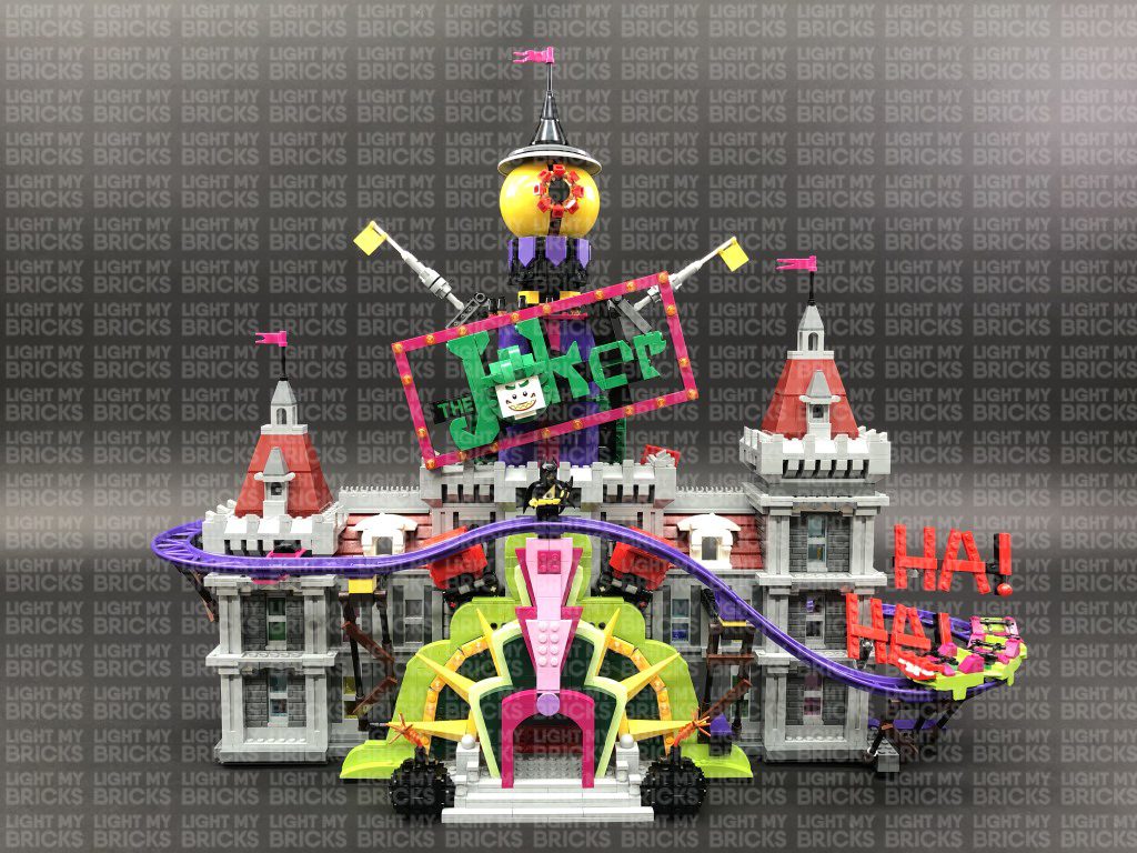
The following page is the instructions for the Light My Bricks LEGO Joker Manor (70922) LED light kit.
If you run into any issues, please refer to the online troubleshooting guide.
To ensure a trouble-free installation of your light kit, please read and follow each step carefully. These instructions can be downloaded in PDF
format here
Please note: This page lists instructions for the LED light kit only. If you are wishing to purchase the Light My Bricks LEGO Joker Manor
(70922) LED light kit , please click here to view the product page
Package Contents:
4x White 30cm Bit Lights
17x White 15cm Bit Lights
12x Flashing White 30cm Bit Lights

12x Flashing White 15cm Bit Lights
2x Blue 30cm Bit Lights
4x White 15cm Micro Bit Lights
8x White Strip Lights
1x Green Strip Lights
2x Multi Colour Strip Lights
1x Micro 2-4 Port Expansion Board
3x 6-Port Expansion Boards
3x 8-Port Expansion Boards
3x 12-Port Expansion Boards
1x Flicker Effects Board
4x 5cm Connecting Cables
8x 15cm Connecting Cables
9x 30cm Connecting Cable
1x USB Power Cable
6x Adhesive Squares
LEGO Pieces:
3x Trans Clear Round Plate 1×1
2x Trans Clear Plate w Rounded Bottom 2×2
Spot Light LEGO Pieces
2x Black Dish Inverted 3×3
2x Black Plate 2×6
2x Black Plate 1×2 modified w Handle on End
2x Black Tile 1×1 w Clip
4x Black Plate 1×2 modified with stud jumper
Important things to note:
Laying cables in between and underneath bricks
Cables can fit in between and underneath LEGO® bricks, plates, and tiles providing they are laid correctly between the LEGO® studs. Do NOT
forcefully join LEGO® together around cables; instead ensure they are laying comfortably in between each stud.

CAUTION: Forcing LEGO® to connect over a cable can result in damaging the cable and light.
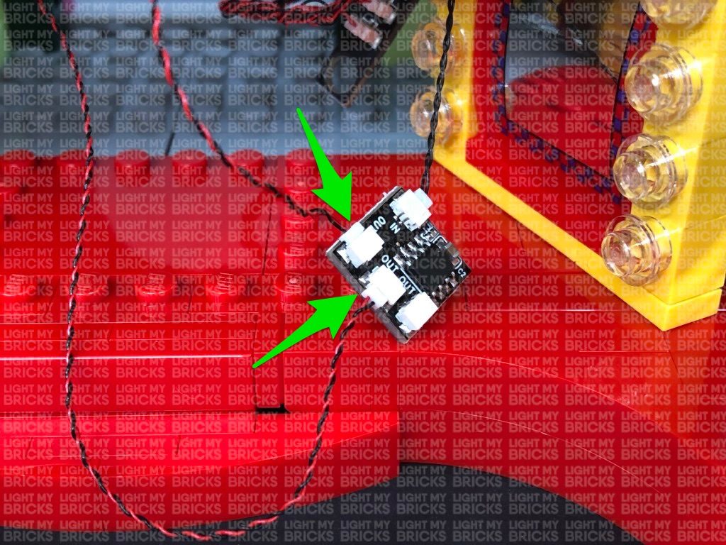
Connecting cable connectors to Expansion Boards
Take extra care when inserting connectors to ports of Expansion Boards. Connectors can be inserted only one way. With the expansion board facing up,
look for the soldered “=” symbol on the left side of the port. The connector side with the wires exposed should be facing toward the soldered “=” symbol
as you insert into the port. If a plug won’t fit easily into a port connector, do not force it.
Incorrectly inserting the connector can can result in bent pins inside the port or possible overheating of the expansion board when
connected.
Connecting cable connectors to Strip Lights
Take extra care when inserting connectors to ports on the Strip Lights. Connectors can be inserted only one way. With the Strip Light facing up, ensure
the side of the connector with the wires exposed is facing down. If a plug won’t fit easily into a port connector, don’t force it. Doing so will damage the
plug and the connector.


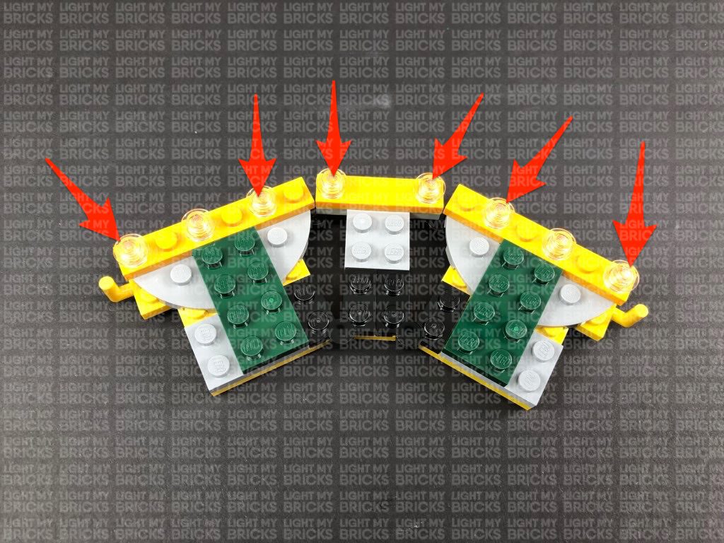
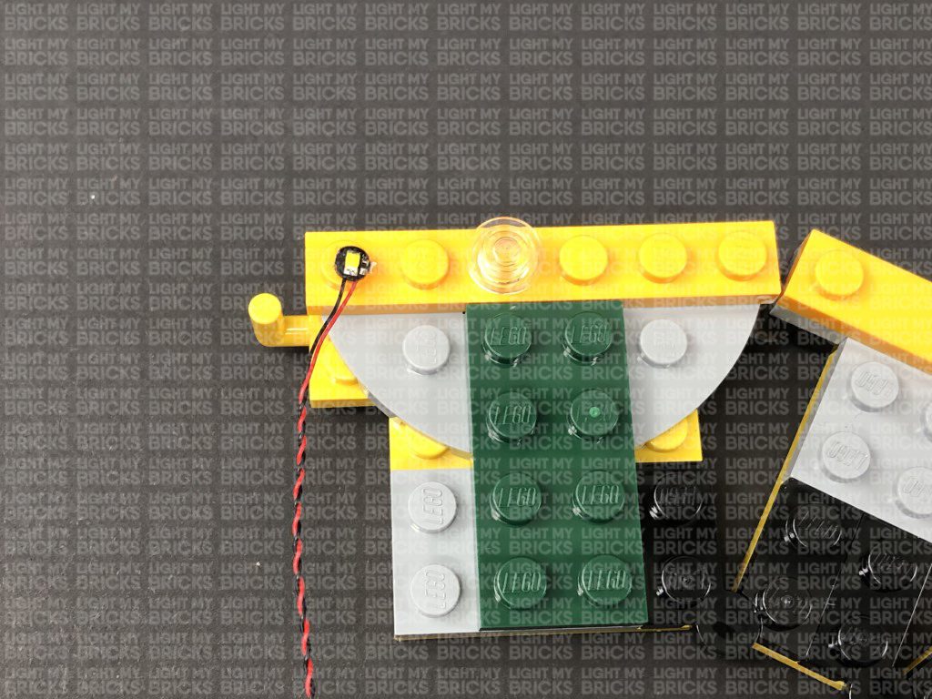
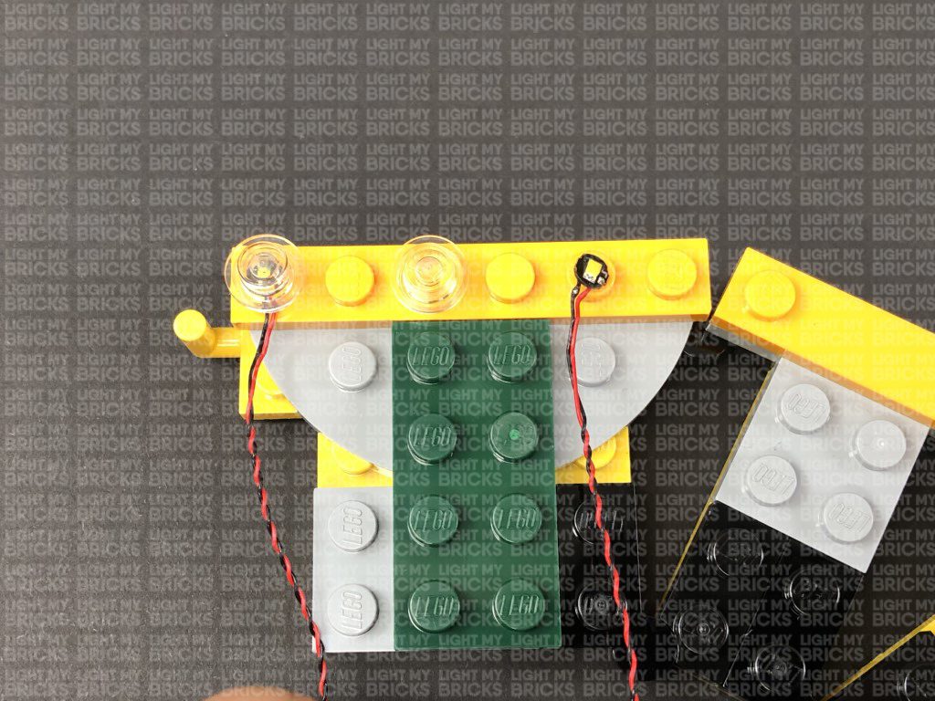
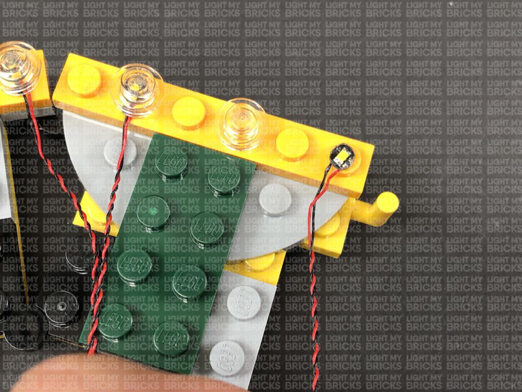
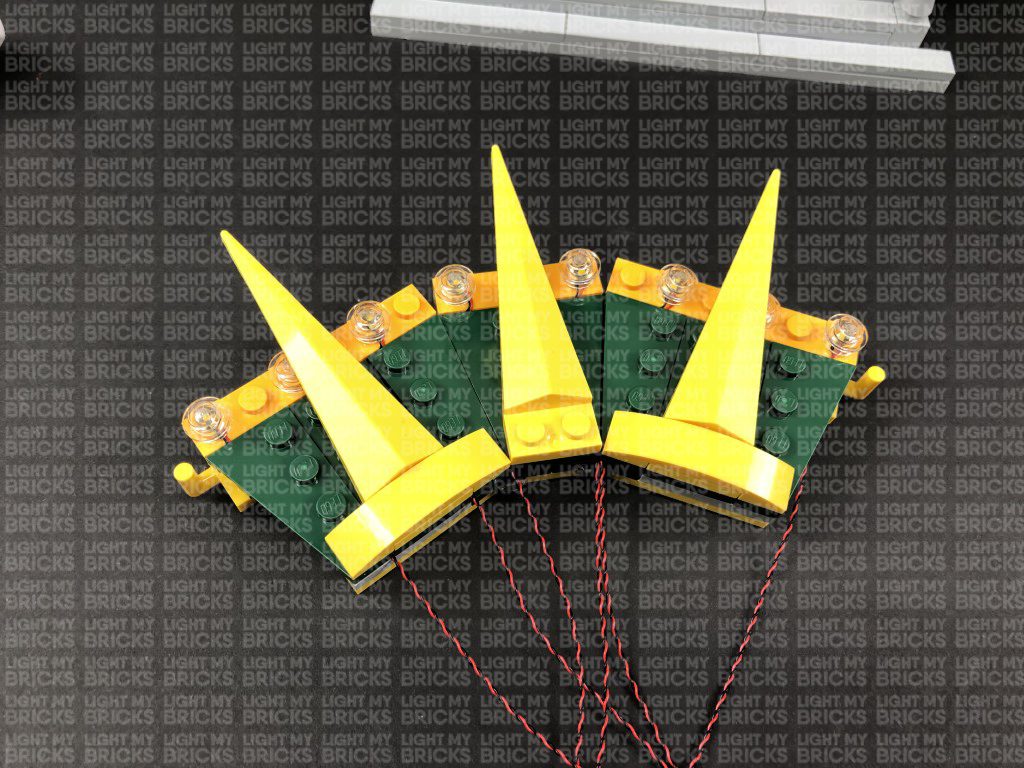
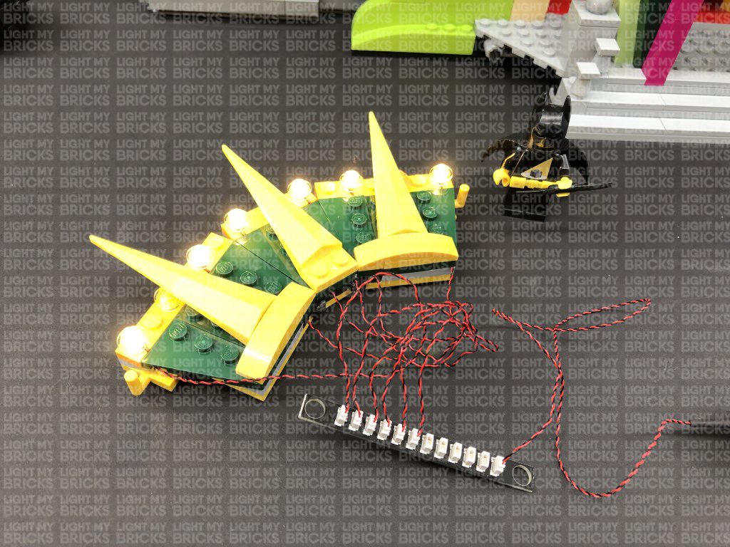
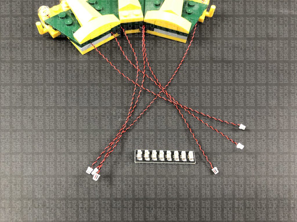
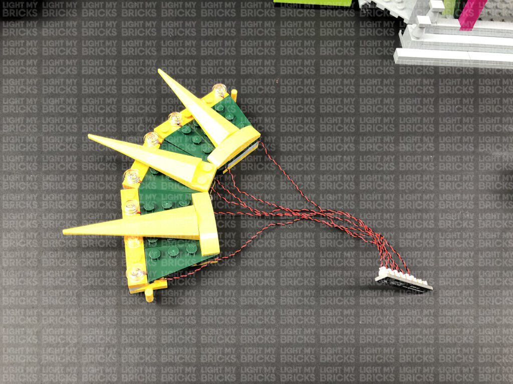
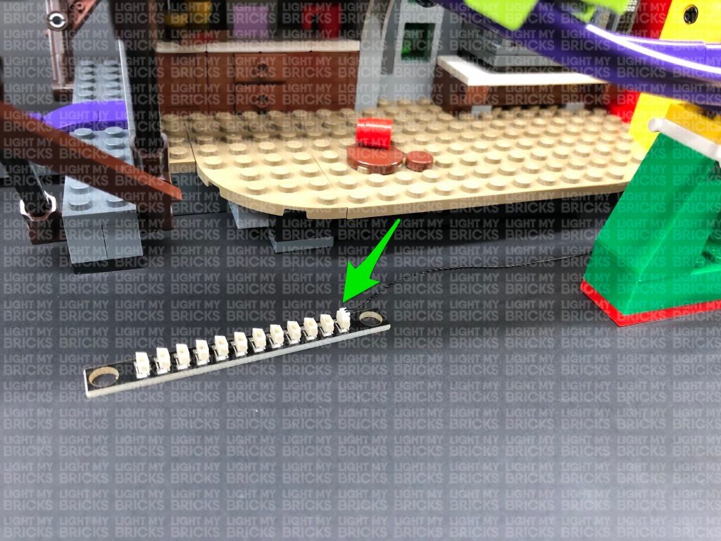
Take a White 15cm Bit Light and with the cable facing down, place it over the far left stud on this section. Secure the Bit Light in place by
reconnecting one of the trans clear round plates over the top.
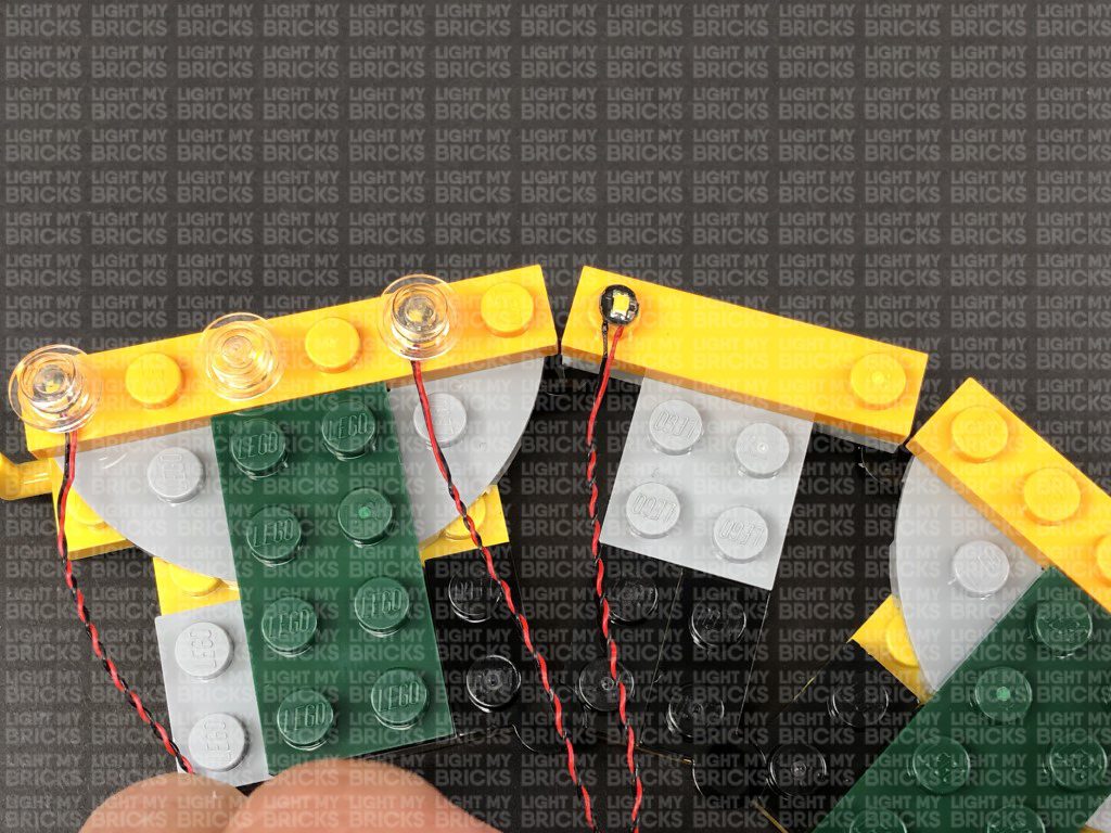
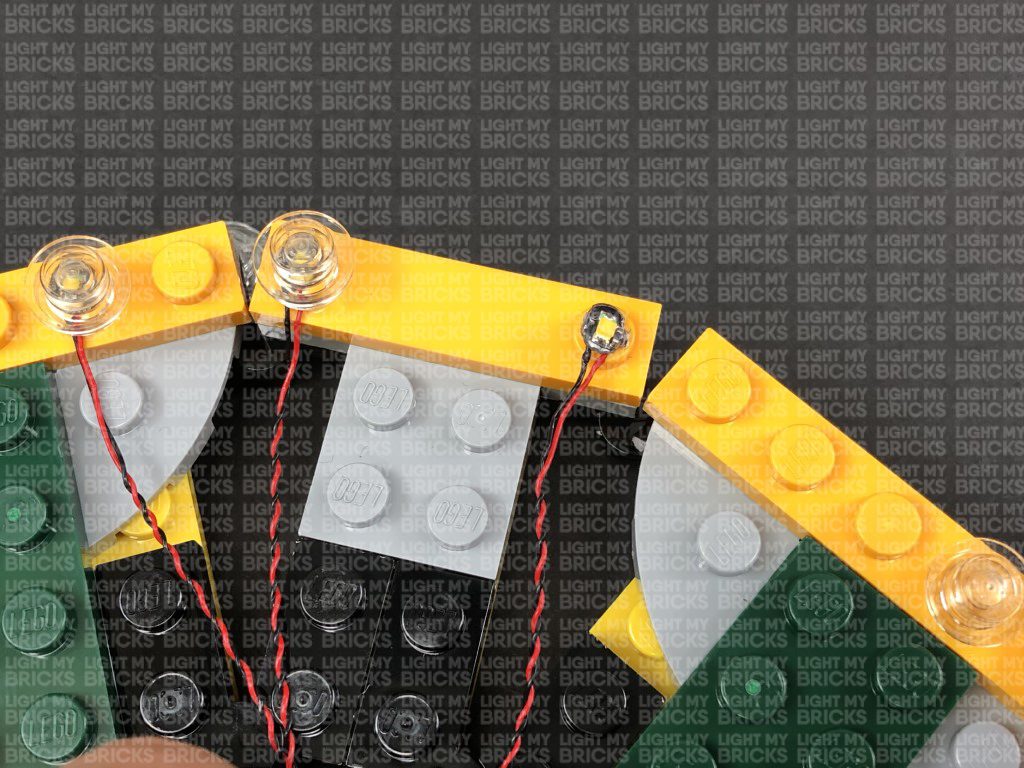
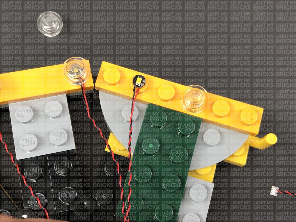
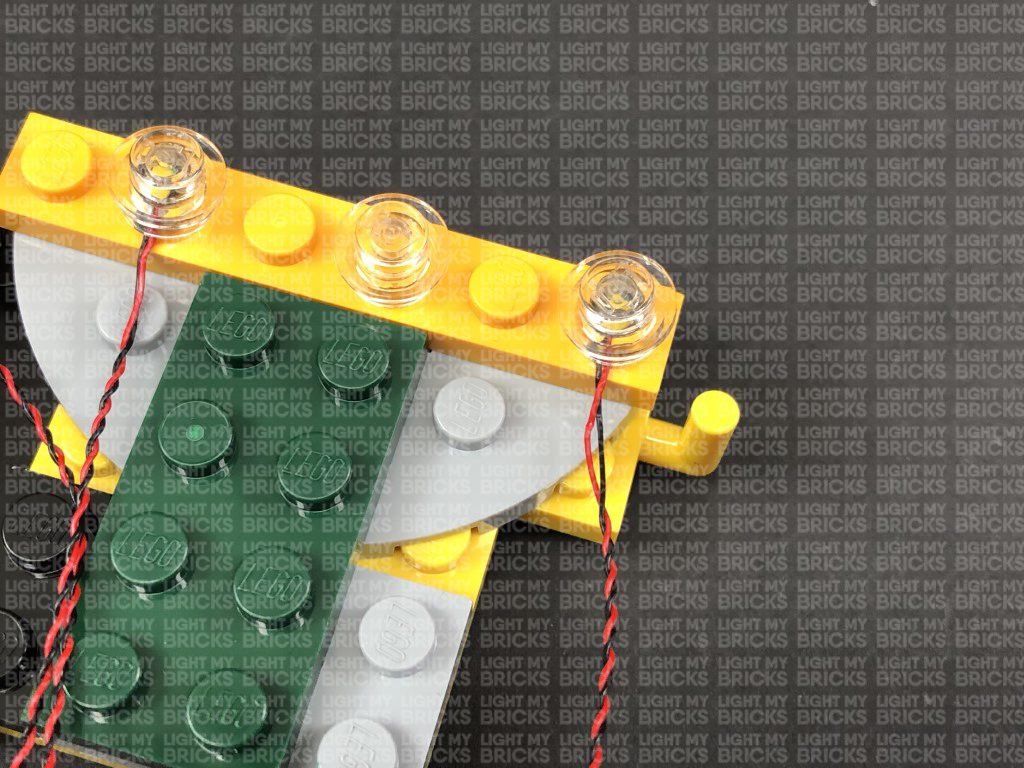
3.) Repeat previous step to install another 5x White 15cm Bit Lights to this section as shown below:

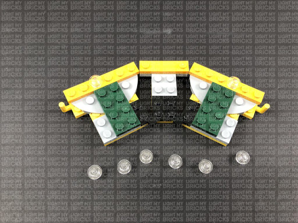
Fold the cables down at the edge of the yellow plates, then reconnect the pieces we removed earlier. Folding the cables down will prevent them from
snapping when you reconnect pieces over the top. Ensure the cables underneath plates are laid in between studs.
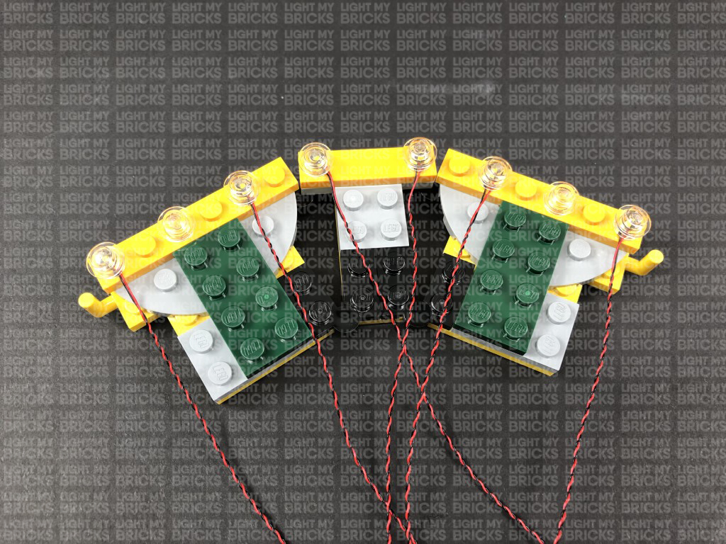
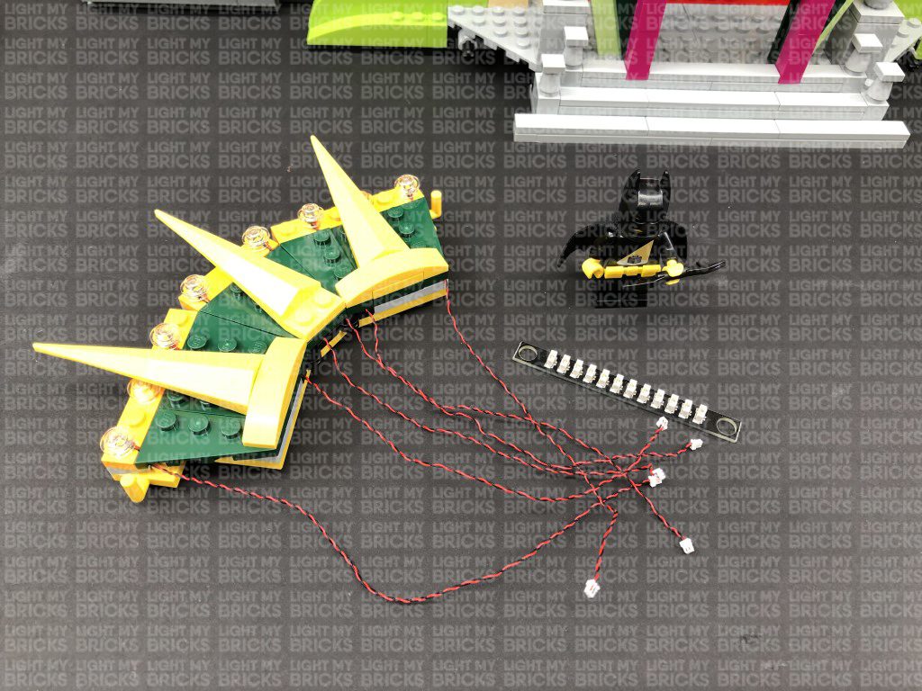
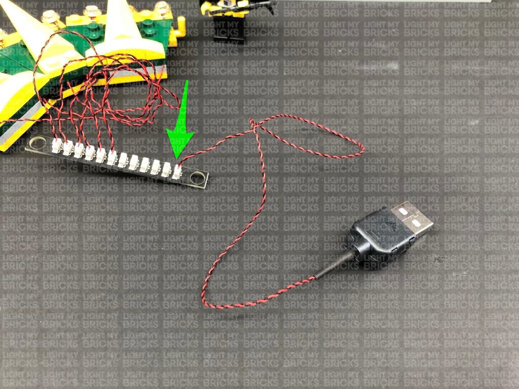
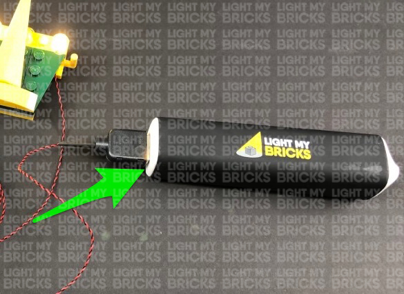
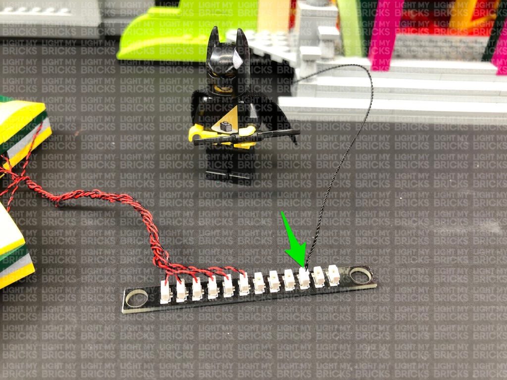
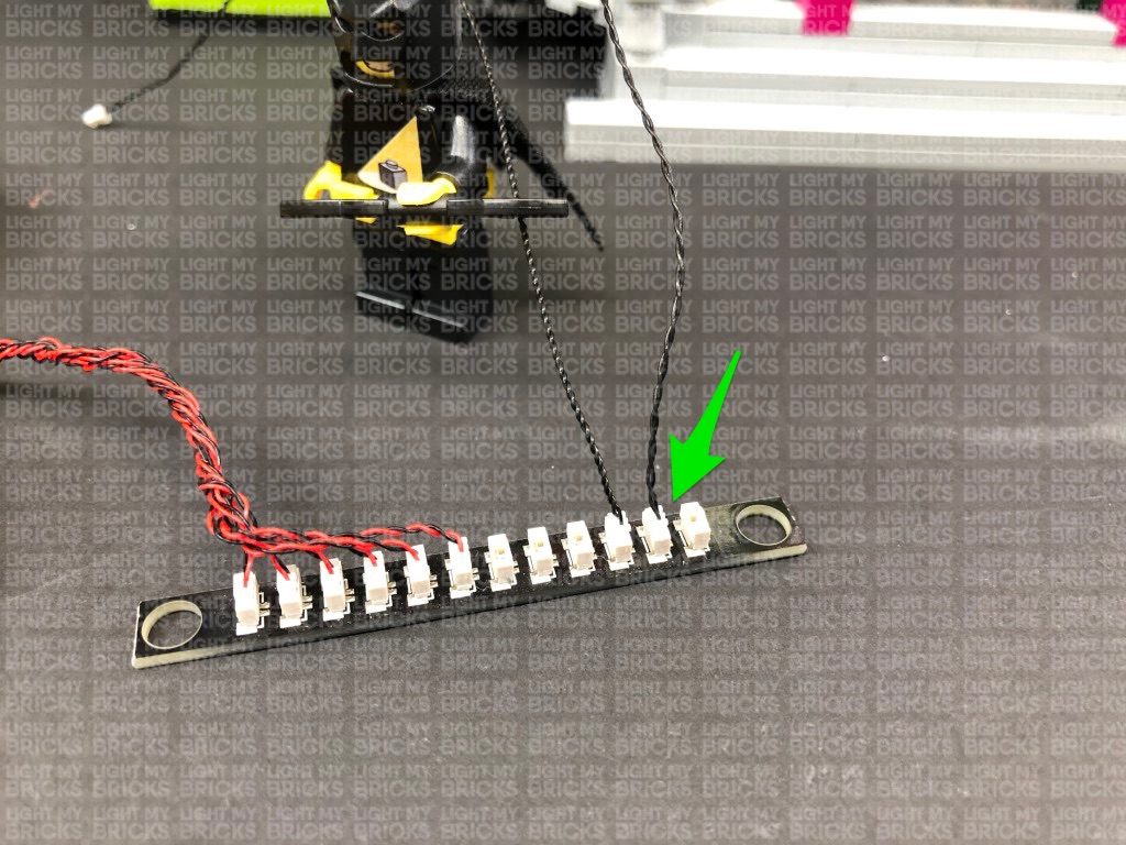
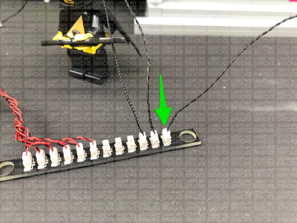
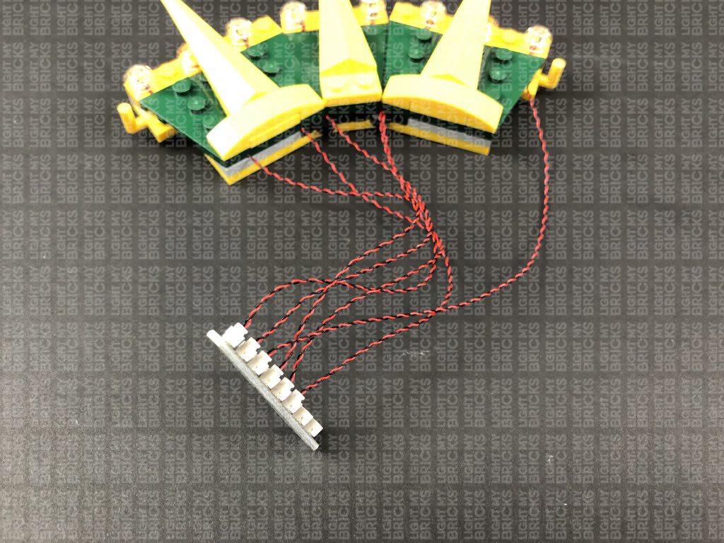
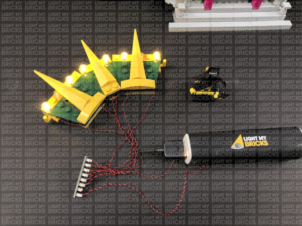
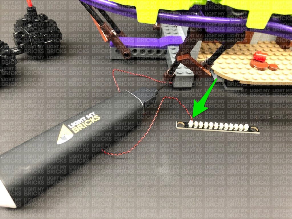
4.) Take a 12-Port Expansion Board and connect all six cables to it. Take a USB Power Cable and connect it to the expansion board, then connect
the other end of it to your USB Power Bank (sold separately) . Turn the power bank ON to test all lights are working OK.

Note: If you experience any issues with the lights not working and suspect an issue with a component, please try a different port on the
expansion board to verify where the fault lies (with the light or expansion board). To correct any issues with expansion board ports, please
view the section addressing expansion board issues on our online troubleshooting guide.
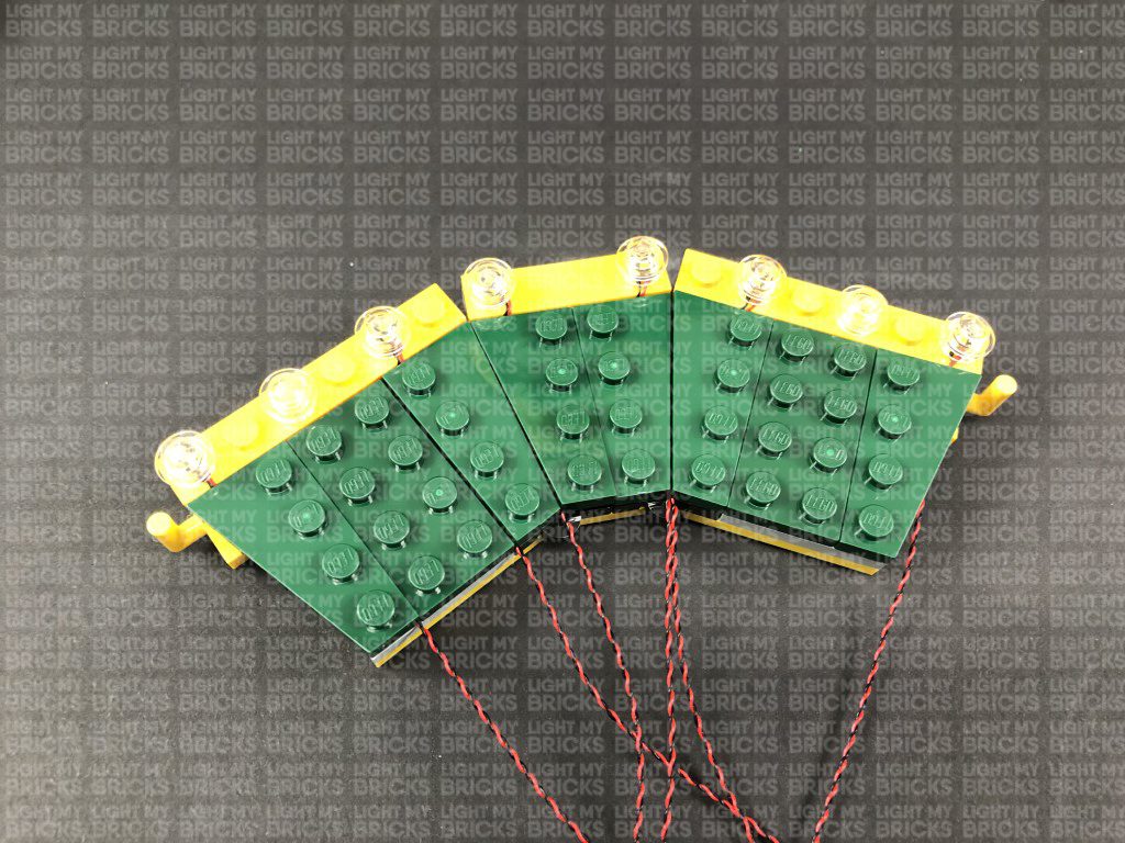
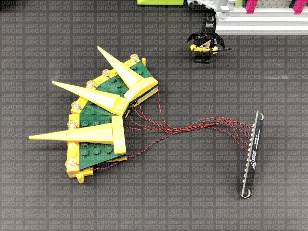
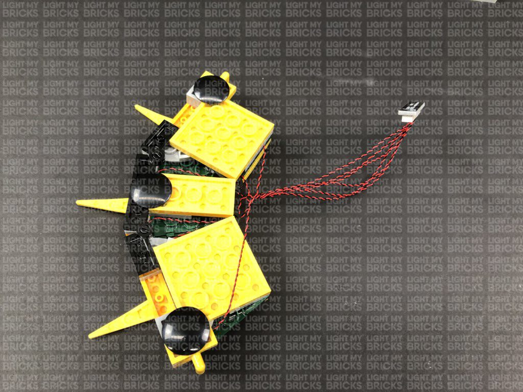
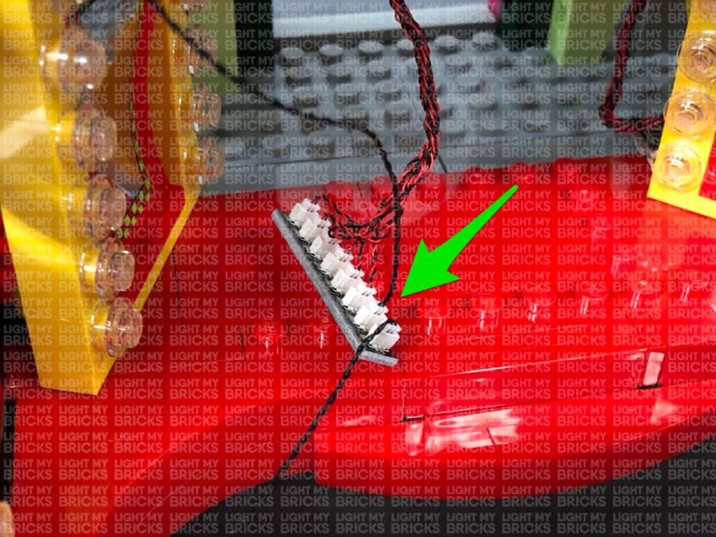
Disconnect the USB Power Cable from the expansion board, then turn the light section over and bring all six cables together and twist/wind them around
each other closest to the top. Continue to twist/wind the cables all the way to the end so they come together to form a larger neat cable.

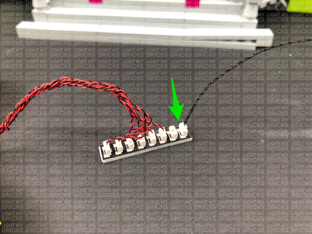
5.) Take 3x 30cm Connecting Cables and connect one end of each of them to the 12-port Expansion Board.
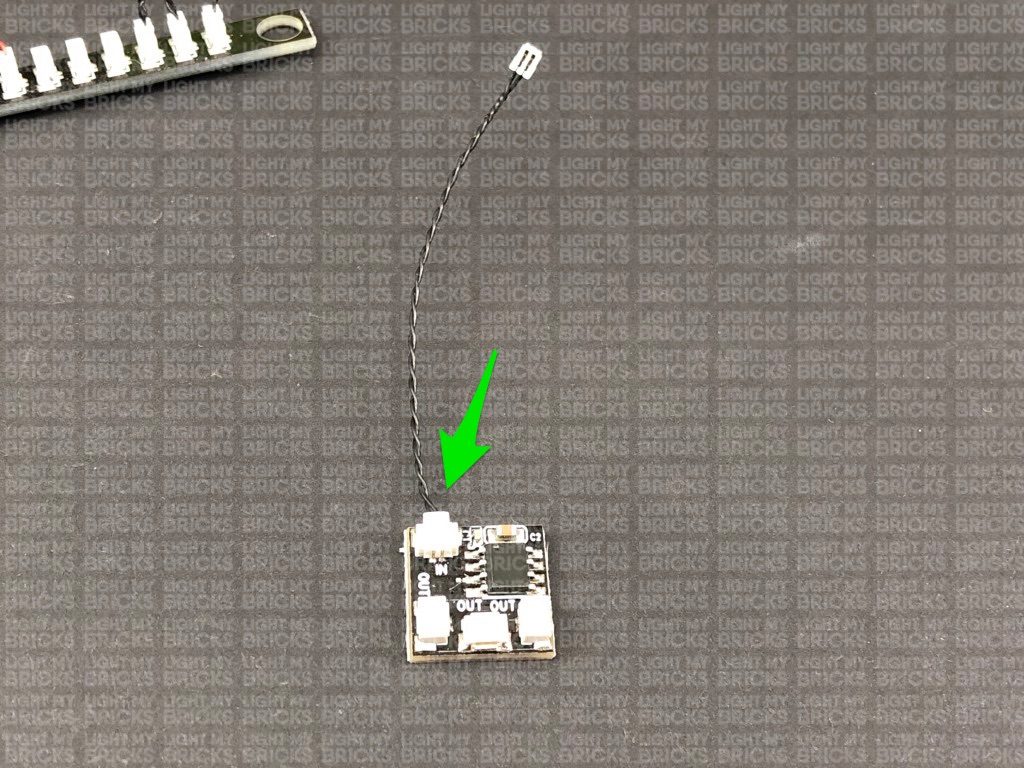
Take a Flicker Effects Board and connect a 5cm Connecting Cable to the IN port. Connect the other end of the cable to the 12-port expansion board.
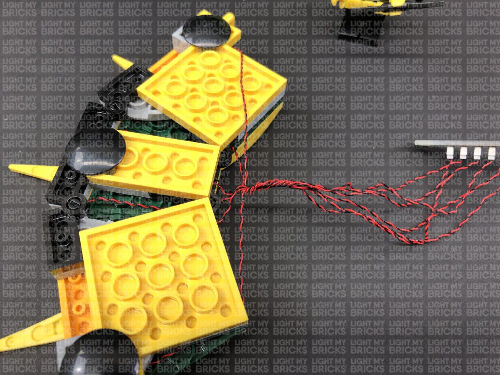
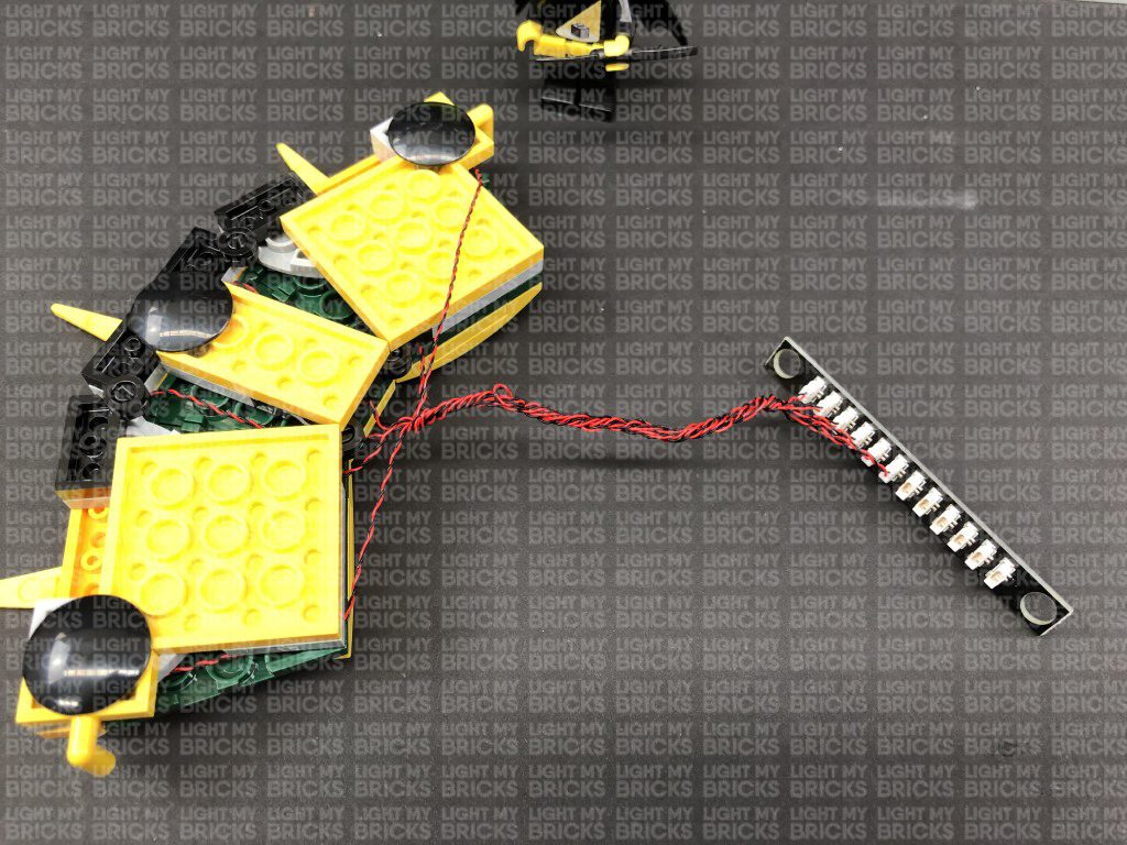
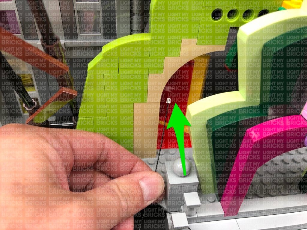
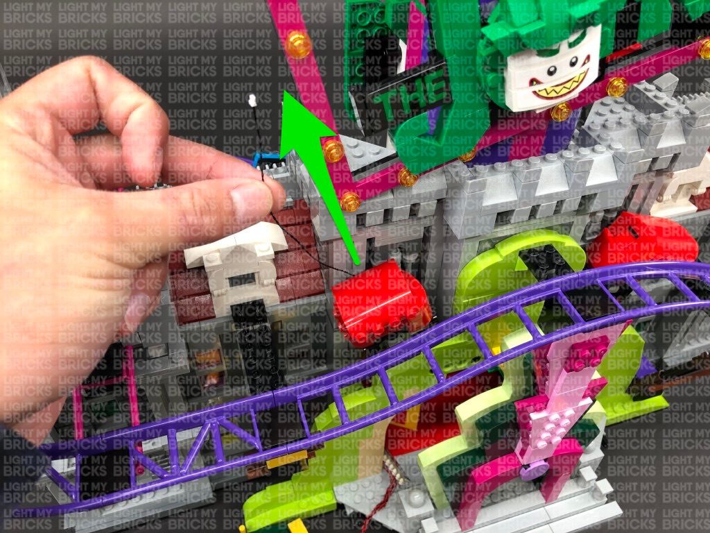
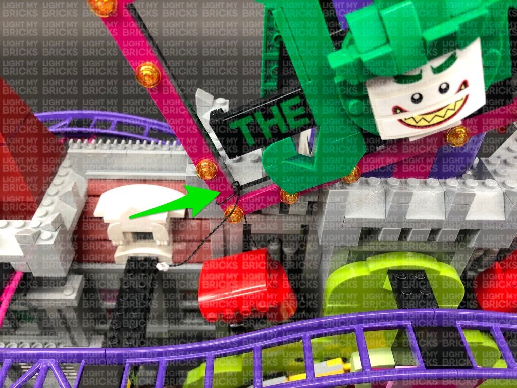
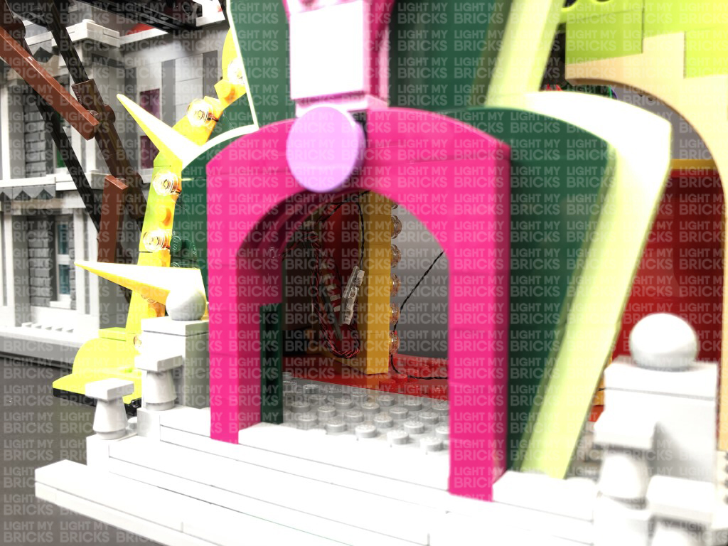
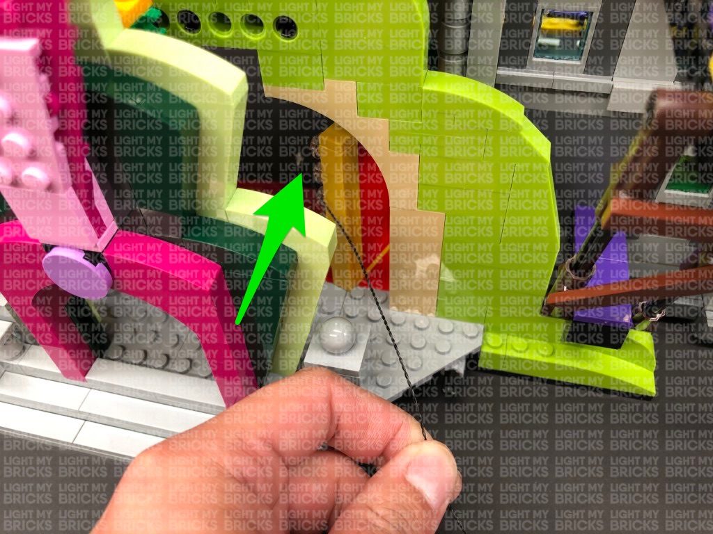
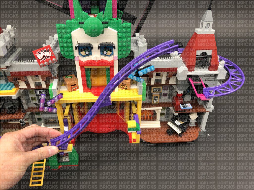
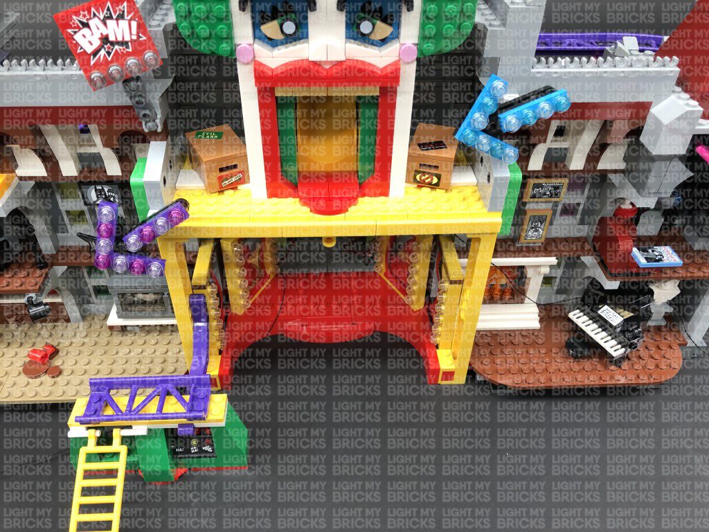
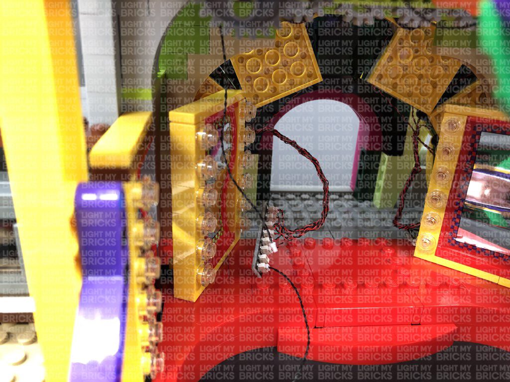
6.) Take the other of the last 30cm Connecting Cable connected to the 12-port expansion board and thread it through the left side of the entrance space.
Pull it out from the other side and pull it all the way up behind the left “boxing glove”. Secure the cable underneath the bottom of the “Joker” sign by
looping it around the frame a few times. Reconnect the left light section of the entrance using the clip on top as shown below:


Note: If you experience any issues with the lights not working and suspect an issue with a component, please try a different port on the
expansion board to verify where the fault lies (with the light or expansion board). To correct any issues with expansion board ports, please
view the section addressing expansion board issues on our online troubleshooting guide.
Disconnect the USB Power Cable from the expansion board, then turn the light section over and bring all six cables together and twist/wind them around
each other closest to the top. Continue to twist/wind the cables all the way to the end so they come together to form a larger neat cable.
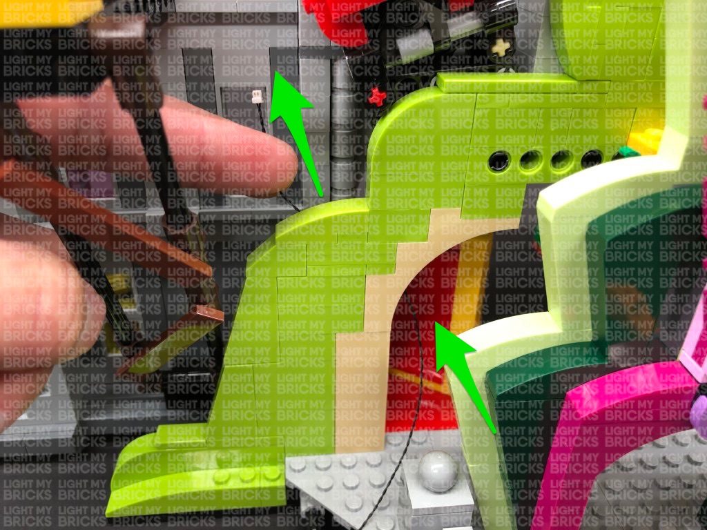
9.) Take a new 30cm Connecting Cable and connect it to the 8-port expansion board. Thread the other end of the cable through the entrance before
reconnecting this right side section to the front of the building.
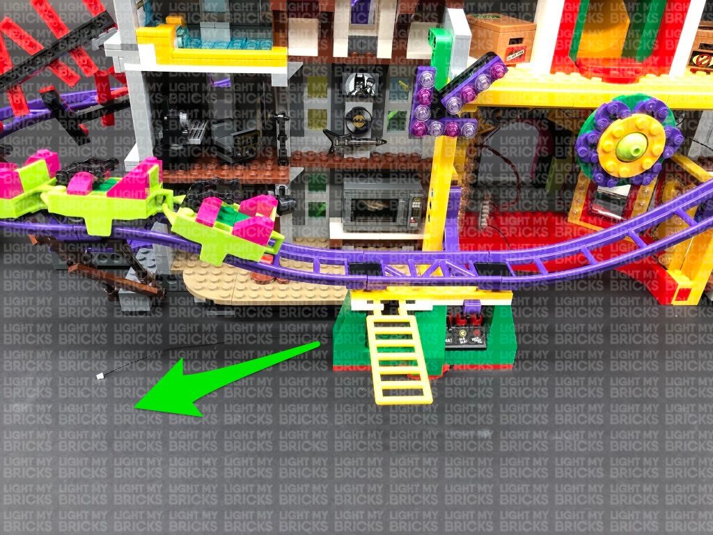
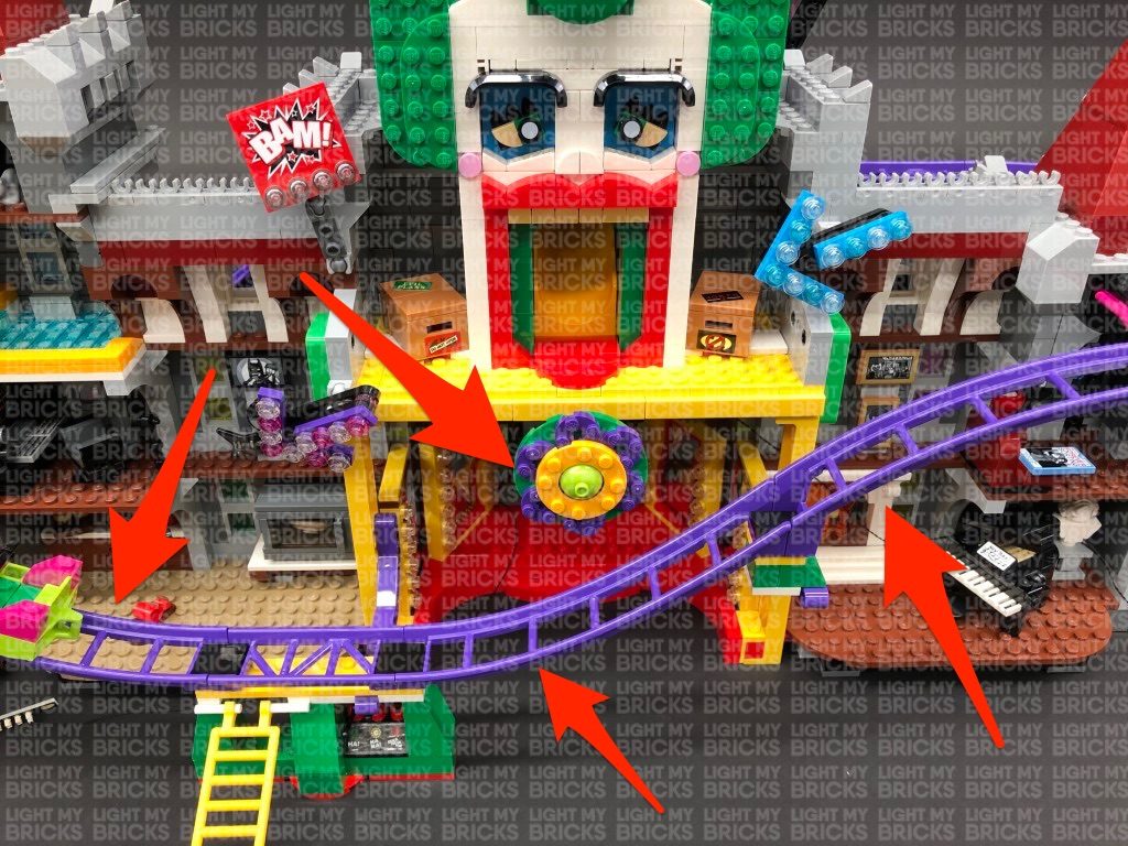
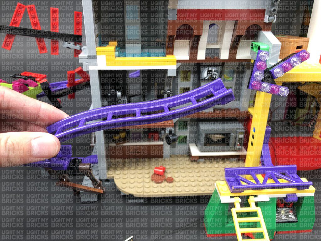
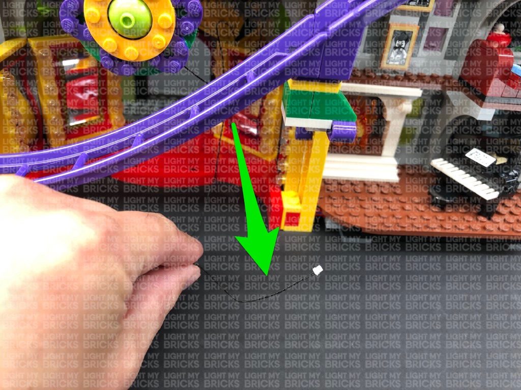
Turn the Joker Manor around to the back side and pull the other end of the 30cm Connecting Cable out and feed it toward the left underneath the roller
coaster track. Connect the cable to a new 12-Port Expansion Board then connect the USB power Cable (connected to the USB Power Bank) to the
expansion board.


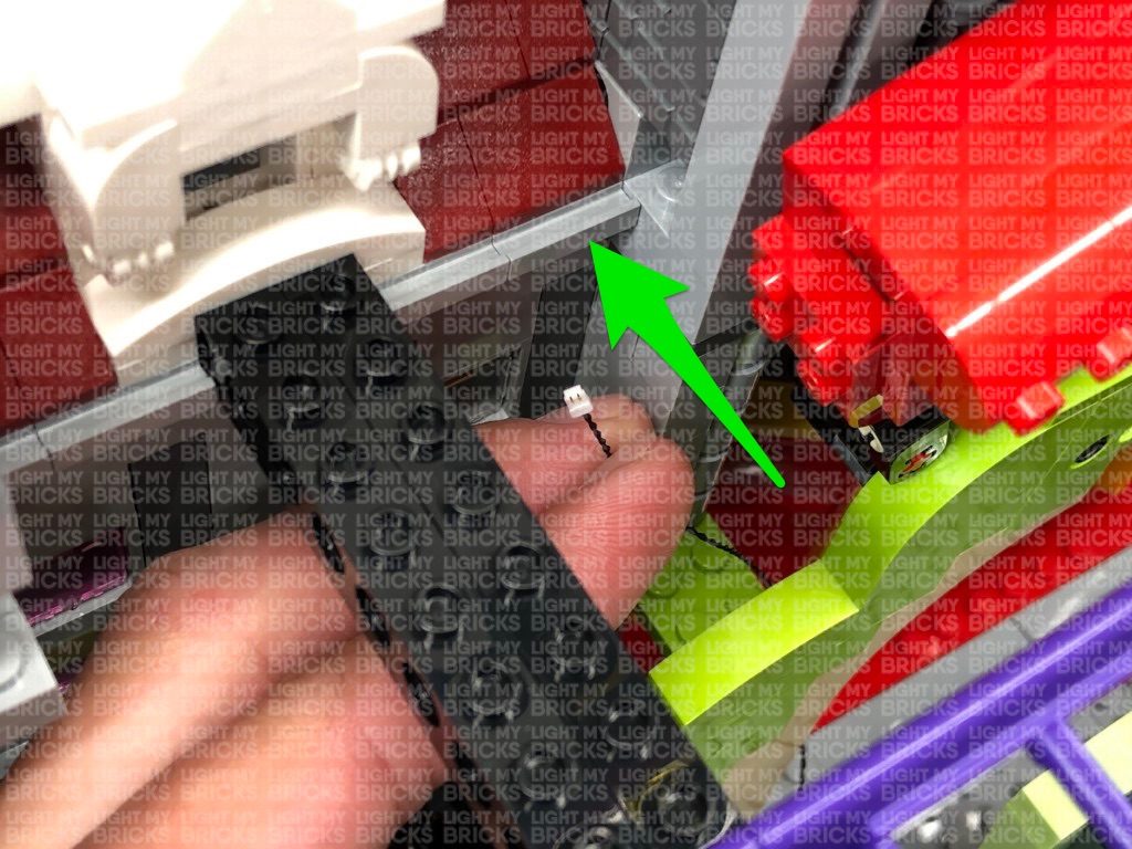
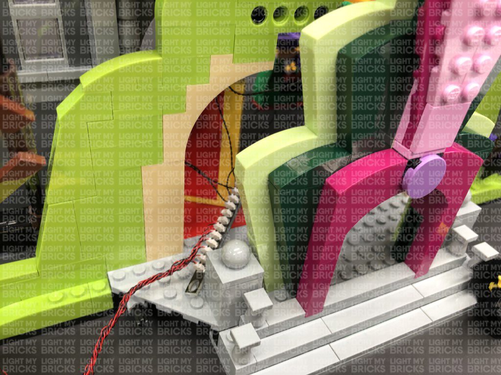
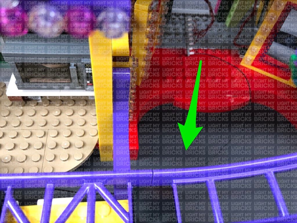
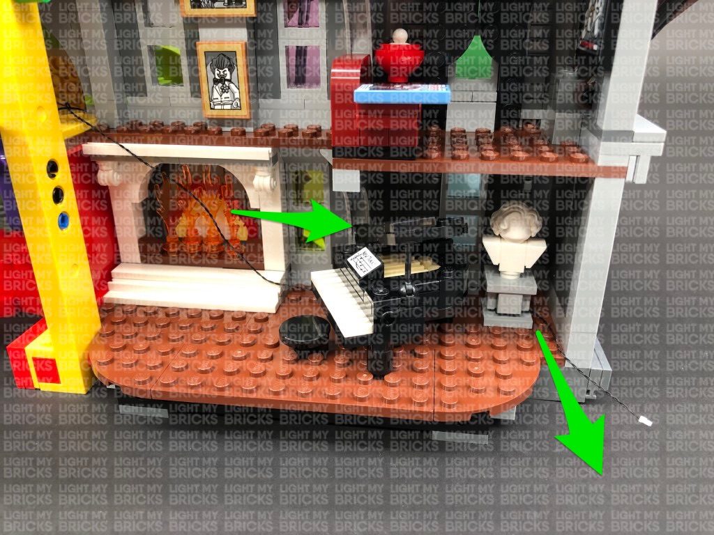
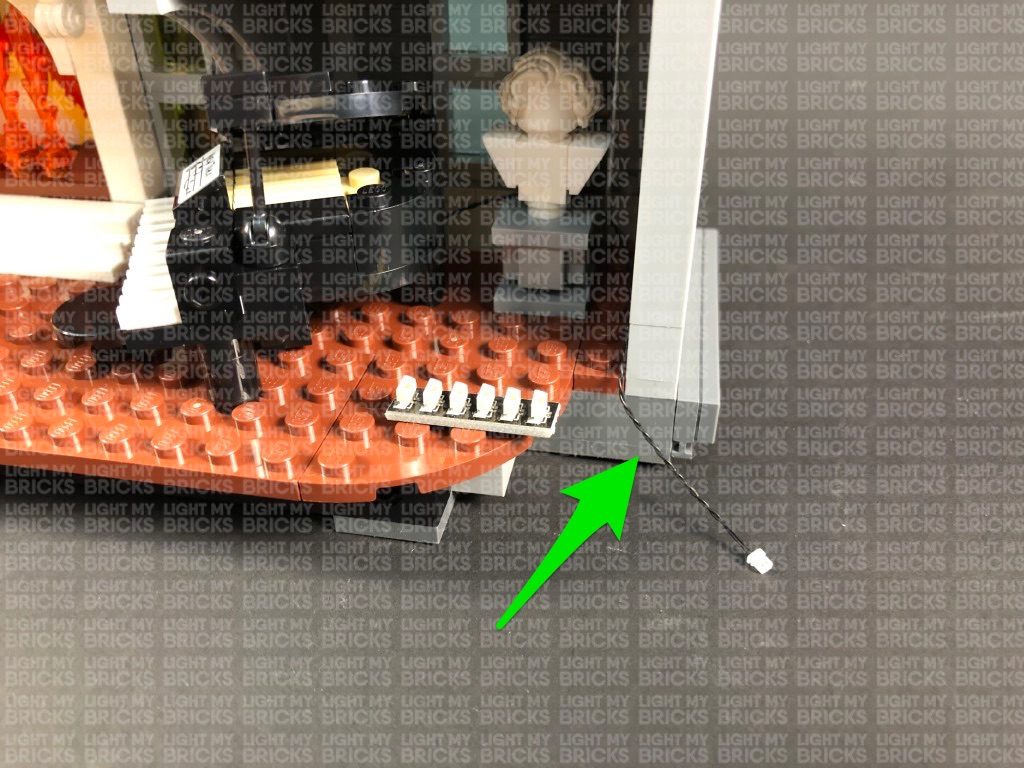
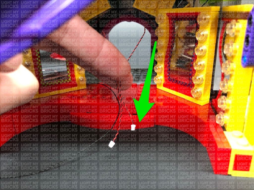
space on the right over the fire place. Pull the cable all the way out then thread it behind the piano and white bust as shown below:
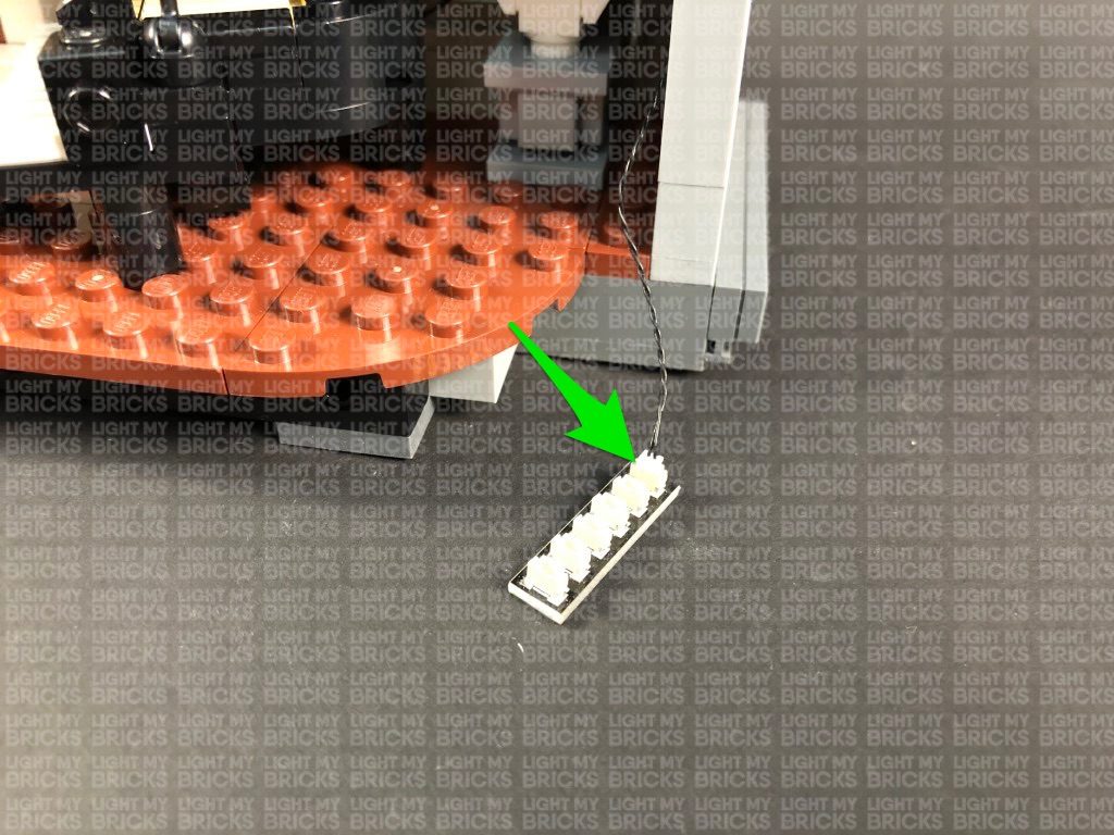
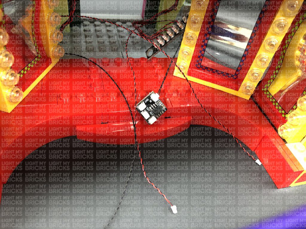
Take a 6-Port Expansion Board and connect the other end of the 30cm Connecting Cable to it.
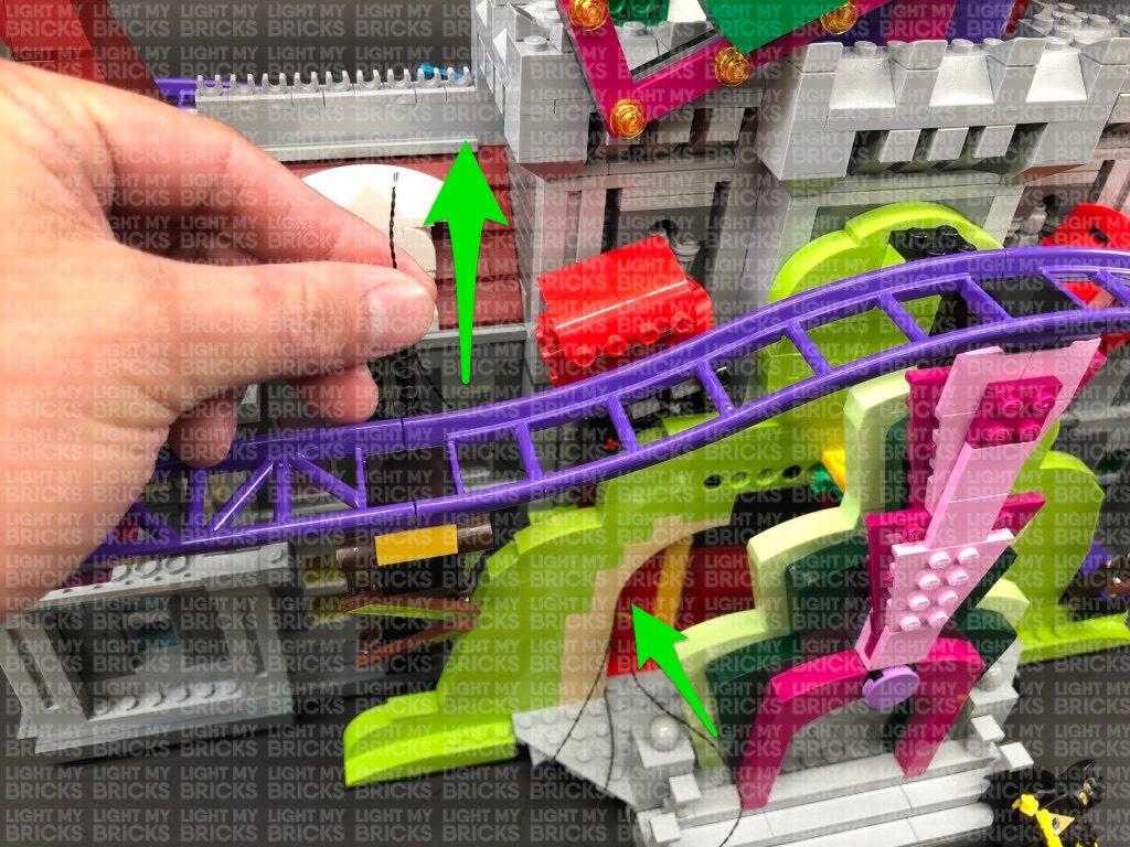
12.) Take the other end of the other 30cm Connecting Cable from the left entrance light section (12-port expansion board) and pull it out and thread it
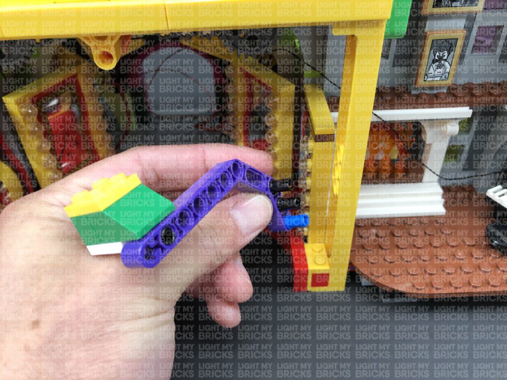
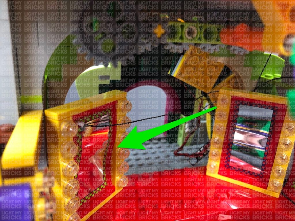
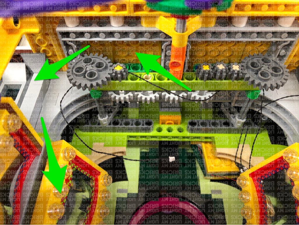
over right side of the ceiling technic pieces (grey gears) directly above. Pull the cable all the way out over the technic pieces as shown below.

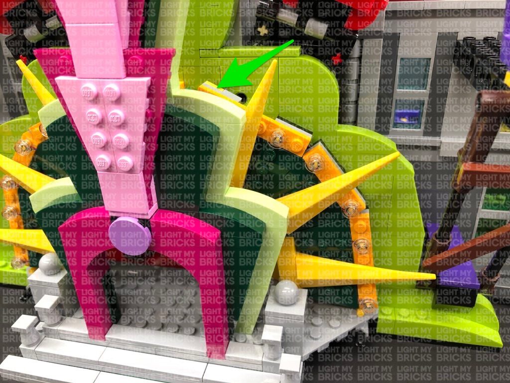
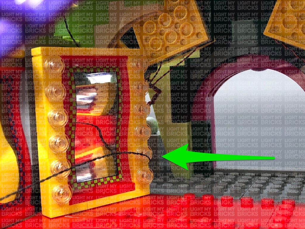
Thread the cable through over the technic pieces (grey gears) on the left side as shown below. Pull the cable down all the way out over the left side
behind the first yellow mirror.
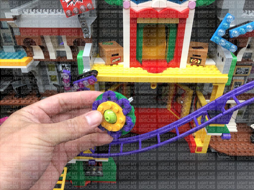
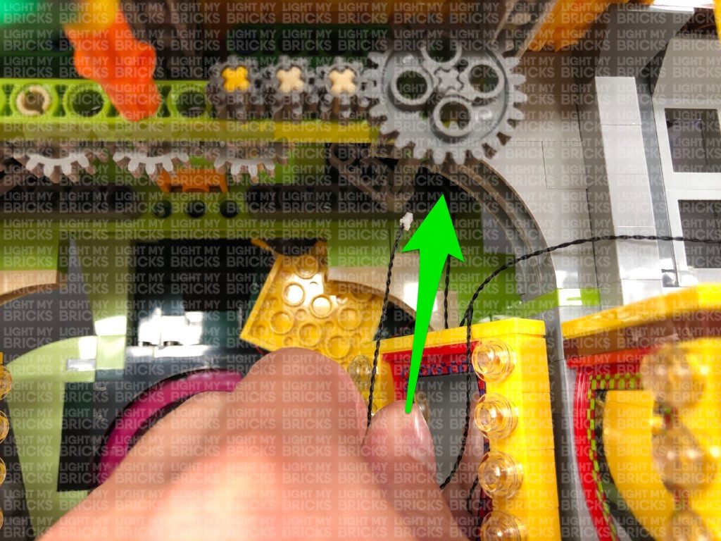
Take caution when threading the cable over the technic gears. Ensure the cable is laid out of the way of the gear teeth as we don’t want
the cable getting caught when we operate the boxing gloves function.
Connect the 30cm Connecting Cable to the 8-port Expansion Board nearby, then tuck the expansion board behind the mirror to the left.
Turn your USB Power Bank ON to test all the lights at the front entrance are working OK.
Note: If you experience any issues with the lights not working and suspect an issue with a component, please try a different port on the
expansion board to verify where the fault lies (with the light or expansion board). To correct any issues with expansion board ports, please
view the section addressing expansion board issues on our online troubleshooting guide.

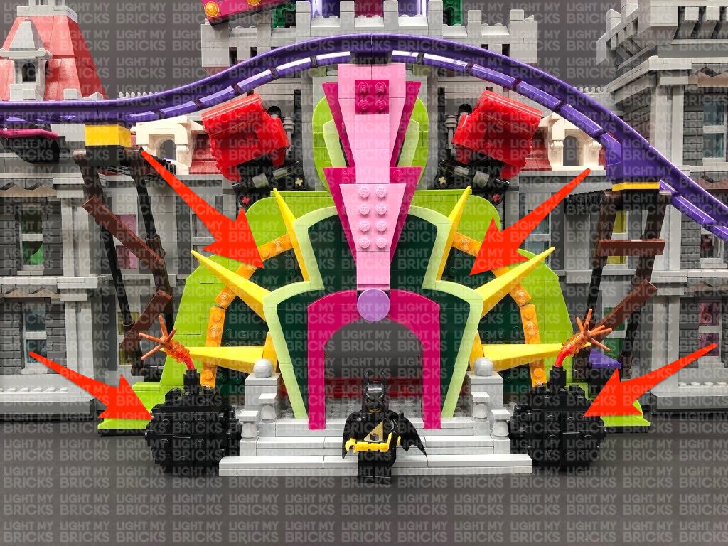
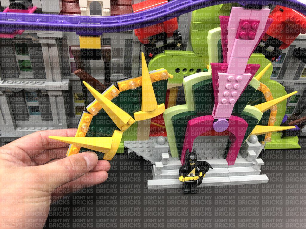
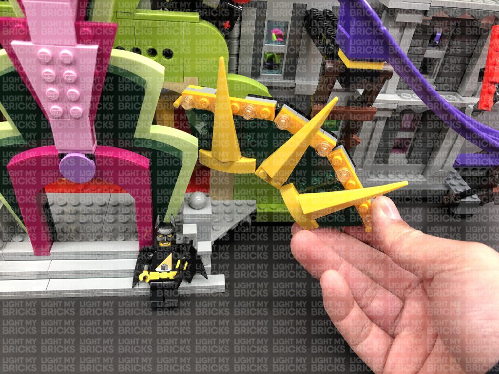
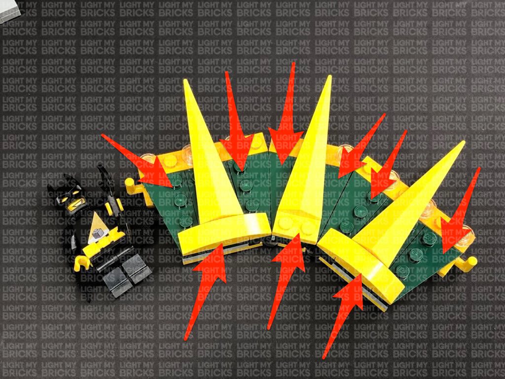
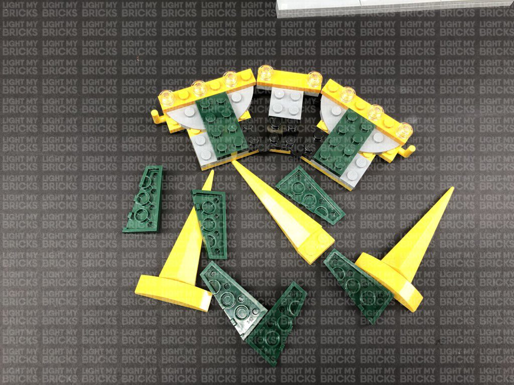
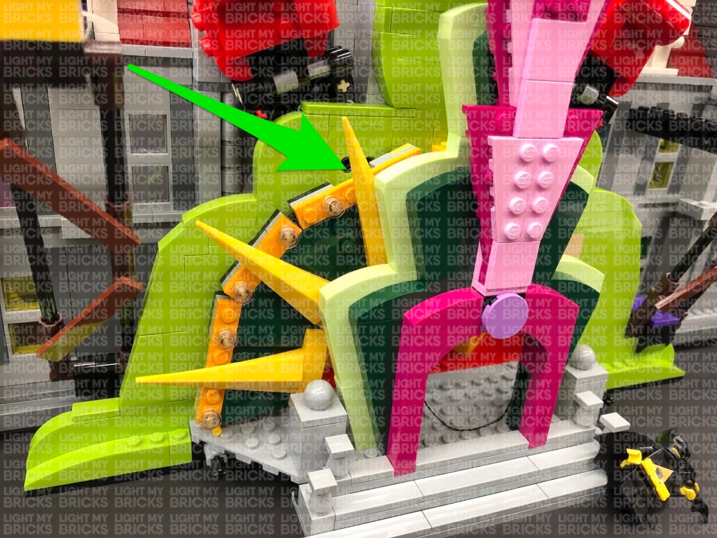
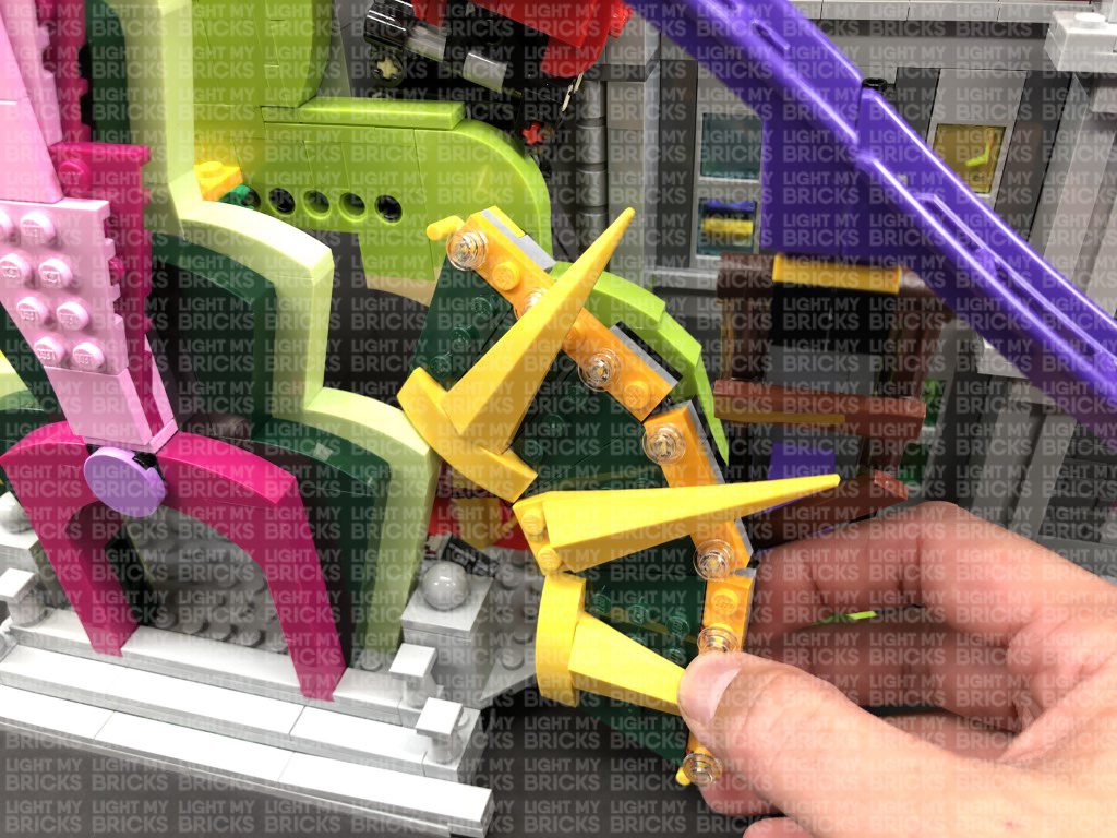
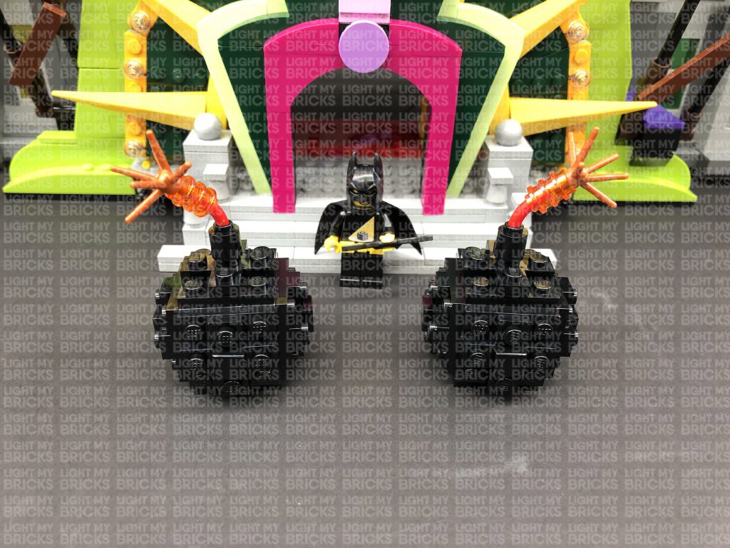
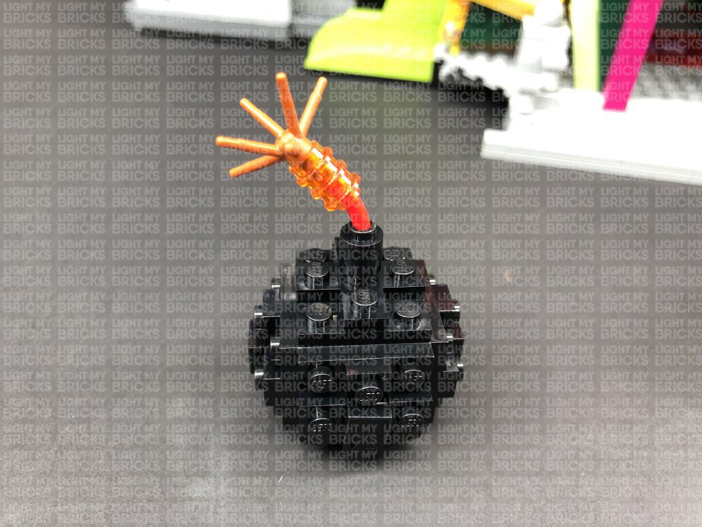
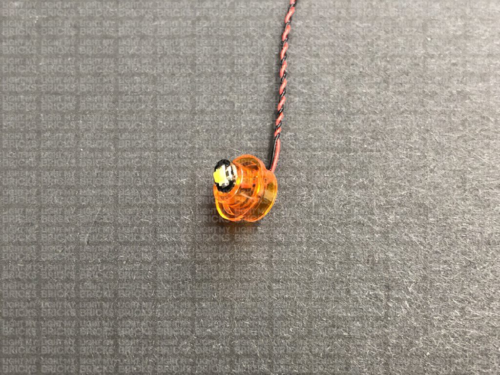
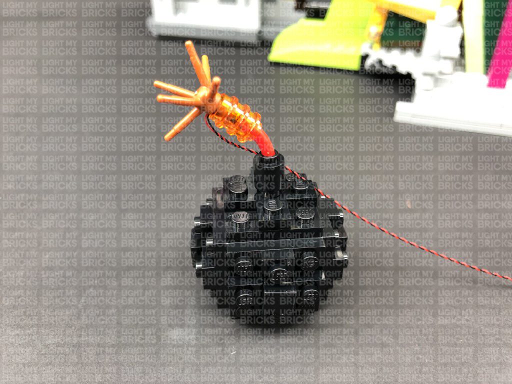
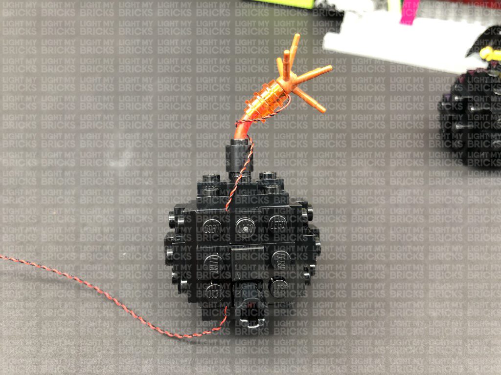
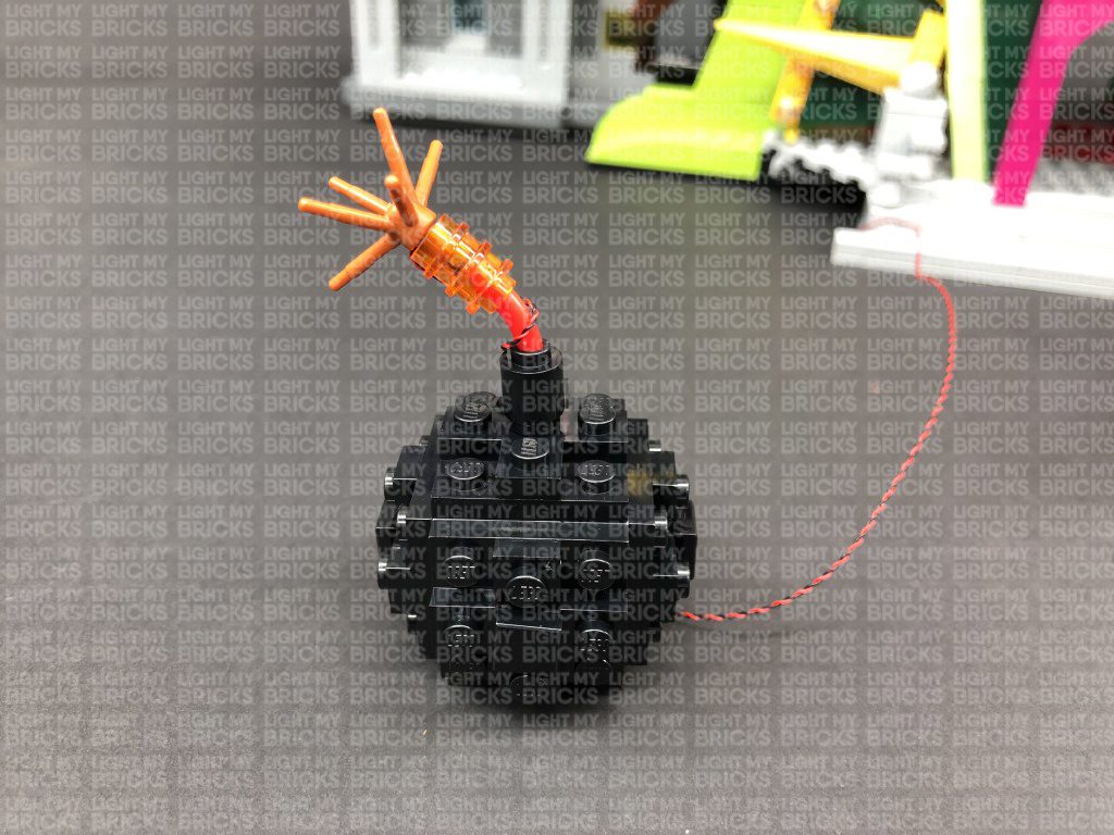
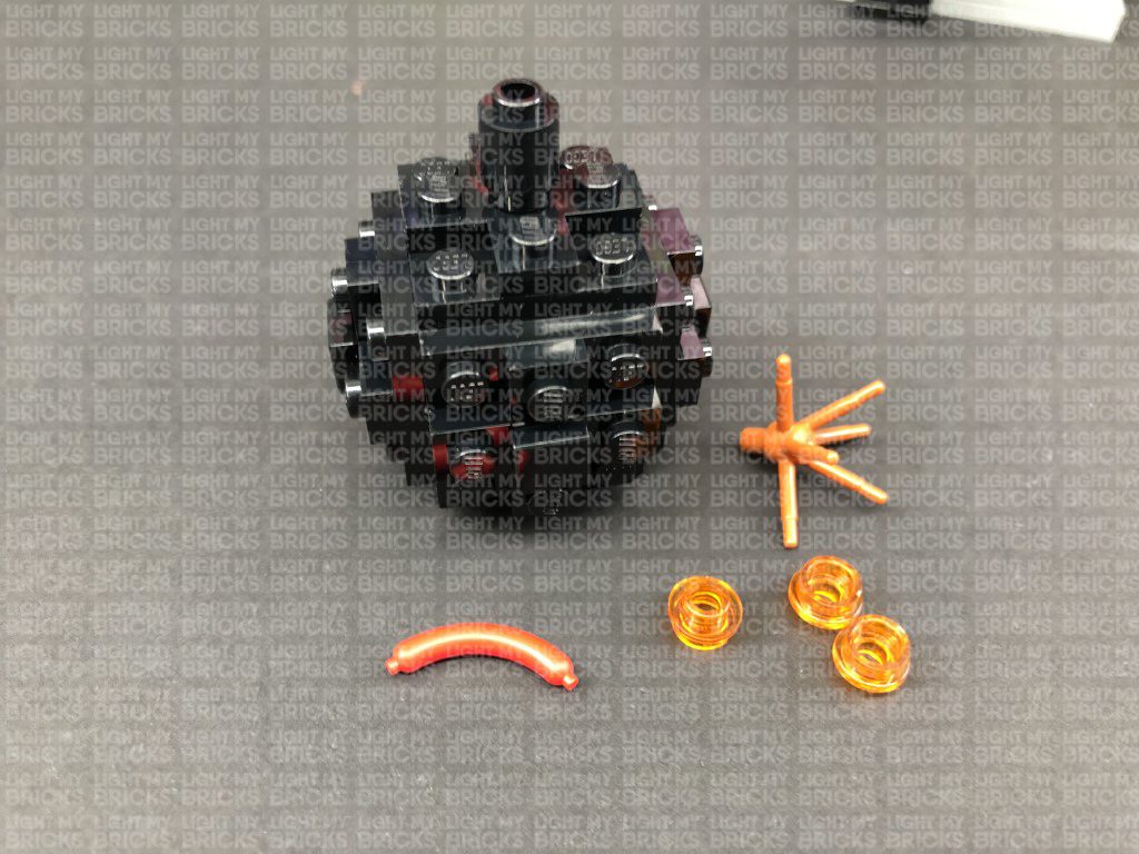
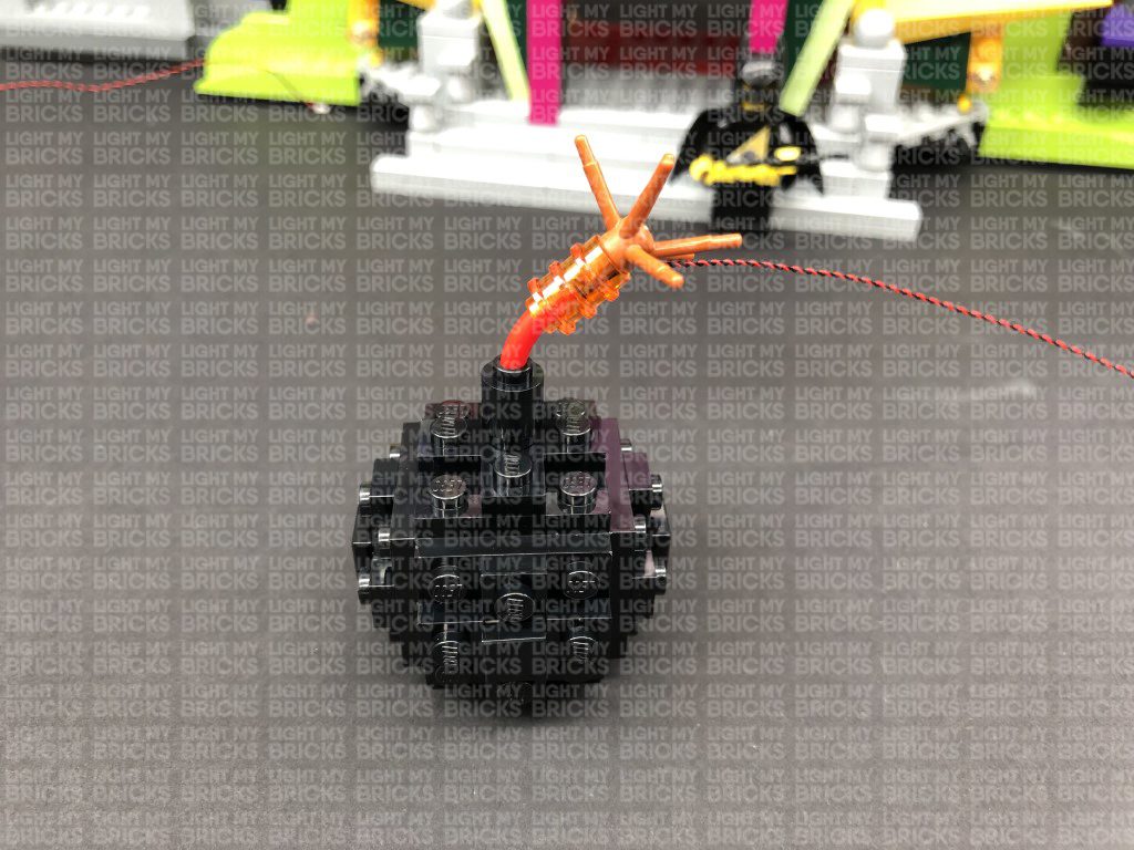
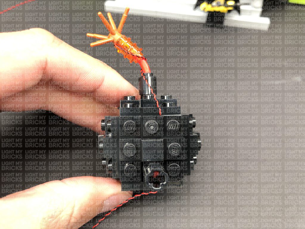
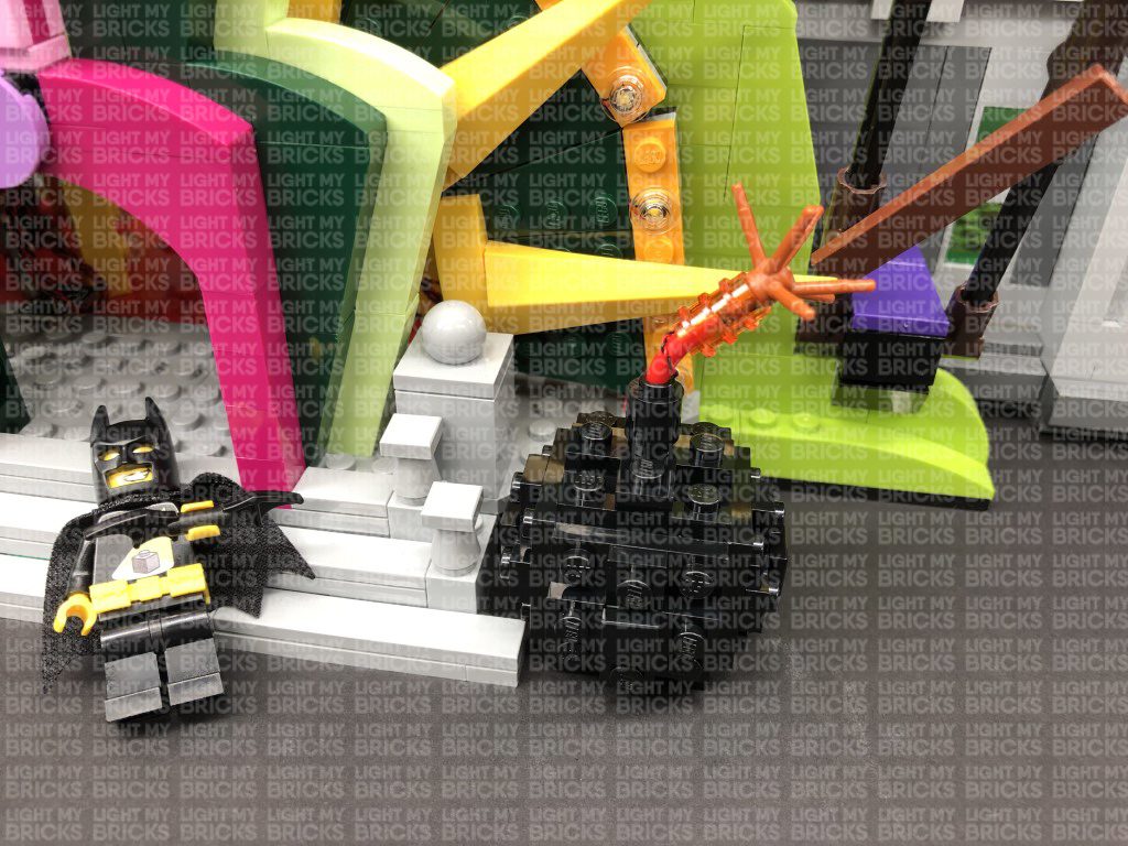
13.) We will now light up the cherry bombs on either side of the front entrance. First take the left bomb and disassemble the top spark pieces as shown
below:
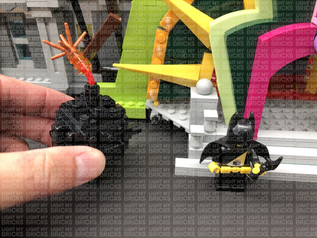
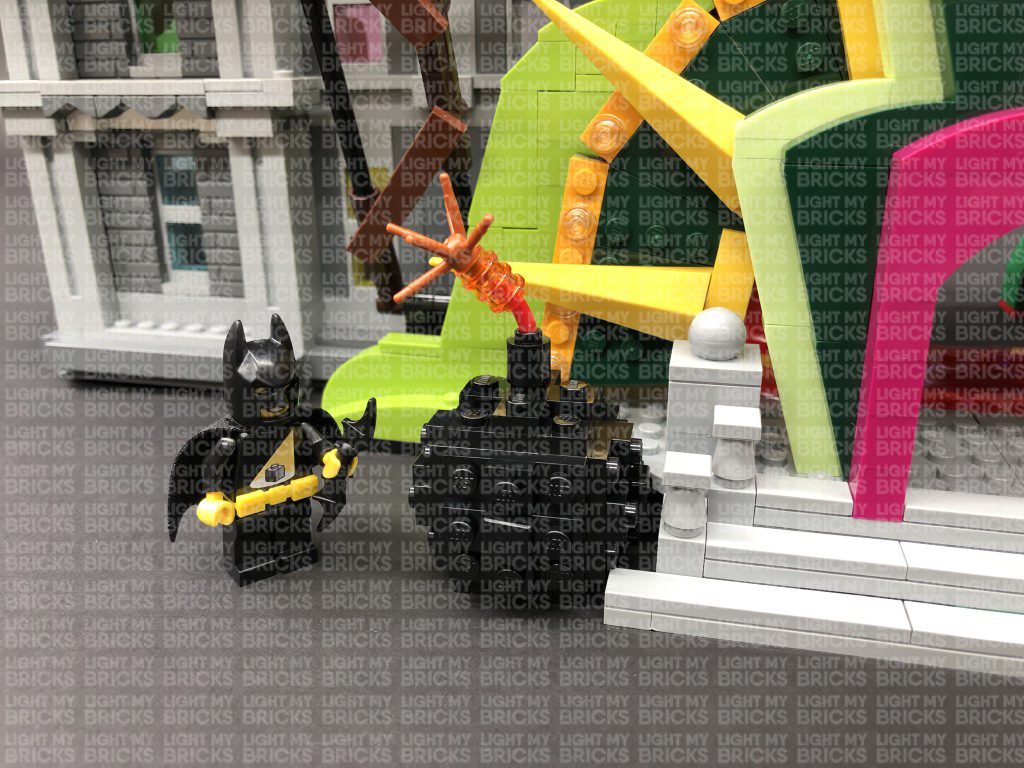
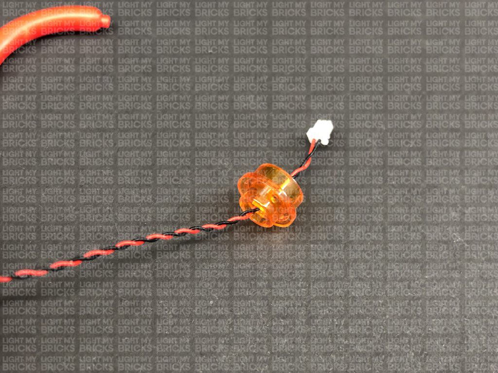
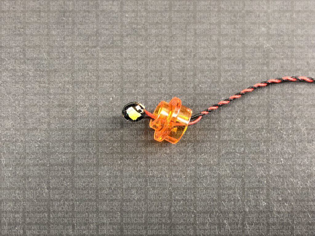
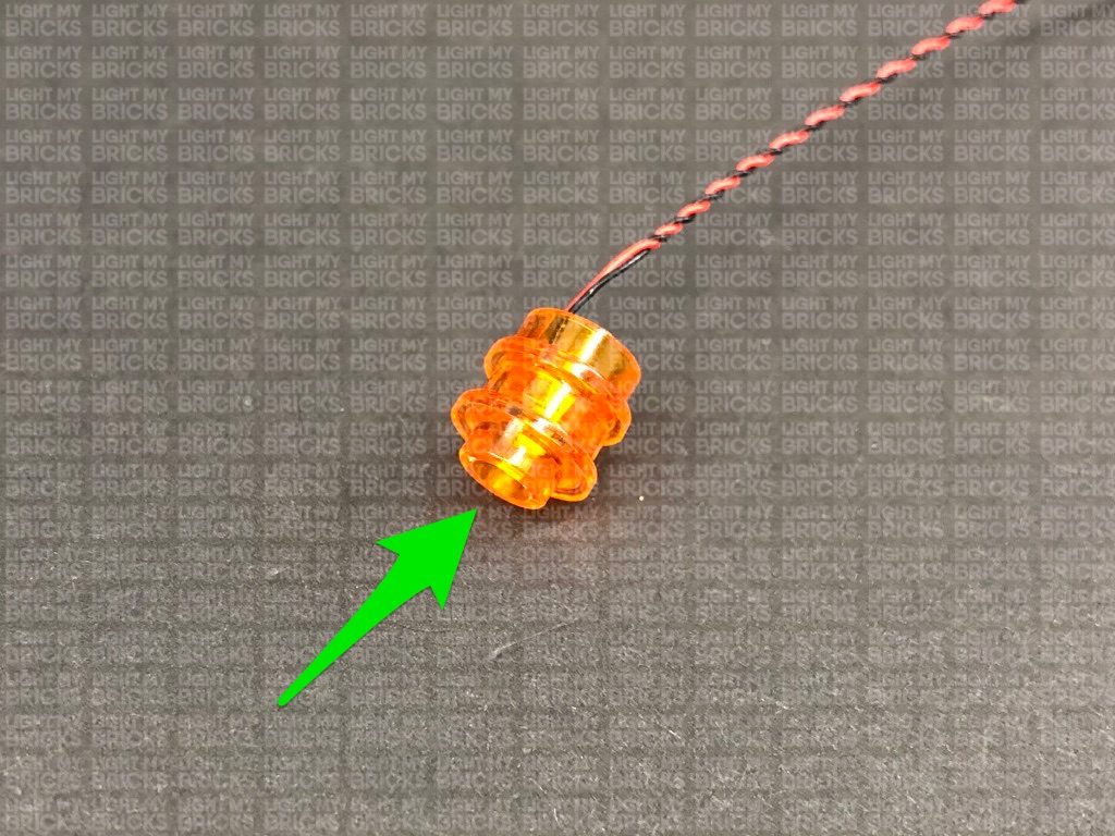
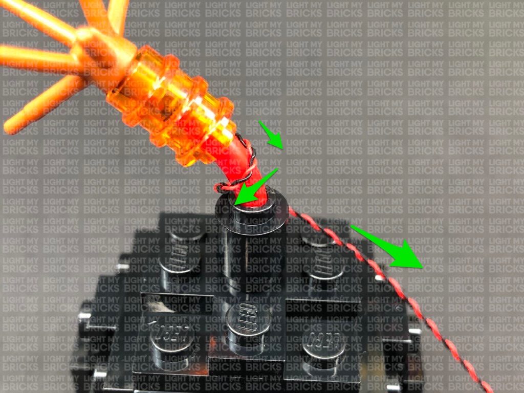
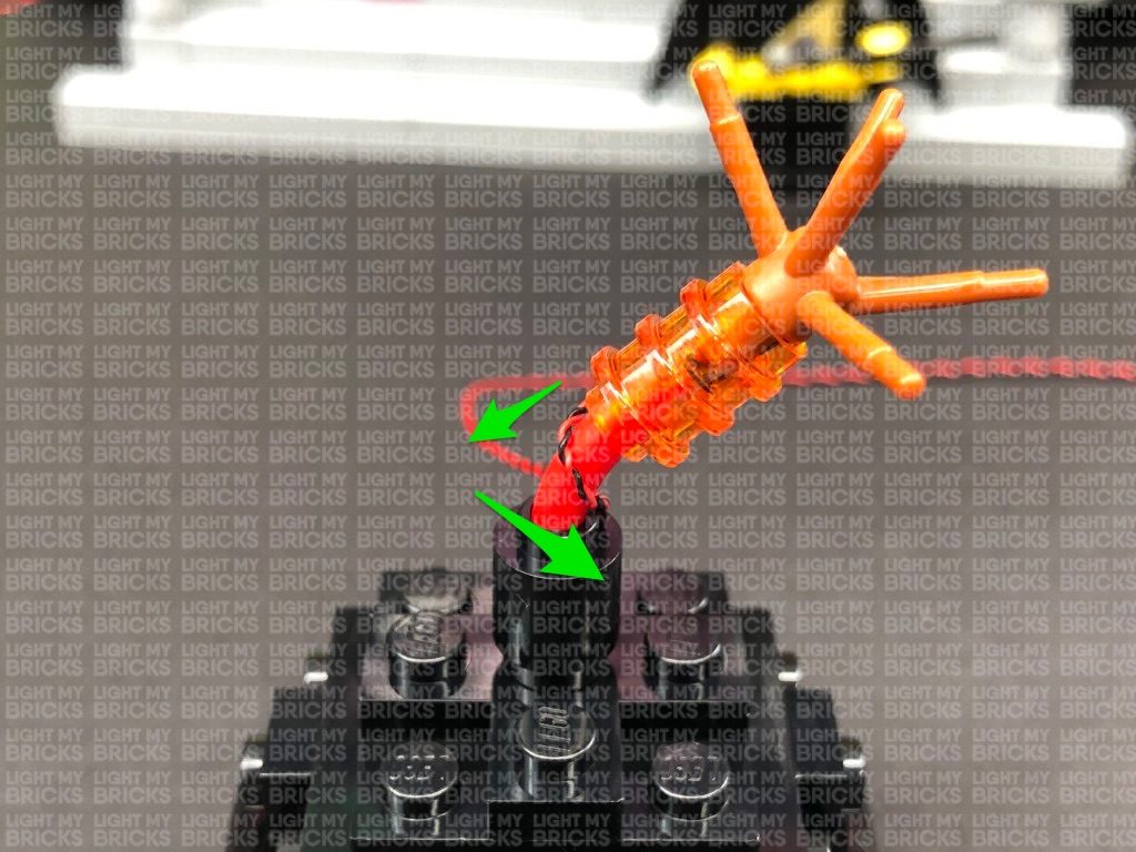
Take a White 30cm Bit Light and thread the connector end of the cable through the top of one of the trans orange round plates with open stud. Thread it
all the way through, then carefully bend the LED so that it sits flat against the edge of the stud.
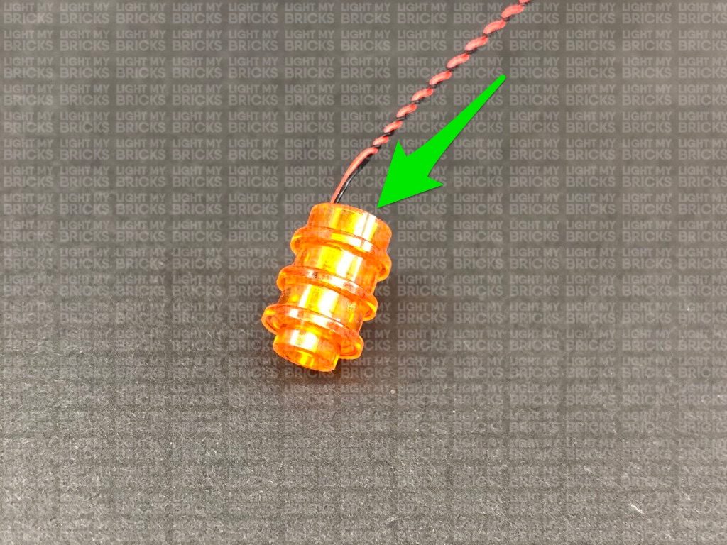
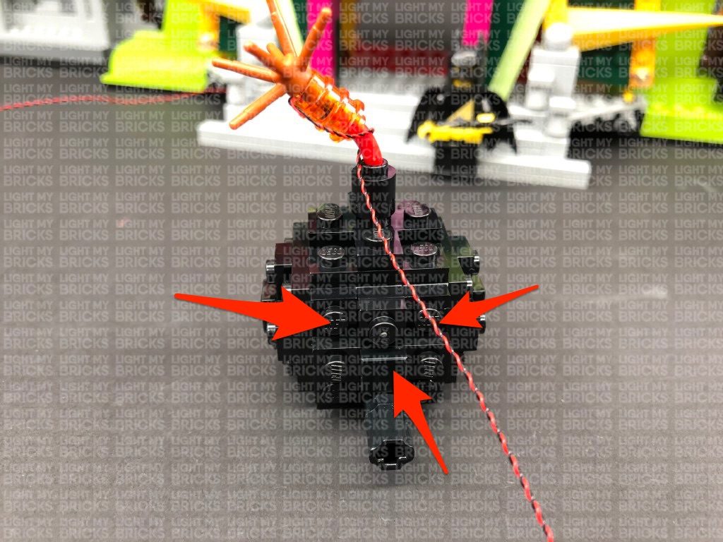
Reconnect a trans orange round plate with open stud on top, then connect the remaining trans orange round plate with open stud to the bottom.
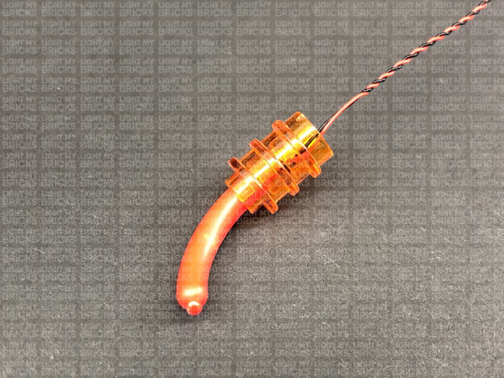
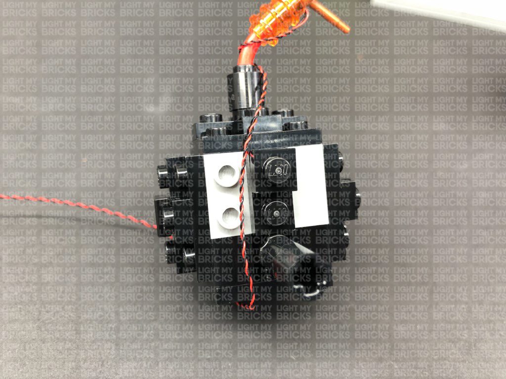
Reconnect the sausage piece to the bottom, then reconnect the branch piece to the top.

Reconnect this spark section to the bomb ensuring the cable is facing away from the spark (toward the right of the bomb) then twist the cable to the left
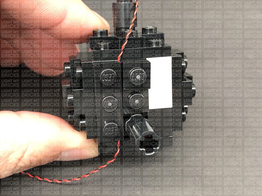
around the sausage piece. Remove the following pieces on the back of the bomb, then lay the cable all the way down before reconnecting the pieces over
the top of the cable.
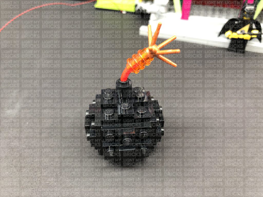
14.) Repeat the previous step to install White 30cm Bit Light to the right cherry bomb.

Reconnect this spark section to the bomb ensuring the cable is facing away from the spark (toward the left of the bomb) then twist the cable to the right
around the sausage piece. Remove the following pieces on the back of the bomb, then lay the cable all the way down before reconnecting the pieces over
the top of the cable.

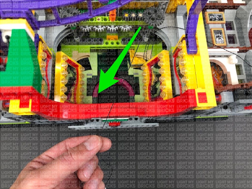
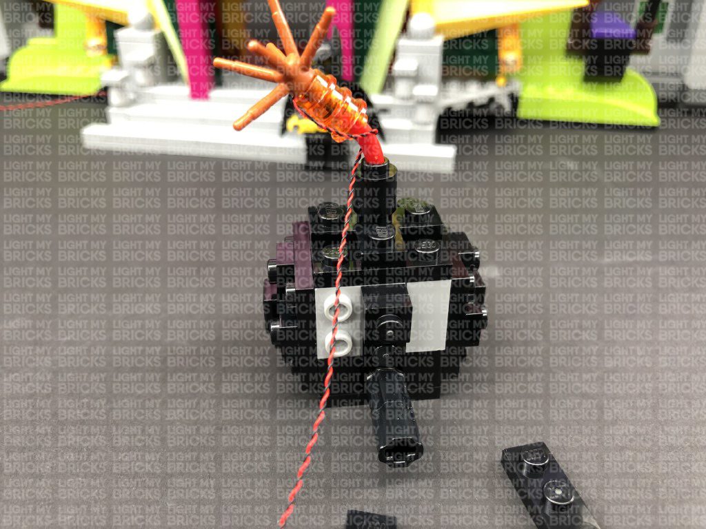
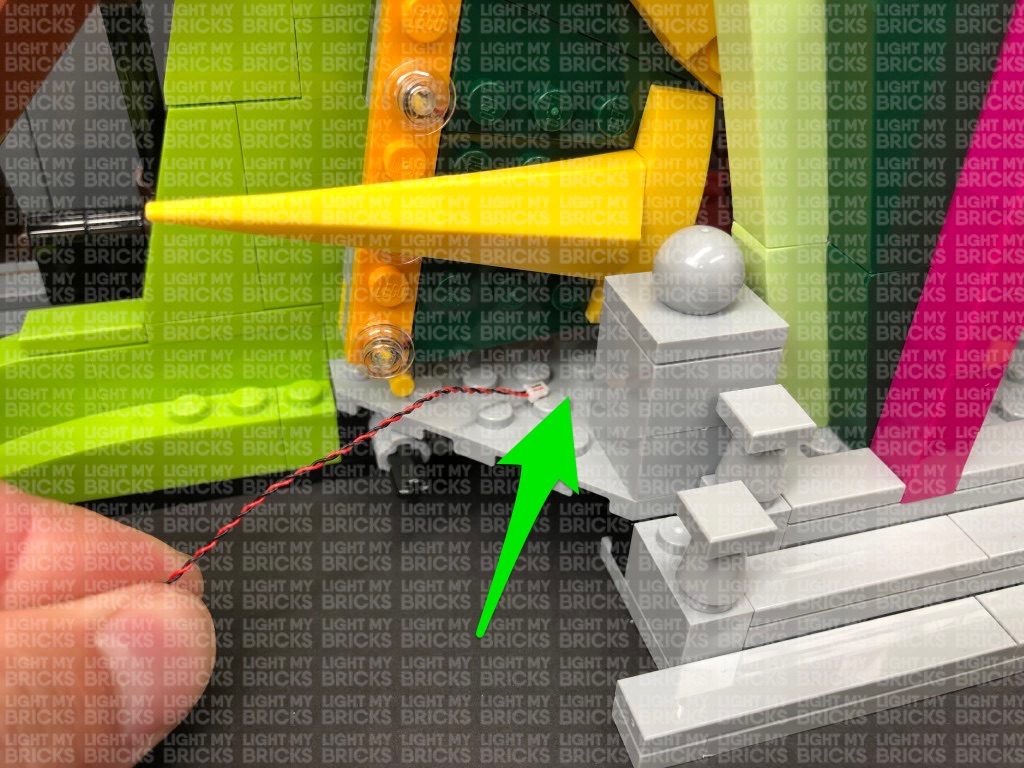
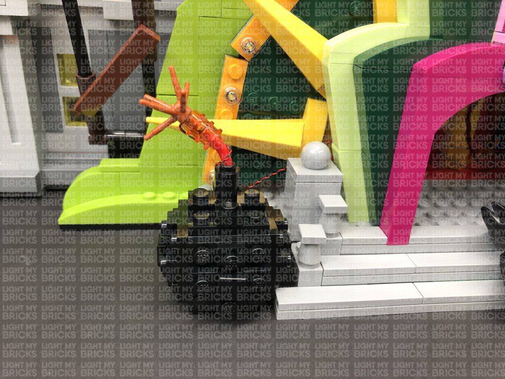
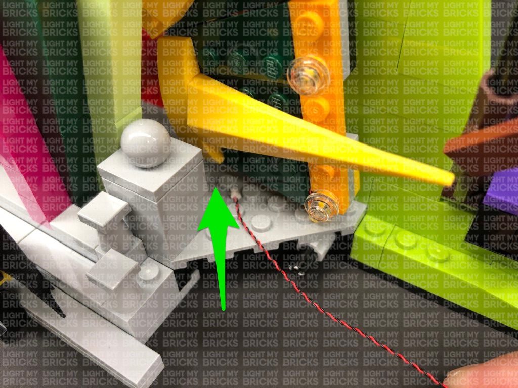
15.) Take both cherry bombs and thread their Bit Light cable all the way through the side of the entrance underneath the light sections before
reconnecting the bombs to the set.
Turn the set around to the back, then pull both cables from the cherry bombs all the way out. Connect each cable to the OUT ports on the Flicker Effects
Board.
/
