Page is loading ...

CPVC Fire Sprinkler Products
Installation
Instructions &
Technical Handbook


FEBRUARY 2021
Installation Instructions &
Technical Handbook
IH-1900
www.tyco-fire.com
1400 Pennbrook Parkway, Lansdale, PA 19446 | Telephone +1-215-362-0700
© 2021 Johnson Controls. All rights reserved. All specifications and other information shown were current as of docu-
ment revision date and are subject to change without notice.

1. GENERAL DESCRIPTION ...................................4
INTRODUCTION ...........................................4
Advantages ...............................................5
Training and Demonstration ................................5
Trademarks Appearing In This Manual ....................... 5
2. LISTINGS AND APPROVALS ................................7
LISTINGS/APPROVALS (WHERE TO USE) ..................... 7
Underwriters Laboratories Inc. (UL) and
Underwriters Laboratories Inc. (C-UL) For Use In Canada .......7
Concealed Installations (UL) ..............................7
Concealed Installations (C-UL) ............................8
Installation in Concrete (UL & C-UL) ........................8
Exposed Installation - General (UL & C-UL) .................10
Smooth, Flat, Horizontal, Fixed Ceilings -
Exposed Installations (UL & C-UL) ........................10
Unfinished Basements - Exposed Installations ..............14
Residential Dry Pipe Systems (UL) ........................16
Air Plenums (UL) ........................................17
Garage Installations (UL) ................................17
System Risers (UL) ......................................18
Underground Water Pressure Service (UL & C-UL) ..........20
Outdoor Installations ....................................23
Concealed Installations (FM) .............................23
Exposed Installations -
Smooth, Flat, Horizontal Ceilings (FM) .....................23
System Risers (FM) .....................................25
The Loss Prevention Council (LPCB) ......................25
Additional Approvals ......................................26
Ordinary Hazard Installations ..............................26
3. TECHNICAL DATA ........................................29
TYCO CPVC Specifications ................................29
Pipe ...................................................29
Fittings ................................................30
Solvent Cement ........................................30
Product Ratings and Capabilities ...........................30
Ambient Temperature and Heat Sources ...................30
Pressure Rating ........................................30
Friction Loss ...........................................31
Thermal Expansion – U.S. Units ...........................32
Thermal Expansion – Metric Units .........................34
Physical and Thermal Properties ...........................45
Permissible Bending Deflections ..........................45
Support and Hanger Requirements .........................50
Pipe Bracing with Standard Band Hanger ..................51
Hanger/Support Spacing ................................51
Vertical Restraint .......................................52
Sway Bracing Guidance for CPVC .........................54
TABLE OF CONTENTS

Chemical Compatibility ...................................55
Paint ...................................................55
4. INSTALLATION ...........................................58
Handling & Storage of TYCO CPVC ..........................58
Handling - Pipe and Fittings ..............................58
Storage - Pipe & Fittings ................................58
Handling - Solvent Cements ..............................59
Storage - Solvent Cements ...............................59
Solvent - Cement Spills ..................................59
Joining CPVC Pipe and Fittings with
One-Step Solvent Cement . . . . . . . . . . . . . . . . . . . . . . . . . . . . . . . . . 60
Estimating Cement Requirements .........................60
Cutting ................................................61
De-burring and Beveling .................................61
Solvent Cement Application ..............................61
Assembly ..............................................63
Set and Cure Times .....................................63
TFP-500 or TFP-600 Solvent Cement Cure Times ............64
System Acceptance Testing (Hydrostatic Pressure Test) .....65
Limited Pressurized Air or Nitrogen Testing Allowance .......65
Joining Pipe and Fittings in Adverse Conditions ..............66
In Cold Weather ........................................66
In Hot Weather .........................................67
Transition to Other Materials ............................... 67
Brass Threaded Connections .............................68
Sprinkler Installation in Rapid Seal Adapter (RSA) Fittings . . . .68
Gasket Replacement in Rapid Seal Adapter (RSA) Fittings . . . .69
Grooved Coupling Adapter Connections ...................70
Penetrating Fire Rated Walls & Partitions .................... 70
Freeze Protection ........................................ 71
Use of Dry Type Sprinklers ...............................71
Use and Cautions with Glycerin Antifreeze .................71
Batt Insulation Requirements and Suggestions .............72
Batt Insulation Installation Recommendations ..............73
Cut-in Procedure for System Modification and Repair . . . . . . . . . 73
5. Visit WWW.TYCO-FIRE.COM ............................... 76
6. APPENDIX A - PIPE FITTINGS . . . . . . . . . . . . . . . . . . . . . . . . . . . . . . 78
7. APPENDIX B - DO’S AND DON’TS ...........................99
8. IMPORTANT INFORMATION ..............................101
Important Information with Regards to Your TYCO CPVC Fire
Sprinkler System ....................................... 101
Notification to Jobsite Building Trades .....................102
TABLE OF CONTENTS

INTRODUCTION
This Installation Handbook refers to TYCO
CPVC Pipe and Fittings produced
by Johnson Controls. TYCO CPVC Pipe and Fittings are produced using
BLAZEMASTER CPVC compound. When reference to NFPA Standards is
made in this Installation Handbook, the current edition of the relevant code
is used. This Installation Handbook contains the criteria for installation
(including system design, handling, and storage) of BLAZEMASTER
CPVC piping systems in accordance with the applicable Listing/
Approval agencies. Additionally, this handbook contains general piping
practices and other installation suggestions that may not be required to
satisfy the applicable Listing/Approval agencies. To differentiate between
a requirement and a suggestion, use the following definitions:
SHALL or MUST – The use of the words “shall” or “must” indicates a
mandatory requirement of the Listings/Approvals.
SHOULD or MAY – The use of the words “should” or “may” indicates
a recommendation that is strongly advised, but not
required to meet the Listings/Approvals.
This handbook is intended as a supplement to basic, fundamental knowledge
relating to the installation and/or repair of CPVC fire sprinkler systems.
Before commencing installation, a user should understand this Installation
Handbook and confirm applicable National Fire Protection Association
(NFPA) standards, the National Building Code of Canada (as applicable), and
local approval and installation requirements for CPVC fire sprinkler systems.
NOTICE
The TYCO CPVC Pipe and Fittings described herein must be installed and
maintained in compliance with this Installation Handbook and with the
applicable standards of the National Fire Protection Association, in addition
to the standards of any authorities having jurisdiction. Failure to do so may
impair the performance of the TYCO CPVC Pipe and Fittings.
The owner is responsible for maintaining their fire protection system and
devices in proper operating condition. The installing contractor or product
manufacturer should be contacted with any questions.
It is the designer’s responsibility to select products suitable for the intended
service and to ensure that pressure ratings and performance data are not
exceeded. Material selection should be verified to be compatible for the
specific application. Designers and Installers must read and understand the
installation instructions in this handbook.
Never remove any piping component or modify any piping deficiencies
without first depressurizing and draining the system.
WARNING
Never use compressed air or nitrogen in lieu of or to replace the re-
quired hydrostatic system acceptance testing. Any pre-testing performed
with low pressure air or nitrogen should follow the recommendations on
Page 65. System failure when using high-pressure compressed air or ni-
trogen may result in property damage, serious injury, or death.
4
GENERAL DESCRIPTION

TRADEMARKS APPEARING IN THIS MANUAL
TYCO .......................registered trademark of Johnson Controls
HEAD SET . . . . . . . . . . . . . . . . . . .registered trademark of Johnson Controls
LFP Antifreeze . . . . . . . . . . registered trademark of Johnson Controls
BLAZEMASTER . . . . . . . . . . .registered trademark of The Lubrizol Corporation
CAULK AND WALK . . . . . . . .registered trademark of The Lubrizol Corporation
SOFFI-STEEL . . . . . . . . . . . . . . . . . . registered trademark of Grice Engineering
TEFLON . . . . . . . . . . . . . . . . . . . . . . . . . . . . . . . registered trademark of Dupont
OATEY . . . . . . . . . . . . . . . . . . . . . . . . . . . . . . . . . registered trademark of Oatey
GREAT WHITE . . . . . . . . . . . . . . . . . . . . . . . . . . . registered trademark of Oatey
CRISCO . . . . . . . . . . . . . . . . . . . . . . registered trademark of J.M. Smucker Co.
FBC SYSTEM COMPATIBLE PROGRAM . . . . . . . . . . . .registered trademark of
The Lubrizol Corporation
IMPORTANT
Refer to Technical Data Sheet TFP2300 for warnings pertaining to
regulatory and health information.
1
ADVANTAGES
TYCO CPVC Pipe and Fittings are designed specifically for fire sprinkler
systems and provide the following advantages over traditional sprinkler
piping systems:
• Increased hydraulic capabilities (C-Factor =150)
• No pre-cutting and expensive fabrication required
• Pipe, Slip Style Fittings and Rapid Seal Adapter (RSA) threaded
sprinkler connection fittings - NSF-pw listed for use in pressure rated
potable water piping systems
• Can easily be connected to other sprinkler piping systems
• Flexibility in the piping for greater ease of installation
• Resistant to rust, scale, and foreign contaminant build up
• Inexpensive tools required for installation
• Easily repaired or modified on site
• Easily transported and handled
• Resists sweating and condensation
TRAINING AND DEMONSTRATION
Johnson Controls strongly recommends that installers receive hands on
demonstration in the proper procedure(s) for installation of BLAZEMASTER
fire sprinkler systems. On-site demonstration in proper pipe preparation,
solvent cementing, proper handling of CPVC and installation instruction are
available from Johnson Controls at no charge. Upon completion of the TYCO
demonstration program, Johnson Controls will issue a completion card to
the persons successfully finishing the required subject matter. This card is
to be carried when working on TYCO CPVC systems. For information about
on-site demonstration, contact your local Johnson Controls Distribution
Center or your Johnson Controls sales representative.
5
GENERAL DESCRIPTION

6
GENERAL DESCRIPTION

LISTINGS/APPROVALS (WHERE TO USE)
For verification of Listings and Approvals, consult the current UL Fire
Protection Equipment Directory, C-UL Products Certified for Canada
Directory, Factory Mutual Research Approval Guide, or LPCB List of
Approved Fire Security Products and Services Guide.
Johnson Controls manufactures CPVC pipe and fittings using Lubrizol’s
BLAZEMASTER compound as a licensee of The Lubrizol Corporation.
UNDERWRITERS LABORATORIES INC. (UL) AND
UNDERWRITERS LABORATORIES INC. (C-UL) FOR USE IN CANADA
TYCO CPVC Pipe and Fittings are UL and C-UL Listed for use in:
• Light Hazard and residential occupancies as defined in the Standard
for Installation of Sprinkler Systems, NFPA 13
• Residential occupancies as defined in the Standard for the Installation
of Sprinkler Systems in Low-Rise Residential Occupancies up to Four
Stories in Height, NFPA 13R
• Residential occupancies as defined in the Standard for Installation of
Sprinkler Systems in One and Two Family Dwellings and Manufactured
Homes, NFPA 13D
• Air plenums, as defined by the Installation of Air Conditioning and
Ventilating Systems, NFPA 90A
• Underground Water Pressure Service, NFPA 24
• System risers in accordance with NFPA 13, 13R, and 13D
• See UL Fire Protection Equipment Directory, categories VIWT and HFYH.
• See C-UL Products Certified for Canada Directory, categories VIWT7
and HFYH7.
TYCO fire sprinkler systems shall be employed in wet-pipe systems only. (A
wet pipe system contains water or water and glycerin (anti-freeze solution)
and is connected to a water supply so that the water or water and glycerin
(anti-freeze solution) will discharge immediately when a sprinkler is opened.)
National Fire Protection Association Standards 13, 13R, 13D and NFPA
24, in addition to the standards of any other authorities having jurisdiction,
must be referenced and followed for design and installation requirements
in conjunction with this installation handbook.
Concealed Installations (UL)
• In accordance with the UL Listing, protection shall be provided for TYCO
CPVC Pipe and Fittings. The minimum protection shall consist of either
one layer of 3/8 in. (9,5 mm) thick gypsum wallboard, 1/2 in. (12,7 mm)
plywood soffits, or a suspended membrane ceiling with lay-in panels
or tiles having a weight of 0.35 pounds per sq ft (1,7 kg per sq m) when
installed with metallic grids. For residential occupancies defined in NFPA
13D and 13R, the minimum protection may consist of one layer of 1/2 in.
(12,7 mm) plywood.
Listed Quick Response, standard or extended coverage, 225°F
(107°C) maximum temperature rated sprinkler or Listed Residential 225°F
2
7
LISTINGS & APPROVALS

(107°C) maximum temperature rated sprinkler located in accordance with
its Listing may be used.
Solvent cement joints shall be made with TFP-500 or TFP-600 One Step
Solvent Cement.
Concealed Installations (C-UL)
• In accordance with the C-UL Listing, protection shall be provided for
TYCO CPVC Pipe and Fittings. The minimum protection shall consist
of either one layer of 9,5 mm thick gypsum wallboard, one layer of
13 mm plywood, or a suspended membrane ceiling with lay-in panels or
tiles classified with respect to surface burning characteristics having a
mass of not less than 1,7 kg/m
2
when installed with metallic grids. The
effectiveness of this protection can be impaired if penetrated by large
openings such as ventilation grills, exhaust fans connected to metal
ducts serving washrooms excepted. Where such penetration is present,
individual openings exceeding 0,03 m
2
but not exceeding 0,71 m
2
in area
must be located such that the distance from the edge of the opening to
the nearest sprinkler does not exceed 300 mm.
In these cases any Quick or Standard Response, 107°C maximum
temperature rated sprinkler or Listed Residential 107°C maximum
temperature rated sprinkler located in accordance with its Listing may
be used. TYCO CPVC Pipe and Fittings shall not be used where such
openings exceed 0.71 m
2
in area.
Solvent cement joints shall be made with TFP-500 or TFP-600 One Step
Solvent Cement.
Installation in Concrete (UL & C-UL)
TYCO CPVC Pipe and Fittings are acceptable for use embedded in concrete.
Direct contact with concrete does not have any adverse chemical effect
on BLAZEMASTER materials. The following installation practices shall be
followed.
• As the TYCO CPVC pipe is laid out it shall not come into contact with
sharp objects or edges, such as rocks, metal, or structural members.
Any open pipe ends shall be protected from debris or concrete getting
into the system.
• When laying out TYCO CPVC pipe it is best to use straight runs of pipe.
However, CPVC pipe is inherently ductile and it is possible for CPVC pipe
to be snaked when it is laid out. This can be useful in some installations
when some offset from a straight run can be helpful in avoiding various
construction obstacles. Straight runs of pipe will minimize any stress that
is exerted on the pipe. When the pipe is embedded in concrete there is not
opportunity to relieve any stress once the concrete is poured. Therefore,
it is important to layout the piping such that the stress is minimized from
the time of installation. (Refer to Pipe Deflection section for allowable
deflection.)
• Avoid the contact of TYCO CPVC Pipe and Fittings with construction
materials that are incompatible with CPVC. Verify the suitability of a
product for use with CPVC with the manufacturer of the chemical additive
to confirm chemical compatibility.
8
LISTINGS & APPROVALS

BLAZEMASTER CPVC pipe and fittings have been successfully
installed encased in concrete for many years. Lubrizol is unaware of any
problems that have been caused by chemical incompatibility between
BLAZEMASTER pipe and fittings and concrete or any chemicals that have
been added to concrete. Since new construction materials are regularly
introduced to the market, however, you may have questions regarding the
compatibility of the products you’re using. To help ensure a successful
installation, Lubrizol recommends contacting the manufacturer of the
chemical to confirm chemical compatibility.
• Steps must be taken to prevent the wire mesh or reinforcing bars from
causing any abrasion damage to the TYCO CPVC Pipe and Fittings (see
Handling and Storage section). This is mostly of concern prior to pouring
the concrete. TYCO CPVC Pipe and Fittings shall not be installed in
concrete that is to be post tensioned. The post tensioning process can
create excessive forces which can damage the TYCO CPVC piping system.
• When there are pipe joints that will be covered in concrete, the installation
shall be pressure tested prior to pouring the concrete. If there will not
be any joints covered by concrete, there is no need to pressure test the
system prior to pouring the concrete.
• Prior to the pouring of the concrete, the TYCO CPVC pipe shall be
intermittently secured to prevent movement during this process.
Nonabrasive, plastic fasteners are good choices for this application. When
hangers are used, most metal hangers designed for metal pipe are suitable
for TYCO CPVC pipe. Do not use undersized hangers. Hangers with
sufficient load bearing surface shall be selected based on pipe size (e.g.,
1 1/2 in. hangers for 1 1/2 in. pipe). The hanger shall not apply compressive
load or have rough or sharp edges that come into contact with the pipe.
• Care shall be taken so that the TYCO CPVC Pipe and Fittings are not
damaged by the tools and equipment used to pour and finish the concrete.
All standard methods of pouring concrete onto the ceiling construction
with concrete pumps or concrete containers followed by compaction with
vibrators can be used in combination with TYCO CPVC sprinkler systems.
TYCO CPVC Pipe and Fittings shall not come into contact with equipment
such as tampers and agitators.
• As the concrete is poured, assure that the pipe has not moved from its
intended positioning.
• Thermal expansion and contraction is not an issue for TYCO CPVC Pipe
and Fittings that are embedded in concrete. Those forces are relieved in
a manner that does not affect the pipe or fittings. However, expansion
and contraction shall be incorporated in the design of those sections of
pipe that are not embedded in concrete. Failure to adequately allow for
stress at these points may result in damage to the pipe where it enters
and exits the concrete.
NOTE: It is recommended that when transitioning from embedded to
not embedded in concrete that 6 in. of 1 in. compatible foam pipe insu-
lation be installed around the embedded pipe.
2
9
LISTINGS & APPROVALS

Exposed Installation - General (UL & C-UL)
In accordance with the UL and C-UL Listings, TYCO CPVC Pipe and Fittings
may be installed without protection (exposed), subject to the following
additional limitations:
Note: NFPA standards permit the omission of automatic sprinklers in ar-
eas such as small closets and bathrooms. Where sprinklers are not re-
quired, and when approved by the authority having jurisdiction, it is ac-
ceptable to install BLAZEMASTER products exposed in these areas.
Note: Where piping is required to be mounted directly to the ceiling/wall,
the use of listed hangers for thermoplastic sprinkler piping mounted di-
rectly to the ceiling/wall is permitted. The resulting clearance between
the pipe and the ceiling/wall as a function of using the listed hanger is
acceptable.
Smooth, Flat, Horizontal, Fixed Ceilings -
Exposed Installations (UL & C-UL)
• Standard Coverage Sprinklers
- Pendent Sprinklers shall be Listed, Quick Response, 170°F (77°C)
maximum temperature rated, sprinklers having deflectors installed
within 8 in. (203,2 mm) of the ceiling. The maximum distance between
sprinklers shall not exceed 15 ft (4,6 m). Piping shall be mounted directly
to the ceiling.
- Upright Sprinklers shall be Listed, Quick Response, 155°F (68°C)
maximum temperature rated, installed within 4 in. (101,6 mm) of the
ceiling. The maximum distance between sprinklers shall not exceed
15 ft (4,6 m). The maximum distance from the ceiling to the centerline of
the main run of pipe shall not exceed 7 1/2 in. (190,5 mm). The distance
from the centerline of the sprinkler to the closest hanger shall be 3 in.
(76,2 mm).
- Horizontal Sidewall Sprinklers shall be Listed, Quick Response,
200°F (93°C) maximum temperature rated, having deflectors within
12 in. (305,0 mm) of the ceiling and within 6 in. (152,4 mm) of the side
wall. The maximum distance between sprinklers shall not exceed 14 ft
(4,3 m). Piping shall be mounted directly to the side wall.
- Solvent cement joints shall be made with TFP-500 or TFP-600 One Step
Solvent Cement.
• Extended Coverage Sprinklers
- Pendent Sprinklers shall be Listed, Quick Response, 155°F (68°C)
maximum temperature rated, having deflectors installed within 8 in. (203,2
mm) of the ceiling. The maximum distance between sprinklers shall not
exceed 20 ft (6,1 m) with an application density of at least 0.1 gpm/sq ft
(4,1 mm/min). Piping shall be mounted directly to the ceiling.
- Horizontal Sidewall Sprinklers shall be Listed, Quick Response,
165°F (74°C) maximum temperature rated, having deflectors within
12 in. (305,0 mm) of the ceiling and within 6 in. (152,4 mm) of the side
wall. The maximum lateral distance between sprinklers shall not exceed
18 ft (5,5 m) with an application density of at least 0.1 gpm/ft
2
(4,1 mm/
min). Piping shall be mounted directly to the side wall.
10
LISTINGS & APPROVALS

- Horizontal Sidewall Sprinklers shall be Listed, Quick Response,
175°F (79°C) maximum temperature rated, having deflectors within
12 in. (305,0 mm) of the ceiling and within 6 in. (152,4 mm) of the side
wall. The maximum lateral distance between sprinklers shall not exceed
16 ft (4,9 m) with an application density of at least 0.1 gpm/ft
2
(4,1 mm/
min). Piping shall be mounted directly to the side wall.
- When using fittings 1 1/2 in. (DN40) and larger only Schedule 80 fittings
may be used.
- Solvent cement joints shall be made with TFP-500 or TFP-600 One Step
Solvent Cement.
• Residential Sprinklers
- Pendent Sprinklers when the maximum lateral distance between
sprinklers is 15 ft (4,6 m) or less. Sprinklers shall be Listed 170°F (77°C)
maximum temperature rated, having deflectors located in accordance
with their Listing and not exceeding 8 in. (203,2 mm) from ceiling. The
demand for the sprinklers shall be the minimum flow rates indicated in
individual listing. Piping shall be mounted directly to the ceiling.
- Pendent Sprinklers when the maximum lateral distance between sprinklers
exceeds 15 ft (4,6 m) but does not exceed 20 ft (6,1 m). Sprinklers shall
be Listed 155°F (68°C) maximum temperature rated, having deflectors
located in accordance with their Listing and not exceeding 8 in.
(203,2 mm) from ceiling. The demand for the sprinklers shall be the greater
of either the minimum flow rates indicated in individual listing or calculated
based on delivering a minimum of 0.1 gpm/sq ft (4,1 mm/min) over the
design area in accordance with the provisions of NFPA 13:(2007) Section
11.3.1.2. Piping shall be mounted directly to the ceiling.
- Horizontal Sidewall Sprinklers when the maximum lateral distance
between sprinklers is 14 ft (4,3 m) or less. Sprinklers shall be Listed
200°F (93°C) maximum temperature rated having deflectors located in
accordance with their Listing. The demand for the sprinklers shall be the
minimum flow rates indicated in individual listing. Piping shall be mounted
directly to the side wall.
- Horizontal Sidewall Sprinklers when the maximum lateral distance
between sprinklers exceeds 14 ft (4,3 m) but does not exceed 18 ft
(5,5 m). Sprinklers shall be Listed 165°F (74°C) maximum temperature
rated having deflectors 12 in. (305,0 mm) from ceiling and within 6 in.
(152,4 mm) of the wall. The demand for the sprinklers shall be the greater
of the minimum flow rates indicated in individual listing or calculated
based on delivering a minimum of 0.1 gpm/sq ft (4,1 mm/min) over the
design area in accordance with the provisions of NFPA 13:(2007) Section
11.3.1.2. The maximum sprinkler area of coverage shall not exceed 18 ft
x 18 ft (5,5 m x 5,5 m). Piping shall be mounted directly to the side wall.
- When applying criteria having a minimum 0.1 gpm/sq ft (4,1 mm/min),
Schedule 80 fittings must be used when sizes are 1 1/2 in. (DN40) and
larger.
- Solvent cement joints shall be made with TFP-500 or TFP-600 One Step
Solvent Cement.
2
11
LISTINGS & APPROVALS

8'-0"
(2,4 m)
TO WALL OR
BLOCKING
(12,2 m) MAX.
TO CENTER
OF RISER
(304,8 mm)
TO PIPE
(609,6 mm)
FROM WALL
TO EDGE OF
(38,1 mm)
1" MIN. TO
2" MAX.
RISER
BRANCH
MAIN
(44,5 mm)
MAX.
MAX.
2x16
MAX.
16'-0"
(4,9 m)
MAX.
16'-0"
(4,9 m)
MAX.
8'-0"
(2,4 m)
MAX.
1-3/4"
12" MAX.
2'-0" MAX.
1-1/2" MAX.
40'-0"
RISER
SUPPORT
24"
(609,6 mm)
CENTERS
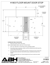
Figure 1 - Unfinished Basement, Solid Wood Joists, Center Wall
Riser with Center Room Main
MAIN
8'-0"
(2,4 m)
BRANCH
MAX.
16'-0"
(4,9 m)
MAX.
16'-0"
(4,9 m)
MAX.
8'-0"
(2,4 m)
MAX.
(44,5 mm)
MAX.
1-3/4"
FROM WALL
TO EDGE OF
(38,1 mm)
1-1/2" MAX.
RISER
24"
(609,6 mm)
CENTERS
1" MIN. TO
2" MAX.
RISER
TO WALL OR
BLOCKING
(12,2 m) MAX.
40'-0"
MAX. TO CENTER
12" (304,8 mm)
OF RISER
MAX.
2x16
TO PIPE
(609,6 mm)
2'-0" MAX.
SUPPORT
Figure 2 - Unfinished Basement, Solid Wood Joists, Center Wall
Riser with Main at Wall
12
LISTINGS & APPROVALS

Branches
Supported with
Blocking
Branches
Supported with
Hangers
DEPTH
MAX.
1/2 JOIST
1-3/4"
MAX.
DEPTH
MAX.
1/2 JOIST
1-3/4"
MAX.
Figure 5 - Unfinished Basement, Branch Line Support
MAIN
FROM WALL TO EDGE
OF RISER
1-1/2" (38,1 mm) MAX.
1" MIN. TO
2" MAX.
RISER
BRANCH
16'-0"
(4,9 m)
MAX.
16'-0"
(4,9 m)
MAX.
8'-0"
(2,4 m)
MAX.
(44,5 mm)
MAX.
1-3/4"
24"
(609,6 mm)
CENTERS
MAX.
2x16
8'-0"
(2,4 m)
MAX.
MAX. TO CENTER
12" (304,8 mm)
OF RISER
TO WALL OR
BLOCKING
(12,2 m) MAX.
40'-0"
MAX. TO PIPE
2'-0" (609,6 mm)
SUPPORT
Figure 3 - Unfinished Basement, Solid Wood Joists, Riser in Corner
24" MAX.
CENTERS
CEILINGBLOCKING
BLOCKING
TO FULL DEPTH
OF JOIST
JOIST
2" x 16" MAX.
Figure 4 - Unfinished Basement, Solid Wood Joists, Blocking
2
13
LISTINGS & APPROVALS

Unfinished Basements - Exposed Installations
Solid and Composite Wood Joists (UL and C-UL)
TYCO CPVC Pipe and Fittings may be installed without protection (exposed)
in unfinished basements in accordance with NFPA 13D when subject to
the following additional limitations:
• The ceiling shall be horizontal and constructed utilizing solid wood joists
or composite wood joists with a nominal depth of 16 in. (406,4 mm) or
less on maximum 24 in. (609,6 mm) centers.
• The distance from the floor to the bottom of the joists shall be between
7 ft and 10 ft (2,1 m and 3,0 m).
• Listed residential pendent sprinklers with a maximum temperature rating
of 155°F (68°C) and a minimum K-factor of 4.9 are to be used for this type
of installation. The maximum sprinkler spacing shall not exceed 16 ft
(4,9 m). Lesser areas are also permitted. The system is to be designed
based upon the Listed flows for the sprinkler selected except that the flow
for a single sprinkler or for multiple sprinklers flowing is to be not less than
13 gpm (49,2 lpm) per sprinkler. The sprinklers are to be installed with their
deflectors a maximum of 1 3/4 in. below the bottom of the solid wood or
composite wood joists in anticipation of future installation of a finished
ceiling. (Refer to NFPA 13D, Section 8.2.4, 2016 Edition.)
• Schedule 80 fittings in the 1 1/2 in. and larger sizes shall be used.
• All solvent cement joints shall be made with One Step Solvent Cement
(TFP-500 or TFP-600).
• The maximum length along the joist shall not exceed 40 ft (12,2 m).
When the length exceeds 40 ft (12,2 m), blocking shall be utilized.
The blocking shall be constructed of minimum 1/2 in. (12,7 mm) plywood,
minimum 3/8 in. (9,5 mm) gypsum wallboard or batt insulation with a
minimum thickness of 3 1/2 in. (89 mm). These blocking materials shall
be the full depth of the joists. When batt insulation is used as blocking,
it must be a single piece of insulation. The insulation must be secured in
place with metal wire netting which must encase the insulation on both of
the exposed sides. The metal wire netting is required to hold the insulation
in place and prevent it from being dislodged or repositioned over time.
It is acceptable for items such as piping, wires, ducts, etc. to penetrate
the blocking. The gap between the item penetrating the blocking and the
blocking should be minimized. For installations where the gap exceeds
1/4 in. (6,4 mm), the gap shall be filled with insulation, caulking, or other
suitable material.
• When installing TYCO BlazeMaster® CPVC pipe and fittings perpendicular
to the joists:
- System mains installed below the joists shall use listed support devices
for thermoplastic sprinkler piping or other listed support devices which
mount the piping directly to the bottom of the joists.
- System mains and branch lines installed through the joists using holes,
for support, shall be at or below the center of the depth of the joist. The
holes should be oversized to allow for movement and located to not
impair the structural integrity of the joists.
14
LISTINGS & APPROVALS

CAUTION
When drilling holes in the joists, the structural integrity must be main-
tained. Consult the Authority Having Jurisdiction (AHJ) or building code
for requirements.
• When installing TYCO BlazeMaster® CPVC pipe and fittings parallel to
the joists:
- System mains and branch lines shall be installed in the cavity below the
bottom of the ceiling and above the bottom of the joist. The pipe and
fittings shall be located at or below the center of the depth of the joist. The
pipe shall be installed utilizing listed support devices for thermoplastic
sprinkler piping or other listed support devices which mount the piping
directly to nominal 2 in. wood blocking or listed support devices for
thermoplastic sprinkler piping which offset the pipe a nominal distance
of 1 1/2 in. from the joists.
NOTE:
Use of TYCO CPVC Pipe and Fittings is limited to basements where the
quantity and combustibility of contents is low and fires with relatively
low rates of heat release are expected. For additional information re-
garding the assembly and installation of TYCO CPVC Pipe and Fittings
refer to the manufacturer’s installation instructions.
• The instructions shown here for Unfinished Basements with Exposed Solid
Wood or Composite Wood Joists require the use of Schedule 80 fittings
when sizes are 1 1/2 in. (DN40) and larger.
Use of TYCO CPVC Pipe and Fittings is limited to basements where the
quantity and combustibility of contents is low and fires with relatively low
rates of heat release are expected.
Combustible Concealed Spaces (UL)
TYCO CPVC Pipe and Fittings are not approved for installation in combustible
concealed spaces requiring sprinklers, as referenced in NFPA 13 unless
protected by sprinklers specifically Listed for this application. Although NFPA
13R and 13D permit the omission of sprinklers from combustible concealed
spaces, TYCO CPVC Pipe and Fittings can be installed in these areas when
protecting residential occupancies according to these standards.
For installations where sprinkler pipe runs through an attic space that requires
sprinklers per NFPA, CPVC piping shall be protected in order to meet the
requirements of its UL and C-UL Listings. Additionally, the authority having
jurisdiction shall be consulted prior to any installation of CPVC in attic spaces
requiring sprinklers. Protection methods and requirements may vary by
jurisdiction and are subject to interpretation.
• Special Use Sprinklers - TYCO Specific Application Attic Sprinklers
- Product Description - In accordance with the UL Listing, the TYCO
Specific Application Sprinklers for Protecting Attics are designed to
provide protection of specific light hazard combustible, as well as
noncombustible, attic spaces requiring sprinkler protection. The Specific
Application Sprinklers for Protecting Attics allow for the use of TYCO
CPVC Pipe and Fittings within the attic space and to supply the wet
2
15
LISTINGS & APPROVALS

system sprinklers below the ceiling provided the attic space is protected
with Specific Application Sprinklers for Protecting Attics.
- Installation Requirements - When using the Specific Application Sprinklers
for Protecting Attics, reference Technical Data Sheet TFP610.
• Special Use Sprinklers - TYCO Specific Application Model CC1, CC2, and
CC3 Combustible Concealed Space Sprinklers
- Product Description - In accordance with the UL Listing, the TYCO
Specific Application Model CC1, CC2, and CC3 Combustible Concealed
Space Sprinklers are specific application sprinklers designed to
provide protection of specific light hazard combustible, as well as
noncombustible, concealed spaces requiring sprinkler protection. The
Model CC1, CC2, and CC3 Sprinklers in some cases allow for the use
of TYCO CPVC Pipe and Fittings within concealed spaces requiring
automatic sprinkler protection.
- Installation Requirements - When using the Model CC1, CC2, and CC3
Sprinklers, reference Technical Data Sheet TFP630, TFP632, and TFP633
respectively.
Residential Dry Pipe Systems (UL)
In accordance with the Underwriters Laboratories Inc. (UL) Listing, TYCO
CPVC Fire Sprinkler Pipe and Fittings made with BLAZEMASTER compound
may be installed in Dry Pipe Systems for Residential Occupancies when
subject to the additional limitations listed in this section.
• Acceptable Residential Occupancies are defined as follows:
- Concealed (protected) installations in residential sprinkler systems for
one- and two- family dwellings and manufactured homes per NFPA 13D.
- Residential sprinkler systems for residential occupancies up to and
including four stories in height per NFPA 13R.
- Residential portions of any occupancy per NFPA 13 where calculations
for Dry Pipe System water delivery are based on the hazard shown in
Table A using a calculation program listed by a nationally recognized
laboratory or obtained where the system design specifies that water is
delivered to the system test connection in not more than 15 seconds for
Residential Occupancies, starting at normal air pressure on the system.
• Residential sprinklers used in conjunction with TYCO CPVC Fire Sprinkler
Pipe and Fittings in Dry Pipe Systems shall be specifically listed for such
use.
• The TYCO CPVC Sprinkler Head Adapter Tee (P/N 80259) is to be used with
dry-type residential pendent sprinklers in dry pipe system installations.
• Dry Pipe Systems in areas subject to freezing shall be pitched at least
1/4 in. or 1/2 in. per 10 ft (2 mm/m) in accordance with the appropriate
NFPA standard being utilized.
• Upon completion of the assembly and cure, the system shall by
hydrostatically tested in accordance with the procedures described in
the CPVC Installation Handbook (IH-1900).
• TYCO CPVC Fire Sprinkler pipe and fittings used in Dry Pipe Systems may
16
LISTINGS & APPROVALS

not be used in combination with other thermoplastic piping systems unless
specifically listed for use in Dry Pipe Systems. Combining with steel or
copper piping systems is permitted, where applicable.
• The pipe and fittings shall be protected (concealed) in accordance with
the specifications outlined in the CPVC Installation Handbook (IH-1900).
• Exposed pipe and fittings have not been evaluated.
• Minimum use temperature shall be -20°F (-29°C).
• 3/4 in. to 3 in. pipe and fittings are listed for these applications and are
to be assembled with TFP-500 or TFP-600 One Step Solvent Cement.
• In-service system Air Pressure shall be maintained at a maximum of
15 psi (1 bar).
• Pipe friction loss shall be calculated in accordance with the Hazen-Williams
formula using a C value of 150.
• Air supply to the TYCO CPVC Pipe and Fittings shall be free of oil and oil
vapor. Automatic air compressors shall be of an oil-less type or the air
shall be treated to assure oil or oil vapor is not introduced into the piping.
Table A
Residential Dry Pipe System
Water Delivery
Hazard Residential Light
Number of
Most Remote Sprinklers
Initially Open
1 1
Maximum Time of Water
Delivery
15 Seconds 60 seconds
Air Plenums (UL)
TYCO CPVC Pipe and Fittings are UL Listed for use in air plenums. TYCO
CPVC Pipe and Fittings comply with UL1887 combustibility requirements
for thermoplastic sprinkler pipe as described in the Standard for Installation
of Air Conditioning and Ventilating Systems, NFPA 90A, and various model
mechanical codes. TYCO CPVC Pipe and Fittings may be installed in the
plenum adjacent to, but not over, an opening in the ceiling such as ventilation
grills. Return Air Plenum installations may only be made with UL Listed TYCO
CPVC Pipe and Fittings and require the use of Schedule 80 fittings when
sizes are 1 1/2 in. (DN40) and larger.
Garage Installations (UL)
Garage Installation Specifications shall only apply for the installation of
UL Listed TYCO CPVC Pipe and Fittings in garages requiring sprinkler
protection per NFPA 13D and NFPA 13R. These Standards are defined in
NFPA codes entitled “One and Two Family Dwellings and Mobile Homes” and
in “Residential Occupancies up to Four Stories in Height”. As referenced in
NFPA 13D:(2007) Section 8.6.4, “Sprinklers are not required in garages, open
attached porches, carports or similar structures.” The installation of TYCO
CPVC Pipe and Fittings for use in garages requiring sprinkler protection per
NFPA 13R is only applicable to the UL Listing of this product.
2
17
LISTINGS & APPROVALS

Requirements for Pipe, Fittings, Solvent Cement Systems, System Design,
Installation, Freeze Protection, and Penetrating Fire Related Walls and
Partitions are covered in this Installation Handbook. Read these sections
carefully prior to designing or installing TYCO CPVC Pipe and Fittings for
garage installations.
• Installation Requirements
- Protection: TYCO CPVC Pipe and Fittings shall be installed concealed
behind protection consisting of a minimum of one layer of 3/8 in.
(9,5 mm) thick gypsum wallboard or 1/2 in. (13 mm) thick plywood.
- Sprinkler Requirements: UL Listed, pendent or sidewall sprinklers
with a 225°F (107°C) maximum temperature rating shall be utilized. All
sprinklers shall be installed per the manufacturer’s published installation
instructions.
- Installation Standard: The Listing for Garage Installations shall pertain
to those occupancies defined by NFPA 13R.
System Risers (UL)
In accordance with the UL Listing, TYCO CPVC Pipe and Fittings may be
used as system risers in accordance with NFPA 13, 13D, and 13R when
subject to the following additional limitations:
1. When installed protected (concealed) in accordance with NFPA 13, 13D,
and 13R, the minimum protection shall consist of either one layer of
3/8 in. (9,5 mm) thick gypsum wallboard or 1/2 in. (12,7 mm) thick plywood.
2. When installed without protection (exposed) in accordance with
NFPA 13D and 13R, the following limitations shall apply:
- The riser shall be installed below a smooth, flat, horizontal ceiling
construction. A Listed residential pendent sprinkler is to be installed
with its deflector at the distance from the ceiling specified in the
sprinkler Listing.
or
The riser shall be installed below a horizontal unfinished basement ceiling
(in accordance with NFPA 13D) constructed utilizing solid wood joists
or composite wood joists with a nominal depth of 16 in. (406,4 mm) or
less on maximum 24 in. (609,6 mm) centers. A Listed residential pendent
sprinkler is to be installed with its deflector a maximum of 1 3/4 in.
(44,5 mm) below the bottom of the solid wood or composite wood joist
in anticipation of the future installation of a finished ceiling.
- The Listed residential pendent sprinkler is to have 155°F (68°C) maximum
temperature rating and a minimum K-factor of 4.9, and is to be installed
at a maximum horizontal distance of 12 in. (305,0 mm) from the centerline
of the riser. The system is to be designed based upon the Listed flows
for the sprinkler selected except that the flow for a single sprinkler or
multiple sprinklers shall not be less than 13 gpm (49,2 lpm) per sprinkler.
- The riser shall be supported vertically within 2 ft (610 mm) of the ceiling
or bottom of the joist.
- The minimum riser diameter shall be 1 in. (DN25) and the maximum riser
diameter shall be 2 in. (DN50).
18
LISTINGS & APPROVALS
/