Page is loading ...

RefeRence figuRes aRe on backside
c o n s u l t m p d 93756 f o r c o m p l e t e w a t e r h e a t e r
i n s t a l l a t i o n , o p e r a t i o n a n d m a i n t e n a n c e i n s t r u c t i o n s
m warning
fire or explosion
• Shut off gas supply at LP container before disconnecting a gas line.
1. Shut off LP gas.
m warning
scalding injury
• Water in tank must be cool before working on the water heater or
before replacement of tank.
2. Open hot water faucets and allow water to run until cool.
m warning
electrical shock injury/electrocution
• Power source must be disconnected before servicing of water
heater.
• Label all wires before disconnecting when servicing.
• Verify proper operation after servicing.
3. Shut off electric power at breaker box.
4. Shut off water supply if hooked up to outside source. Turn off water
pump in coach.
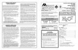
5. Remove drain plug ➀/➁-B and snap open pressure-temperature relief
valve
➀/➁
-F or open faucets in coach. Allow water to drain until it
stops flowing from the drain plug.
6. Disconnect LP gas line from 45° elbow ➀/➁-C.
7. Disconnect hot and cold water connections at back of water heater.
8. Remove burner assembly and other components, as listed:
n o t e : Use of proper thermostat and relief valve wrenches prevent damage
to components.
p i l o t m o d e l s : pilot assembly ➀-G and main burner ➀-H together,
carefully remove thermostat ➀-E, pressure-temperature relief valve
➀-F, flue box ➀-A and pilot relighter board ➀-I.
d i r e c t s p a r k i g n i t i o n m o d e l s : carefully remove main burner ➁-H, pressure
temperature relief valve ➁-F, flue box ➁-A and electrode ➁-K.
a. shut off 12 volt power at circuit breaker (fuse box).
b. disconnect brown and red wires from thermostat and ECO ➁-J.
c. remove black rubber pad, thermostat and ECO ➁-J.
9. Remove screws around flanges ➀/➁-D of combustion pan on outside
of water heater.
10. Using a wide bladed screwdriver or putty knife, loosen flanges from
side of coach by breaking the caulking seal.
11. Pull the water heater out of the coach.
d i r e c t s p a r k i g n i t i o n m o d e l s : Pull unit partially out of coach and
disconnect wires behind combustion pan flange ➁-D.
n o t e : Mark wires so they can be properly reconnected.
12.
Remove elbows or tees from water connections at back of water heater.
13. Pry up on metal grommets around large combustion tubes and cut-
off with cut-off blade and grinder. Separate tank from combustion
pan.
14. Install foam seal around drain valve and thermostat couplings on
new tank.
15. Insert tank into combustion pan. Place large gaskets around large
16. Replace all water fittings.
17. Heating elements in c o m b i n a t i o n g a s /e l e c t r i c m o d e l s :
scRew-in Heating element - 4 & 6 g a l l o n m o d e l
a. Disconnect black wire from the ON/OFF switch ➂-F to the black
power supply wire and the white wire from the element ➂-C to
the white neutral supply wire.
b.
Replacement tank is equipped with all 110VAC components
attached.
c. Attach black power source wire to the black wire of the ON/OFF
switch ➂-F and the white wire from the element ➂-C to the white
neutral supply wire. Go to step 18.
scRew-in Heating element - 10 g a l l o n m o d e l
a. Remove the cover ➃-A, insulation and cardboard protector ➃-D.
b. Remove white wire from element ➃-C, black wire from element
➃-C to ECO ➃-B, black wire from ECO ➃-B to thermostat ➃-E,
black wire from thermostat ➃-E to
o n /o f f s w i t c h ➃-F and green
ground wire from ground screw.
c. Unscrew element ➃-C from tank and remove gasket from flange.
d. Remove thermostat ➃-E and ECO ➃-B.
e. On new tank, install thermostat ➃-E and ECO ➃-B.
f. Install element gasket on flange, screw element ➃-C into new tank.
g. Re-attach green ground wire to ground screw, black wire from
thermostat ➃-E to o n /o f f s w i t c h , black wire from ECO ➃-B to
thermostat, black wire from element ➃-C to ECO ➃-B and white
wire to element ➃-C.
h. Replace cardboard protector ➃-D, insulation and the cover ➃-A.
Go to step 18.
bolt-in Heating element - a l l m o d e l s
a. Disconnect black wire from the o n /o f f s w i t c h ➄-A to the black
power supply wire and the white wire from the thermostat ➄-B
to the white neutral supply wire.
b. Replacement tank is equipped with all 110VAC components
attached.
c. Attach black power source wire to the black wire of the o n /o f f
s w i t c h
➄-A and the white wire from the element ➄-C to the white
neutral supply wire.
18. Insert water heater back into coach opening.
d i r e c t s p a r k i g n i t i o n m o d e l s : partially insert unit into coach and reconnect
wire as follows:
• brown wire to 12 volt positive (+)
• green wire to 12 volt negative (-)
• blue wire to non-ignition light
m caution
product damage
• 12 volt power must be off while reconnecting wires.
• Do not pinch wires when pushing unit into coach.
Put caulking around flanges and push against coach skin. Replace
all screws around flange securing unit to the coach. Fill any gaps
around the flanges with caulk to prevent rain water leaks.
19. Reassembly of water heater components.
a. p i l o t m o d e l s : using pipe compound on all threads, carefully screw
drain plug, relief valve and thermostat into tank and tighten
to original position. Replace flue box, main burner and pilot
assembly by reversing step 8.
tank Replacement
4-6-10 gallon lp Models
l i t e r a t u r e n u m b e r
mpd 91423
combustion tubes, then place metal retainer rings over tubes and tap
down until pressed firmly against back of combustion pan. Place
adhesive backed seal around relief valve coupling.
Revision A
, 10/22/18
DOMETIC CORPORATION
1120 North Main Street, Elkhart, IN 46514
Please Visit: WWW.DOMETIC.COM

C
A
F
D
C
PILOT MODEL -
SPARK IGNITION MODEL -
B
Back of 6 gallon unit
C
1
2
3
4
H
G
E
A
D
C
B
E
F
H
G
A
A
I
D
F
B
E
F
D
B
E
5
Back of 6 and 10 gallon unit
B
Screw-in heating element
Back of 10 gallon unit
Screw-in heating element
Bolt-in heating element
A
J
K
C
b. For d i r e c t s p a r k i g n i t i o n m o d e l s : Using pipe compound on all threads
carefully screw drain plug and relief valve into tank. Replace flue
box, main burner, electrode assembly and circuit board. Replace
thermostat and ECO by reversing steps 8-b and 8-c.
m caution
product damage
• Do not over-tighten pilot assembly’s thermocouple lead in control.
Tighten 1/4 turn beyond finger tight.
20. Reconnect water connections. Make sure inlet and outlet
connections are to correct fittings, and are leak proof. If a
winterizing bypass kit is utilized, ensure levers are in proper position.
m warning
death, explosion, fire or
carbon monoxide poisoning
• LP gas is extremely flammable. Test all fittings for gas leaks prior
to operation.
• DO NOT use matches, candles or other sources of ignition when
checking for gas leaks.
21. Hook up gas line connections. Turn on LP gas at bottles and
immediately check all gas connections with leak detection solution.
If bubbles are detected, turn off gas, retighten all connections and
repeat this procedure. Leaks are very dangerous. Double check all
connections.
m caution
product failure
• Do not operate water heater without water in tank.
22. Turn on water supply and water pump. Open hot water faucets until
a steady stream of water flows.
23. On c o m b i n a t i o n g a s /e l e c t r i c water heater units, reconnect electric power.
24. Follow instructions in IOM for lighting and operating the water
heater.
/


