
Page 36 Mast Series - Service & Parts Manual
May 2021Section 11 - Control System
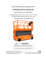
Fault Codes
Fault Codes, when present, appear on the LED Indicator at the Upper Controls station and on the
LED Screen at the Lower Controls station.
Art_5592
Lower Controls
LED Indicator
Upper Controls
LED Indicator

Page 37 Mast Series - Service & Parts Manual
May 2021Section 11 - Control System
Error Indicator Readout
Art_5533
If the LED diagnostic readout displays an error code, such as LL, push in and turn
the red Emergency Stop button to reset the system.
Fault Description Models Solutions
01/10 System Initialization Fault All Models Check ECU
02/20
System Communication
Fault
All Models
Check platform control box, check wiring to
platform connector, check ECU, check battery
voltage, check relay in lower cabinet
Micro26® Check height sensor, check pressure sensor
03 Invalid Option Setting All Models Reset option code
12
Chassis Up Or Down Switch
ON At Power-Up
All Models Check wiring to toggle switch, check toggle switch
18 Pothole Guard Fault All Models
Check pothole limit switch, check pothole bar
functionality, recalibrate height
30/35 No Functions All Models Remove telematics from hour meter
31 Pressure Sensor Fault All Models
Check option code (older machines), check
wiring to pressure sensor, check pressure sensor,
recalibrate overload
32 Angle Sensor Fault All Models
Check wiring to angle sensor (operating range 1.9-
3.8V), check option code
36 Low Voltage Fault
All Models
(Newer Machines)
Check battery voltage, check battery connections,
load test batteries, replace batteries ONLY if
necessary, charge machine
42
Left Turn Switch ON At
Power-Up
All Models
Check joystick left steer button, check platform
controller, replace joystick
43
Right Turn Switch ON At
Power-Up
All Models
Check joystick right steer button, check platform
controller, replace joystick
46
Joystick Enable Switch ON
At Power-Up
All Models
Enable pushed before self-check finished, check
dead-man switch, replace joystick
47
Joystick Not In Neutral At
Power-Up
All Models Check joystick for centering, replace joystick
52 Drive Forward Coil Fault All Models Check option code
53 Drive Reverse Coil Fault All Models Check option code
54 Up Coil Fault All Models
Check lift coil for voltage, check resistance on coil,
replace lift coil
55 Down Coil Fault All Models
Check down coil for voltage, check resistance on
coil, replace down coil
56 Right Steer Coil Fault All Models
Check steer coil for voltage, check resistance on
coil, replace steer coil
57 Left Steer Coil Fault All Models
Check steer coil for voltage, check resistance on
coil, replace steer coil
58
Brake Coil Fault
Brakes Are 46 Ohms•
All Models
Check brake module and wiring, check brakes and
wiring, check battery voltage
60 Motor Controller Fault All Models Cycle power to machine, replace motor controller

Page 38 Mast Series - Service & Parts Manual
May 2021Section 11 - Control System
61
Motor Controller Sensor
Fault
All Models
Check drive motor and wiring, check motor
controller wiring, change option code, replace
motor controller
62
Motor Controller Hardware
Fail Safe Fault
All Models
Cycle power, check brake switch functionality and
wiring, tighten drive motor connections, replace
motor controller
63 Motor Controller Output Fault All Models
Cycle power, tighten drive motor connections,
replace motor controller
64 Motor Controller Fault All Models Replace motor controller
65
Motor Controller Throttle
Fault
All Models Check wiring to controller, replace motor controller
66
Motor Controller Reverse
Fault
All Models Replace motor controller
67 Motor Controller HPD Fault All Models
Check contactor, change option code, replace
ECU, replace motor controller
68 Low Voltage Fault All Models
Check battery voltage, check battery connection,
load test batteries, replace batteries ONLY if
necessary, charge machine
69 High Neutral Current Fault All Models
Motor controller thinks the brakes are on and the
motors are still running (this message comes just
before other faults, should be ignored in those
cases), replace motor controller
70 Steer Input Out Of Range All Models
Check for loose connection at motor controller,
replace motor controller
71
Motor Controller Main
Contactor Fault
All Models
Check wiring to contactor (check white & black
for connection & voltage), check drive motor and
wiring, check motor controller wiring
72
Motor Controller Over
Voltage Fault
All Models
Check battery voltage (battery charger must NOT
be connected), cycle power to machine, replace
motor controller
73 Motor Controller All Models
Drive or lift motor may be overheating (let the lift
cool down), cycle power to machine, replace motor
controller
74 Motor Controller Motor Fault All Models
Check connections to motors, check wiring to
motors, cycle power to the lift, replace motor
controller
75
Motor Controller Pump Motor
Fault
All Models
Check connections on pump motor, tap on pump
motor (brushes possibly stuck), cycle power to
machine, replace pump, replace motor controller
76
Motor Controller Left Drive
Motor Fault
All Models
Check drive motor terminals, cycle power to the lift,
replace motor controller
77
Motor Controller Right Drive
Motor Fault
All Models
Check drive motor terminals, cycle power to the lift,
replace motor controller
78
Pump Motor Short Fault
Should Be 0.8 To 1.4
Ohms
• All Models
Check connections on pump motor, tap on pump
motor (brushes possibly stuck), cycle power to
machine, replace motor controller
79
Left Drive Motor Short
Should Be 0.5 To 2.0
Ohms For Micro19
•
1930SE ONLY
Check left drive motor terminal, check motor
controller wiring
Micro19®
Swap drive motor wires (if code changes trace
wiring, if it does not replace motor controller),
tighten drive motor terminals

Page 39 Mast Series - Service & Parts Manual
May 2021Section 11 - Control System
80 Over 80% Load Warning All Models
Platform capacity close to limit of weight (consider
not adding more load)
81 Right Drive Motor Short 1930SE/Micro19®
Check right drive motor and wiring, check motor
controller and wiring
82
Right Brake Coil
Brakes Should Be 46
Ohms On Micro19
And 26 Ohms For All
Others
•
All Models
Check battery voltage, check right brake terminals,
check brake module and wiring, check contactor,
check option code, check fuse near motor
controller, replace ECU
83 Left Brake Coil
All Models
Check battery voltage, check left brake terminals,
check brake module wiring, check contactor
1930SE/Micro19®
Check drive motor terminals, check fuse connected
to motor controller, replace motor controller
85
Brake Release Switch
Closed
1930SE/Micro19®
ONLY
Turn brake release switch off
86 Raised Brake Release Fault 1930SE ONLY Brake release switch engaged when elevated
87 Brake Release Switch Fault 1930SE ONLY Brake release switch is open
89 Drive Motor Field Open Fault All Models
Check wiring on motors, check wiring to motor
controller
90 Over 90% Load Warning All Models Platform getting close to weight capacity
91 Left Drive Motor Short All Models
Check wiring to motor, check wiring to motor
controller
92 Right Drive Motor Short All Models
Check wiring to motor, check wiring to motor
controller
99 Over 99% Load Warning All Models Platform has reached load capacity.
OL Platform Overloaded All Models Remove excess load
LL Tilted All Models Check wiring to tilt sensor, recalibrate tilt
H9 Height Not Calibrated All Models Calibrate height
CH Not A Fault Code All Models Machine is in chassis controls
Option Code For Machines
Model Older With Overload (Yellow Gate)
MICRO19®
To Serial #16900460 58
E2
From Serial #16900461 62
MICRO19XD® N/A E3
MICRO26® N/A 27
1930SE 58 --
2632SE, 3346SE, 4046SE, 4555SE 30,26 A7
MME20, MME25 N/A A7

Page 40 Mast Series - Service & Parts Manual
May 2021
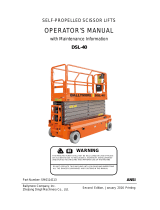
Electrical Schematic
M
11A WH(20)
11A
L
N
PE
+
-
GHAG RD(16)
010B WH(18)
2-1C GN(20)
2-1B YE(20)
9-GND1 BK(18)
GN(18)
RD(18)
BU(18)
YE(18)
WH(18)
JS1
SB4
S2
SB5
SB6
SB7
SB8
PCU
SB3
CAN_L
CAN_H
B3
2
1
4
3
5
2
1
010A RD(16)
SB2
030A-7 RD(20)
SQ4
LRP-2 RD(20)
SQ3
030A-2 RD(18)
010-1 RD(16)
010-2 RD(16)
1B YE(20)
1C GN(20)
030A-9 RD(16)
030A-4 RD(16)
2C RD(16)
4A RD(16)
5A RD(16)
006-3 RD(20)
10B-2 BU(20)
10B-2 WH(20)
B2
2
1
F
L
C
N
H
030A-1 RD(20)
030A-5 RD(20)
010B WH(18)
001C RD(16)
SA1
BK(5)
BK(5)
FU1 130A
001 RD(16)
001B RD(16)
FU2 7A
KA1
SB1
2-GND1 BK(20)
10-GND1 BK(18)
BK(5)
BK(5)
S1
TILT
HL2
S
12C WH(20)
11B WH(20)
12B WH(20)
12A WH(20)
11C WH(20)
3C WH(20)
6B WH(18)
3A WH(20)
3B BK(16)
10B-1 BU(20)
10B WH(20)
9B BU(18)
12C WH (20)
1B
1C
2C
4A
5A
9B
10B
12C
11B
12B
12A
11C
3C
6B
3A
3B
10C
9C
10A
8C
6C
9A
4C
7A
5B
5C
8A
6A
7B
7C
8B
8-GND1 BK(16)
ECU
10C WH(20)
9C WH(20)
10A WH(20)
8C WH(20)
6C WH(20)
9A WH(20)
4C WH(20)
7A WH(20)
5B WH(20)
5C WH(20)
8A-1 WH(20)
8A-2 WH(20)
1
2HM
6A WH(18)
7B WH(18)
7C WH(18)
8B WH(16)
DC- BK(14)
BK(5)
B1
4-GND1 BK(18)
5-GND1 BK(18)
6-GND1 BK(18)
1-GND1 BK(20)
CONTROL+ WH(18)
CONTROL- BU(18)
KM1
BK(5)
B+ B-
8A WH(20)
11
10
15
34
25
14
5
4
3
2
9
8
17
1
12
P
T2
F2
T1
F1
MC1
10B WH(20)
030A-4 RD(16)
EXCITATION WH(16)
BK(5)
BK(8)
BU(11)
BK(8)
BU(11)
RD(8)
BU(11)
RD(8)
BU(11)
M1
M2
M3
BK(5)
L-Brake1 RD(16)
BM1
030A-9 RD(16)
12-GND1 BK(16)
110~220VAC Input
Charger
Joystick
Drive Joystick
Deadman
Steer Left
Steer Right
Lift Enable
Drive Enable
Low Speed
Horn Switch
Platform Ccntrol Module
Lift Indicator
Drive Indicator
Low Speed Indicator
Platform E-STOP
Buzzer
Ground
E-STOP
Left Pothole Switch
Right Pothole Switch
Key Switch
Battery
Relay
Power
Switch
Beacon
Tilt Sensor
Pressure Sensor
Lift Down Valve
Overload Indicator
outdoor Lift Down Limit Switch
Indoor Lift Up Limit Switch
Hourmeter
Lift Up Valve
Steer Left Valve
Steer Right Valve
Horn
DC Contactor
Trac Enable
Forward
Reverse
Trac Speed
MC Speed
Brake
Blink Code Input
MC Enable
Power
Drive Motor(Left)
Drive Motor(Right)
Excitation
Excitation
=16 Position DELPHI Connector LOC2
=16 Position DELPHI Connector LOC3
=2 Position AMP Connector LOC4
=5 Position SIBAS Connector LOC7
Pothole Switch
2B WH(20)
2B
GB2
GB1
SQ2
4
3
5
2
1
k
F
2
4
LED
Brake
Brake
Pump
1
3
2
2
4
PS1
1
3
CANH YE(20)
CANL GN(20)
001A RD(16)
Debugging
8C WH(20)
6C WH(20)
9A WH(20)
4C WH(20)
7A WH(20)
5B WH(20)
5C WH(20)
Lift Up
Lift Down
Buzzer
SV3
SV2
SV1a
SV1b
4
7
2
1
3
586
109
2k?
R2
2k?
R1
LED
001A RD(16)
7-GND1 BK(20)
11-GND1 BK(16)
L-Brake2 BK(16)
R-Brake2 BK(16)
R-Brake1 RD(16)
B
LRP-1 RD(20)
006-2 RD(20)
030A-6 RD(20)
A
006-1 RD(20)
3C WH(20)
11A GN(20)
030A RD(16)
030A-8 RD(18)
A
Beacon RD(18)
HL1
GND6-3 BK(18)
GND6-2 BK(18)
6B WH(18)
GND6-1 BK(18)
1-1B YE(20)
1-1C GN(20)
030A-3 RD(20)
3-GND1 BK(20)
4
3
2
1
BK(5)
Debugging
11B WH (20)
SQ5
030A-7 RD(20)
SA2
SQ1
Selective Switch
C
E
Art_5784
Electrical Schematic
Section 12 - Schematics

Page 41 Mast Series - Service & Parts Manual
May 2021Section 12 - Schematics
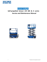
Hydraulic Schematic
P
M
M
SV2
FRV1
SV1
S1
S2
L
T
80bar
IN
SV3
CV1
150bar
SV1a
SV1b
Tank
Pump
Function Valve
Filter
Lower valve
Sensor
Steer Cylinder
Lift Cylinder
Platform overload(Option)
Art_5784

Page 42 Mast Series - Service & Parts Manual
May 2021
Calibration Instructions
The Platform Overload Sensing System may require calibration in the event of a malfunction or
after the replacement of an Overload System component. Proper and correct calibration of the
Overload system is critical for normal and trouble-free machine operation. Read and understand the
instructions before beginning the calibration process.
Calibrate Tilt Sensor
Park the machine on flat level surface.
Note: Calibrating the level sensor requires that the machine be perfectly level on both the X
and Y axis. An inclinometer should be used when ensuring level. Machine power must
be on.
Using the diagram below, locate the “SET ZERO” button located on the side of the sensor. Press
and hold the “SET ZERO” button until the LEDs alternate red and green flashes. Release the
button.
Press the “SET ZERO” button three times. The LEDs will turn off then only the green LED will
illuminate, calibration is complete.
Calibrate Overload System
Note: The platform will lift automatically once the calibration has been initiated. Be sure that there
are no overhead obstructions when choosing a location on which to calibrate the overload
system.
Note: If a safety concern arises anytime during the automated lift/lower sequence, press the
Emergency Stop switch immediately. The procedure can be restarted once it is safe to do so.
Empty Platform Sequence
Park the machine on flat level surface. Machine power must be on. Ensure that the platform is
completely empty and there are no ‘extra’ items attached to the platform or guard rails that may
add weight to the platform beyond that of an empty platform.
Turn the key switch to the Platform position. This will prevent the platform from lifting during the
next step.
Using the lower Lift Switch (located on the lower control panel) perform the following sequence
of up and down movement of the toggle switch. Do not operate the switch so slowly as to hold
the switch more than 2.5 seconds or the sequence will be terminated.
Down 5 times
Up 1 time
Down 5 times
Up 1 time
1.
2.
3.
1.
2.
3.
a.
b.
c.
d.
Section 13 - Calibrations
Calibration Instructions

Page 43 Mast Series - Service & Parts Manual
May 2021Section 13 - Calibrations
Down 1 time
Up 1 time
Down 3 times
The process will be complete when the platform returns to the fully lowered and the horn stops
sounding. Cycle Emergency Stop power and continue to the Loaded calibration steps.
Loaded Platform Sequence
Park the machine on flat level surface. Machine power must be on. Ensure that the platform is
completely empty and there are no ‘extra’ items attached to the platform or guard rails that may
add weight to the platform beyond that of an empty platform.
Place weight in the center of the platform equal to rated platform capacity (500 LBS).
Turn the key switch to the Platform position. This will prevent the platform from lifting during the
next step.
Using the lower Lift Switch (located on the lower control panel) perform the following sequence
of up and down movement of the toggle switch. Do not operate the switch so slowly as to hold
the switch more than 2.5 seconds or the sequence will be terminated.
Down 5 times
Up 1 time
Down 5 times
Up 1 time
Down 5 time
The process will be complete when the platform returns to the fully lowered and the horn stops
sounding. Once the Empty and the Loaded sequences are complete, the Platform Overload
Calibration is complete. Remove weight from platform.
e.
f.
g.
4.
1.
2.
3.
4.
a.
b.
c.
d.
e.
5.

Page 44 Mast Series - Service & Parts Manual
May 2021
Parameter Adjustment
Speed Adjust State
Press and hold HORN and LIFT buttons while pulling the PCU’s
E-Stop (Out) to enter Speed Adjust State.
1.
ART_5785C
“PS” and current Lift Speed are alternately flashing on the display.
Release LIFT and HORN buttons.
2.
ART_5785D
Drive High Speed with Platform Stowed
Press DRIVE button. The DRIVE LED indicates this mode is
active. Adjust the speed using the RIGHT TURN (Increase) or
LEFT TURN (Decrease) button on the top of the Joystick.
1.
ART_5785E
The value can be changed from 00 to 100 (displays 9˙9) with the
buttons on top of the Joystick.
2.
ART_5785F
Drive Low Speed
Press DRIVE button. Press and hold the LOW SPEED button to
select Drive Low Speed adjustment. Keep it held while adjusting
the speed. The display indicates present set value. Adjust using
the RIGHT TURN (Increase) or LEFT TURN (Decrease) button on
top of the Joystick.
1.
ART_5785G
The value can be changed from 00 to 100 (displays 9˙9) with the
buttons on top of the Joystick.
2.
ART_5785F
Section 14 - Parameter Adjustments
Parameter Adjustment

Page 45 Mast Series - Service & Parts Manual
May 2021Section 14 - Parameter Adjustments
Drive Elevated Speed
Elevated Drive Speed is an important safety parameter set at the factory.
Changing this parameter should only be conducted with express
instructions from MEC Product Support Department.
Press DRIVE button. Press and hold the HORN button to select
Drive Elevated Speed adjustment. Keep it held while adjusting
the speed. The display will indicate the present set value. Adjust
the speed using the RIGHT TURN (Increase) or LEFT TURN
(decrease) button on top of the Joystick.
1.
ART_5785H
The value can be changed from 00 to Max Speed (see table
below) with the buttons on top of the Joystick.
Position Drive Speed
Stowed 3.7 ft/sec (1.11 m/sec)
Raised 1.03 ft/sec (0.31 m/sec)
2.
ART_5785I
Lift Speed
Press LIFT button. The LIFT LED indicates this mode is active.
Adjust the speed using the RIGHT TURN (Increase) or LEFT
TURN (Decrease) button on top of the Joystick.
1.
ART_5785J
The value can be changed from 00 to 100 (displays 9˙9) with the
buttons on top of the Joystick.
2.
ART_5785F
Steering Speed
Press DRIVE button. Press and hold the HORN and LOW SPEED
buttons to select. Drive Steering Speed adjustment. Hold these
buttons while adjusting the speed. Display indicates the present
set value. Adjust the speed using the RIGHT TURN (Increase) or
LEFT TURN (Decrease) button on top of the Joystick.
1.
ART_5785K
The value can be changed from 00 to 100 (displays 9˙9) with the
buttons on top of the Joystick.
2.
ART_5785F

Page 46 Mast Series - Service & Parts Manual
May 2021Section 14 - Parameter Adjustments
Machine Options State - Selecting Machine Options
Press and hold the LIFT and HORN buttons while pulling the
PCU’s E-Stop out to select Machine Options adjustment.
1.
ART_5785Q
“PS” and Elevated Speed value will alternatively flash on the
display.
2.
ART_5785D
Release LIFT and HORN buttons.3.
ART_5785L
“PS” will change to Lift Speed.4.
ART_5785F
Getting To The Machine Option Selection Mode
Press and hold the LIFT and LOW SPEED buttons for 3 seconds
to enter the Machine Option selection mode.
1.
ART_5785M
“SC” is displayed when in Machine Option selection mode.2.
ART_5785N
Entering The Machine Option Selection Mode
Momentarily press DRIVE button to edit the right digit. The digit will
be flashing.
1.
ART_5785E

Page 47 Mast Series - Service & Parts Manual
May 2021Section 14 - Parameter Adjustments
Then press LIFT button to edit the left digit. The Left digit will now
be flashing.
2.
ART_5785J
The buttons on the top of the Joystick increase (LEFT TURN
button) or decrease (RIGHT TURN button) the flashing digit.
3.
ART_5785O
Press the HORN button, the dot will disappear.4.
ART_5785H
Save The New Values
Press the HORN button for 3 seconds to save changes.
Turn OFF power and ON to operate the machine with the new
values.
1.
2.
ART_5785P
-
 1
1
-
 2
2
-
 3
3
-
 4
4
-
 5
5
-
 6
6
-
 7
7
-
 8
8
-
 9
9
-
 10
10
-
 11
11
-
 12
12


Mec MME25 Schematic Diagram
- Type
- Schematic Diagram
- This manual is also suitable for
Ask a question and I''ll find the answer in the document
Finding information in a document is now easier with AI
Related papers
-
Mec Micro19® - A92.20 Operating instructions
-
-
-
-
-
-
-
-
-
Other documents
-
 DINGLI S0812EH Operators Manual With Maintenance Information
-
 Ballymore DSL-40 User manual
-
Terex Genie QS-20R User manual
-
Genie Z-80/60 Service and Repair Manual
-
Genie S-40 TRAX User manual
-
Terex Genie GS-3369 BE User manual
-
-
-
JCB S2032E Quick start guide
-
 Upright MX SERIES Service And Maintenance Manual


