Gigabyte GA-K8N51PVMT-9-RH User manual

Category
Server/workstation motherboards
Type
User manual
GA-K8N51PVMT-9-RH
AMD Socket 939 Processor Motherboard
User's Manual
Rev. 1001
12ME-51PVMT9R-1001R
* The WEEE marking on the product indicates this product must not be disposed of with user's other household waste
and must be handed over to a designated collection point for the recycling of waste electrical and electronic equipment!!
* The WEEE marking applies only in European Union's member states.
Motherboard
GA-K8N51PVMT-9-RH
Mar. 1, 2006
Mar. 1, 2006
Motherboard
GA-K8N51PVMT-9-RH
Copyright
© 2006 GIGA-BYTE TECHNOLOGY CO., LTD. All rights reserved.
The trademarks mentioned in the manual are legally registered to their respective companies.
Notice
The written content provided with this product is the property of Gigabyte.
No part of this manual may be reproduced, copied, translated, or transmitted in any form or by any
means without Gigabyte's prior written permission. Specifications and features are subject to
change without prior notice.
Product Manual Classification
In order to assist in the use of this product, Gigabyte has categorized the user manual in the
following:
î‚„ For detailed product information and specifications, please carefully read the
"Product User Manual".
î‚„ For detailed information related to Gigabyte's unique features, please go to the
"Technology Guide" section on Gigabyte's website to read or download the information
you need.
For more product details, please click onto Gigabyte's website at www.gigabyte.com.tw
- 4 -
Table of Contents
GA-K8N51PVMT-9-RH Motherboard Layout ................................................................. 6
Block Diagram ................................................................................................................ 7
Chapter 1 Hardware Installation .................................................................................... 9
1-1 Considerations Prior to Installation .................................................................... 9
1-2 Feature Summary .......................................................................................... 10
1-3 Installation of the CPU and CPU Cooler ....................................................... 12
1-3-1 Installation of the CPU ......................................................................................... 12
1-3-2 Installation of the CPU Cooler ............................................................................ 13
1-4 Installation of Memory .................................................................................... 14
1-5 Installation of Expansion Cards ...................................................................... 16
1-6 I/O Back Panel Introduction ........................................................................... 17
1-7 Connectors Introduction .................................................................................. 19
Chapter 2 BIOS Setup................................................................................................ 29
The Main Menu (For example: BIOS Ver. : F3a)...................................................... 30
2-1 Standard CMOS Features ............................................................................. 32
2-2 Advanced BIOS Features .............................................................................. 34
2-3 Integrated Peripherals ..................................................................................... 36
2-4 Power Management Setup ............................................................................. 39
2-5 PnP/PCI Configurations ................................................................................. 41
2-6 PC Health Status ........................................................................................... 42
2-7 Frequency/Voltage Control ............................................................................. 44
2-8 Load Fail-Safe Defaults ................................................................................... 45
2-9 Load Optimized Defaults ................................................................................. 45
2-10 Set Supervisor/User Password ..................................................................... 46
2-11 Save & Exit Setup ......................................................................................... 47
2-12 Exit Without Saving ....................................................................................... 47
- 5 -
Chapter 3 Drivers Installation ...................................................................................... 49
3-1 Install Chipset Drivers .................................................................................... 49
3-2 Software Application ....................................................................................... 50
3-3 Software Information ....................................................................................... 50
3-4 Hardware Information ..................................................................................... 51
3-5 Contact Us ..................................................................................................... 51
3-6 Connecting the Video Output Devices ............................................................ 52
Chapter 4 Appendix ................................................................................................... 53
4-1 Unique Software Utilities ................................................................................ 53
4-1-1 EasyTune 5 Introduction ..................................................................................... 53
4-1-2 Xpress Recovery2 Introduction ......................................................................... 54
4-1-3 Flash BIOS Method Introduction ........................................................................ 56
4-1-4 Configuring SATA Hard Drive(s) ........................................................................ 65
4-1-5 2- / 4- / 6- / 8- Channel Audio Function Introduction ...................................... 79
4-2 Troubleshooting ............................................................................................... 84
- 6 -
GA-K8N51PVMT-9-RH Motherboard Layout
KB_MS
ATX_12V
CPU_FAN
AUDIO2
nVIDIA
®
GeForce 6150
SPDIF_IO
CODEC
VGA
LPT
USB
LAN
VIA
VT6307
F_PANEL1
BIOS
PCI1
PCI2
VITESSE
8201
F_AUDIO
F_USB2F_USB1
BAT
ATX
IDE2
FDD
CLR_CMOS
SYS_FAN
CD_IN
GA-K8N51PVMT-9-RH
COMA
PCIE_16
CI
Socket 939
IDE1
DDR1
DDR2
DDR3
DDR4
PCIE_1
F1_1394
W83627
nVIDIA
®
nForce 430
AUDIO1
USB
1394
TV
SATAII0_1 SATAII2_3
PWR_LED
- 7 -
Block Diagram
AMD K8
Socket 939
CPU
CPUCLK+/-(200MHz)
Hyper Transport
Bus
PCICLK
(33MHz)
2 PCI
PCI Bus
1 PCI Express x 1
PCI Express Bus
nVIDIA
®
GeForce 6150
nVIDIA
®
nForce 430
2 IEEE1394
VT6307
DDR 400/333/266/
200MHz DIMM
Dual Channel Memory
4 SATA 3Gb/s
8 USB
Ports
Line-Out
MIC
CODEC
Line-In
SPDIF In
SPDIF Out
Side Speaker Out
Center/Subwoofer Speaker Out
Surround Speaker Out
ATA33/66/100/133
IDE Channels
x1
PCI-ECLK
(100MHz)
PCI-ECLK
(100MHz)
PCI Express x 16
LAN
RJ45
VITESSE
8201
LPC BUS
48 MHz
33 MHz
Floppy
LPT Port
PS/2 KB/Mouse
COMA
Winbond
W83627
VGA
BIOS
TV Out
- 8 -
Hardware Installation- 9 -
English
1-1 Considerations Prior to Installation
Preparing Your Computer
The motherboard contains numerous delicate electronic circuits and components which can
become damaged as a result of electrostatic discharge (ESD). Thus, prior to installation, please
follow the instructions below:
1. Please turn off the computer and unplug its power cord.
2. When handling the motherboard, avoid touching any metal leads or connectors.
3. It is best to wear an electrostatic discharge (ESD) cuff when handling electronic components
(CPU, RAM).
4. Prior to installing the electronic components, please have these items on top of an antistatic
pad or within a electrostatic shielding container.
5. Please verify that the power supply is switched off before unplugging the power supply connector
from the motherboard.
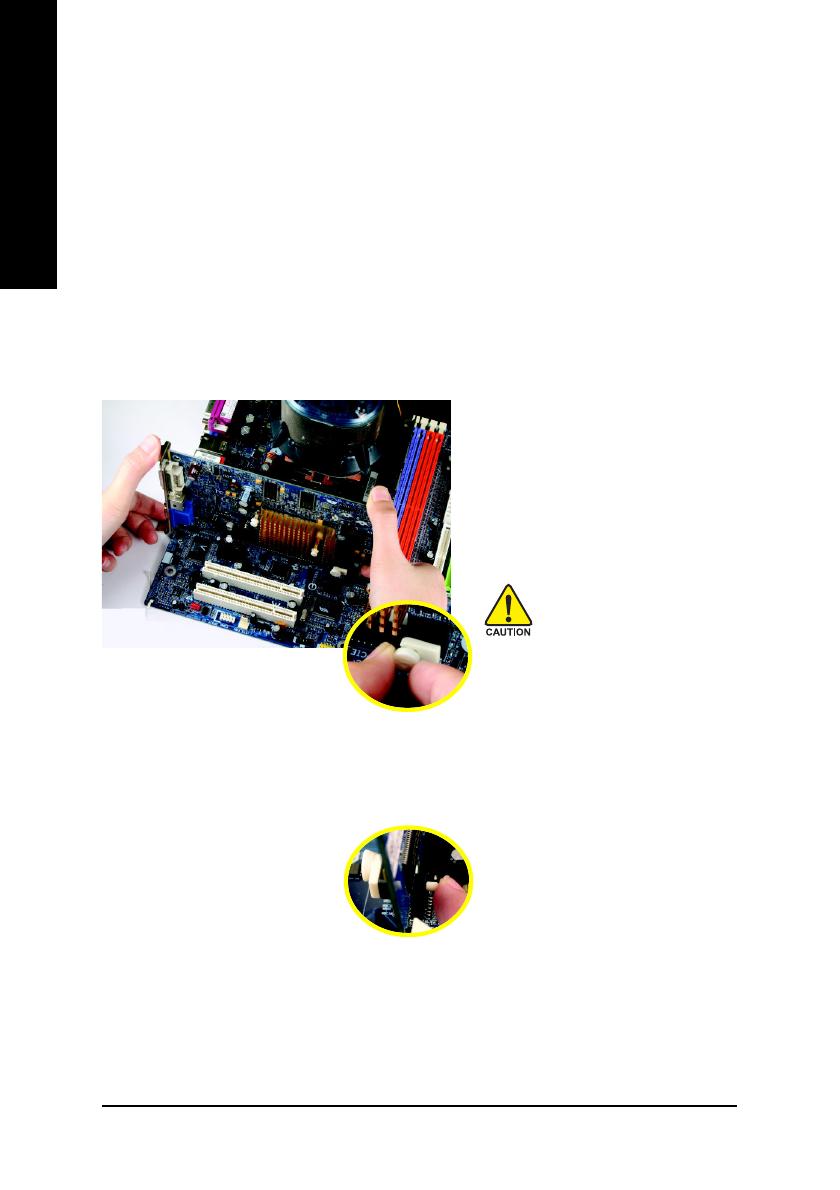
Installation Notices
1. Prior to installation, please do not remove the stickers on the motherboard. These stickers
are required for warranty validation.
2. Prior to the installation of the motherboard or any hardware, please first carefully read the
information in the provided manual.
3. Before using the product, please verify that all cables and power connectors are connected.
4. To prevent damage to the motherboard, please do not allow screws to come in contact with
the motherboard circuit or its components.
5. Please make sure there are no leftover screws or metal components placed on the motherboard
or within the computer casing.
6. Please do not place the computer system on an uneven surface.
7. Turning on the computer power during the installation process can lead to damage to system
components as well as physical harm to the user.
8. If you are uncertain about any installation steps or have a problem related to the use of the
product, please consult a certified computer technician.
Instances of Non-Warranty
1. Damage due to natural disaster, accident or human cause.
2. Damage as a result of violating the conditions recommended in the user manual.
3. Damage due to improper installation.
4. Damage due to use of uncertified components.
5. Damage due to use exceeding the permitted parameters.
6. Product determined to be an unofficial Gigabyte product.
Chapter 1Hardware Installation
GA-K8N51PVMT-9-RH Motherboard - 10 -
English
1-2 Feature Summary
CPU î‚Š Socket 939 for AMD Sempron
TM
/ Althlon
TM
64 / Althlon
TM
64 FX /
Althlon
TM
64 X2 Dual-Core processor (K8)
î‚Š Supports core frequencies in excess of 3000+ and faster
System Bus î‚Š 2000MHz
Chipset î‚Š Northbridge: nVIDIA
®
GeForce 6150
Southbridge: nVIDIA
®
nForce 430
LAN î‚Š Onboard VITESSE 8201 phy (10/100/1000Mbit)
Audio î‚Š Onboard Realtek ALC880 chip
î‚Š High Definition Audio
î‚Š Supports 2 / 4 / 6/ 8 channel audio
î‚Š Supports SPDIF In/Out connection
î‚Š Supports CD In connection
Storage î‚Š nVIDIA
®
nForce 430 chipset
- 1 FDD connector, allowing connection of 1 FDD device
- 2 IDE connectors (IDE1, IDE2) with UDMA 33/ATA 66/ATA 100/ATA 133
suppport, allowing connection of 4 IDE devices
- 4 SATA 3Gb/s connectors (SATAII0_1, SATAII2_3), allowing connection
of 4 SATA 3Gb/s devices
- Supports data striping (RAID 0), mirroring (RAID 1),
striping + mirroring (RAID 0+1), RAID 5 for Serial ATA
O.S Support î‚Š Microsoft Windows 2000/XP
Memory î‚Š 4 DDR DIMM memory slots (supports up to 4 GB memory)
(Note 1)
î‚Š Supports dual channel DDR 400/333/266/200 DIMMs
î‚Š Supports 2.5V DDR DIMMs
Expanstion Slots î‚Š 1 PCI Express x16 slot
î‚Š 1 PCI Express x1 slot
î‚Š 2 PCI slots
Internal Connectors î‚Š 1 24-pin ATX power connector
î‚Š 1 4-pin ATX 12V power connector
î‚Š 1 floppy connector
î‚Š 2 IDE connectors
î‚Š 4 SATA 3Gb/s connectors
î‚Š 1 CPU fan connector
î‚Š 1 system fan connector
î‚Š 1 front panel connector
î‚Š 1 front audio connector
î‚Š 1 CD In connector
î‚Š 2 USB 2.0/1.1 connectors for additional 4 USB 2.0/1.1 ports by cables
î‚Š 1 IEEE1394 connector for 1 additional IEEE1394 port by cable
î‚Š 1 SPDIF in/out connector
î‚Š 1 COMA connector
î‚Š 1 power LED connector
Hardware Installation- 11 -
English
Rear Panel I/O î‚Š 1 PS/2 keyboard port
î‚Š 1 PS/2 mouse port
î‚Š 1 parallel port
î‚Š 1 TV out port
î‚Š 1 VGA port
(Note 2)
î‚Š 1 IEEE1394 port
î‚Š 4 USB 2.0/1.1 ports
î‚Š 1 RJ-45 port
î‚Š 6 audio jacks (Line In / Line Out / MIC In / Surround Speaker Out(Rear
Speaker Out) / Center/Subwoofer Speaker Out / Side Speaker Out)
I/O Control î‚Š W83627 chip
Hardware Monitor î‚Š System voltage detection
î‚Š CPU / system temperature detection
î‚Š CPU / system fan speed detection
î‚Š CPU warning temperature
î‚Š CPU /system fan failure warning
î‚Š CPU smart fan control
(Note 3)
BIOS î‚Š 1 4Mbit flash ROM
î‚Š Use of licensed AWARD BIOS
Additional Features î‚Š Supports @BIOS
î‚Š Supports Download Center
î‚Š Supports Q-Flash
î‚Š Supports EasyTune
(Note 4)
î‚Š Supports Xpress Install
î‚Š Supports Xpress Recovery2
î‚Š Supports Xpress Rescue
Bundle Software î‚Š Norton Internet Security (OEM version)
Form Factor î‚Š Micro ATX form factor; 24.4cm x 24.4cm
(Note 1) Due to standard PC architecture, a certain amount of memory is reserved for system usage
and therefore the actual memory size is less than the stated amount.
For example, 4 GB of memory size will instead be shown as 3.xxGB memory during system
startup.
(Note 2) You can only use either the TV out port or the VGA port as the vedio output port, not both
together.
(Note 3) Whether the CPU Smart FAN Control function is supported will depend on the CPU you install.
For more detailed information please check at the FAQ section on GIGABYTE's website.
(Note 4) EasyTune functions may vary depending on different motherboards.
GA-K8N51PVMT-9-RH Motherboard - 12 -
English
1-3 Installation of the CPU and CPU Cooler
1-3-1 Installation of the CPU
Check the CPU pins to see that none are bent. Move the socket lever to the unlocked position as shown
in Fig. 1 (90
o
to the plane of the motherboard) prior to inserting the CPU. The pin 1 location is designated
on the CPU by a small triangle that corresponds to a triangle marking on the socket as shown in Fig.
2. Align the CPU to the socket and gently lower it into place. Do not force the CPU into the socket.
Fig.1
Position lever at a 90 degree angle.
Socket lever
Fig.2
Pin 1 location on the socket and processor.
Gently place the CPU into position making sure that the CPU pins fit
perfectly into their holes. Once the CPU is positioned into its socket,
place one finger down on the middle of the CPU and gently press the
metal lever back into its original position.
Please use extra care when installing the CPU. The CPU will not fit if positioned incorrectly.
Rather than applying force, please change the positioning of the CPU.
Before installing the CPU, please comply with the following conditions:
1. Please make sure that the motherboard supports the CPU.
2. Please take note of the pin 1 marking (the small triangle) on the CPU. If you install the
CPU in the wrong direction, the CPU will not insert properly. If this occurs, please
change the insert direction of the CPU.
3. Please add an even layer of heat paste between the CPU and CPU cooler.
4. Please make sure the CPU cooler is installed on the CPU prior to system use,
otherwise overheating and permanent damage of the CPU may occur.
5. Please set the CPU host frequency in accordance with the processor specifications.
It is not recommended that the system bus frequency be set beyond hardware specifica-
tions since it does not meet the required standards for the peripherals. If you wish to set
the frequency beyond the proper specifications, please do so according to your hard-
ware specifications including the CPU, graphics card, memory, hard drive, etc.
Hardware Installation- 13 -
English
1-3-2 Installation of the CPU Cooler
The CPU cooler may adhere to the CPU as a result of hardening of the heat paste. To prevent
such an occurrence, it is suggested that either thermal tape rather than heat paste be used for
heat dissipation or using extreme care when removing the CPU cooler.
Fig.1
Before installing the CPU cooler, please first add an even layer of heat
paste on the surface of the CPU. Install all the CPU cooler components
(Please refer to the cooler manual for detailed installation instructions).
Fig.2
Please connect the CPU cooler power connector to the CPU_FAN con-
nector located on the motherboard so that the CPU cooler can properly
function to prevent CPU overheating.
GA-K8N51PVMT-9-RH Motherboard - 14 -
English
Before installing the memory modules, please comply with the following conditions:
1. Please make sure that the memory used is supported by the motherboard. It is
recommended that memory of similar capacity, specifications and brand be used.
2. Before installing or removing memory modules, please make sure that the computer power
is switched off to prevent hardware damage.
3. Memory modules have a foolproof insertion design. A memory module can be installed in
only one direction. If you are unable to insert the module, please switch the direction.
1-4 Installation of Memory
The motherboard supports DDR memory modules, whereby BIOS will automatically detect memory
capacity and specifications. Memory modules are designed so that they can be inserted only in one direction.
The memory capacity used can differ with each slot.
Notch
DDR
Fig.1
The DIMM socket has a notch, so the DIMM memory module can only
fit in one direction. Insert the DIMM memory module vertically into the
DIMM socket. Then push it down.
Fig.2
Close the plastic clip at both edges of the DIMM sockets to lock the
DIMM module.
Reverse the installation steps when you wish to remove the DIMM
module.
Hardware Installation- 15 -
English
Dual Channel Memory Configuration
The GA-K8N51PVMT-9-RH supports the Dual Channel Technology. When the Dual Channel Technol-
ogy is activated, the bandwidth of memory bus will be double the original one.
Due to CPU limitation, if you want to operate the Dual Channel Technology, please follow the guidelines
below for Dual Channel memory configuration.
1. Dual Channel mode will not be enabled if only one DDR memory module is installed.
2. To enable Dual Channel mode with 2 memory modules (it is recommended to use memory
modules of identical brand, size, chips, and speed), you must install them into DIMM sockets
of the same color.
3. To enable Dual Channel mode with 4 memory modules, it is recommended to use memory
modules of identical brand, size, chips, and speed.
The following is a Dual Channel Memory configuration table: (DS: Double Side, SS: Single Side)
2 memory modules
4 memory modules
DDR 1 DDR 2 DDR 3 DDR 4
DS/SS DS/SS X X
X X DS/SS DS/SS
DS/SS DS/SS DS/SS DS/SS
1 memory module
2 memory modules
3 memory modules
DDR 1 DDR 2 DDR 3 DDR 4
X DS/SS X X
X X X DS/SS
X DS/SS DS/SS X
DS/SS X X DS/SS
X DS/SS X DS/SS
DS/SS DS/SS DS/SS X
X DS/SS DS/SS DS/SS
DS/SS X DS/SS DS/SS
DS/SS DS/SS X DS/SS
All of the memory configurations below will cause system unable to boot.
(DS: Double Side, SS: Single Side)
If two memory modules are to be used to achieve Dual Channel mode, we recommend
installing them in DDR1 and DDR2 DIMM sockets.
GA-K8N51PVMT-9-RH Motherboard - 16 -
English
1-5 Installation of Expansion Cards
You can install your expansion card by following the steps outlined below:
1. Read the related expansion card's instruction document before install the expansion card into the
computer.
2. Remove your computer's chassis cover, screws and slot bracket from the computer.
3. Press the expansion card firmly into expansion slot in motherboard.
4. Be sure the metal contacts on the card are indeed seated in the slot.
5. Replace the screw to secure the slot bracket of the expansion card.
6. Replace your computer's chassis cover.
7. Power on the computer, if necessary, setup BIOS utility of expansion card from BIOS.
8. Install related driver from the operating system.
Installing a PCI Express x 16 expansion card:
To release an installed card, users can
also press the latch on the opposite side
of the drawable bar as the picture to the
left shows.
Please carefully pull out the small white-
drawable bar at the end of the PCI Ex-
press x 16 slot when you try to install/
uninstall the VGA card. Please align the
VGA card to the onboard PCI Express x
16 slot and press firmly down on the slot.
Make sure your VGA card is locked by
the small white-drawable bar.
Hardware Installation- 17 -
English
1-6 I/O Back Panel Introduction
PS/2 Keyboard and PS/2 Mouse Connector
To install a PS/2 port keyboard and mouse, plug the mouse to the upper port (green) and the
keyboard to the lower port (purple).
Parallel Port
The parallel port allows connection of a printer, scanner and other peripheral devices.
TV Out Port
(Note 1)
HDTV, NTSC / PAL TV and Projector etc. can be connected to TV Out.
VGA Port
(Note 2)
Monitor can be connected to VGA port.
IEEE 1394 Port
Serial interface standard set by Institute of Electrical and Electronics Engineers, which has features
like high speed, high bandwidth and hot plug.
USB port
Before you connect your device(s) into USB connector(s), please make sure your device(s) such
as USB keyboard, mouse, scanner, zip, speaker...etc. have a standard USB interface.
Also make sure your OS supports USB controller. If your OS does not support USB controller,
please contact OS vendor for possible patch or driver upgrade. For more information please
contact your OS or device(s) vendors.
LAN Port
The provided Internet connection is Gigabit Ethernet , providing data transfer speeds of 10/100/
1000Mbps.
Line In
(Note 3)
The default Line In jack. Devices like CD-ROM, walkman etc. can be connected to Line In jack.
Line Out (Front Speaker Out)
The default Line Out (Front Speaker Out) jack. Stereo speakers, earphone or front surround
speakers can be connected to Line Out (Front Speaker Out) jack.
MIC In
The default MIC In jack. Microphone must be connected to MIC In jack.
Center/Subwoofer Speaker Out
The default Center/Subwoofer Speaker Out jack. Center/Subwoofer speakers can be connected to
Center/Subwoofer Speaker Out jack.
Surround Speaker Out (Rear Speaker Out)
The default Surround Speaker Out (Rear Speaker Out) jack. Rear surround speakers can be
connected to Surround Speaker Out (Rear Speaker Out) jack.
Side Speaker Out
The default Side Speaker Out jack. Surround side speakers can be connected to Side Speaker Out
jack.
GA-K8N51PVMT-9-RH Motherboard - 18 -
English
(Note 2) You can only use either the TV out port or the VGA port as the vedio output port, not both
together.
(Note 3) You can use audio software to configure 2-/4-/6-/8-channel audio functioning.
Y
SVID OUT
(S-Video Output)
(HDTV Component)
Pr Pb/AV
TV Out
(Note 1) Video Adapter Introduction
(1) Connecting HDTV
Connect your HDTV cables to the video adapter according to the
corresponding color. (Y= Green, Pr= Red, Pb= Blue)
(2) Connecting S-Video
If your TV has a S-Video connection, connect the S-Video cable
from your TV to the S-Video Out port (SVID OUT) on the adapter.
(3) Connecting AV Output
If your TV has a Composite video connection, you can connect
the RCA cable from your TV to the AV Out port (Pb/AV) on the
adapter.
HDTV
NTSC/PAL TV
Projector
Pb/AV
Pr
Y
S-Video Output
Video Adapter
TV Out Port
Hardware Installation- 19 -
English
1-7 Connectors Introduction
1) ATX_12V
2) ATX (Power Connector)
3) CPU_FAN
4) SYS_FAN
5) FDD
6) IDE1 / IDE2
7) SATAII0_1 / SATAII2_3
8) PWR_LED
9) BATTERY
10) F_PANEL
11) F_AUDIO
12) CD_IN
13) F_USB1 / F_USB2
14) F1_1394
15) SPDIF_IO
16) COMA
17) CLR_CMOS
18) CI
13
17
6
8
2
11
12
9
13
7
4
10
14
5
15 16
18
GA-K8N51PVMT-9-RH Motherboard - 20 -
English
1/2) ATX_12V / ATX (Power Connector)
With the use of the power connector, the power supply can supply enough stable power to all the
components on the motherboard. Before connecting the power connector, please make sure that
all components and devices are properly installed. Align the power connector with its proper
location on the motherboard and connect tightly.
The ATX_12V power connector mainly supplies power to the CPU. If the ATX_12V power
connector is not connected, the system will not start.
Caution!
Please use a power supply that is able to handle the system voltage requirements. It is
recommended that a power supply that can withstand high power consumption be used (300W or
greater). If a power supply is used that does not provide the required power, the result can lead
to an unstable system or a system that is unable to start.
If you use a 24-pin ATX power supply, please remove the small cover on the power connector
on the motherboard before plugging in the power cord; otherwise, please do not remove it.
Pin No. Definition
1 GND
2 GND
3 +12V
4 +12V
Pin No. Definition
13 3.3V
14 -12V
15 GND
16 PS_ON(soft On/Off)
17 GND
18 GND
19 GND
20 -5V
21 +5V
22 +5V
23 +5V (Only for 24-pin ATX)
24 GND(Only for 24-pin ATX)
Pin No. Definition
1 3.3V
2 3.3V
3 GND
4 +5V
5 GND
6 +5V
7 GND
8 Power Good
9 5V SB(stand by +5V)
10 +12V
11 +12V(Only for 24-pin ATX)
12 3.3V(Only for 24-pin ATX)
13
1
24
12
3
1
4
2
  • Page 1 1
  • Page 2 2
  • Page 3 3
  • Page 4 4
  • Page 5 5
  • Page 6 6
  • Page 7 7
  • Page 8 8
  • Page 9 9
  • Page 10 10
  • Page 11 11
  • Page 12 12
  • Page 13 13
  • Page 14 14
  • Page 15 15
  • Page 16 16
  • Page 17 17
  • Page 18 18
  • Page 19 19
  • Page 20 20
  • Page 21 21
  • Page 22 22
  • Page 23 23
  • Page 24 24
  • Page 25 25
  • Page 26 26
  • Page 27 27
  • Page 28 28
  • Page 29 29
  • Page 30 30
  • Page 31 31
  • Page 32 32
  • Page 33 33
  • Page 34 34
  • Page 35 35
  • Page 36 36
  • Page 37 37
  • Page 38 38
  • Page 39 39
  • Page 40 40
  • Page 41 41
  • Page 42 42
  • Page 43 43
  • Page 44 44
  • Page 45 45
  • Page 46 46
  • Page 47 47
  • Page 48 48
  • Page 49 49
  • Page 50 50
  • Page 51 51
  • Page 52 52
  • Page 53 53
  • Page 54 54
  • Page 55 55
  • Page 56 56
  • Page 57 57
  • Page 58 58
  • Page 59 59
  • Page 60 60
  • Page 61 61
  • Page 62 62
  • Page 63 63
  • Page 64 64
  • Page 65 65
  • Page 66 66
  • Page 67 67
  • Page 68 68
  • Page 69 69
  • Page 70 70
  • Page 71 71
  • Page 72 72
  • Page 73 73
  • Page 74 74
  • Page 75 75
  • Page 76 76
  • Page 77 77
  • Page 78 78
  • Page 79 79
  • Page 80 80
  • Page 81 81
  • Page 82 82
  • Page 83 83
  • Page 84 84
  • Page 85 85
  • Page 86 86
  • Page 87 87
  • Page 88 88

Gigabyte GA-K8N51PVMT-9-RH User manual

Category
Server/workstation motherboards
Type
User manual

Ask a question and I''ll find the answer in the document

Finding information in a document is now easier with AI