Page is loading ...

Instructions for Use
Owner’s Reference
THE LEADER IN AUDIO ENGINEERING
KAV–280p
Remote Control
Preamplifier

Krell Industries, Inc.
45 Connair Road
Orange, CT 06477-3650 USA
TEL 203-799-9954
FAX 203-891-2028
E-MAIL [email protected]
WEBSITE http://www.krellonline.com
This product complies with the EMC directive (89/336/EEC) and the low-voltage
directive (73/23/EEC).
Do not place the preamplifier where it could be exposed to dripping or splashing.
The ventilation grids on the top and bottom of the KAV–280p must be unob-
structed at all times during operation. Do not place flammable material on top of
or beneath the component.
Do not remove or bypass the ground pin on the end of the AC cord. This may
cause RFI (radio frequency interference) to be induced into your playback sys-
tem.
When making connections to this or any other component, make sure all compo-
nents are off. Turn off all systems’ power before connecting the KAV–280p to any
other component. Make sure all cable terminations are of the highest quality, free
from frayed ends, short circuits, or cold solder joints.
When the line fuse needs to be replaced, use the spare fuse provided. Unplug
the component before replacing the fuse.
THERE ARE NO USER-SERVICEABLE PARTS INSIDE ANY KRELL PRODUCT.
Please contact your authorized dealer, distributor, or Krell if you have any ques-
tions not addressed in this reference manual.
This product is manufactured in the United States of America. Krell
®
is a registered trademark of Krell
Industries, Inc., and is restricted for use by Krell Industries, Inc., its subsidiaries, and authorized agents.
Krell Current Mode™ and Theater Throughput™ are trademarks of Krell Industries, Inc. All other trade-
marks and trade names are registered to their respective companies.
© 2002 by Krell Industries, Inc. All rights reserved P/N 306429
KAV–280p
Remote Control Preamplifier
Instructions for Use
v 02.0
CONTACT
INFORMATION
WARNINGS

Krell KAV–280p iii
Contents
Page
INTRODUCTION 1
DEFINITION OF TERMS 2
UNPACKING 3
PLACEMENT 4
AC Power Guidelines 4
FRONT PANEL DESCRIPTION 6
BACK PANEL DESCRIPTION 9
REMOTE CONTROL DESCRIPTION 12
Battery Installation and Removal 12
Remote Control Functions 12
CONNECTING THE KAV–280p TO YOUR SYSTEM 15
Connection Steps 15
OPERATING YOUR KAV–280p 16
Preamplifier Operation 16
Tape Input and Output 17
CONFIGURING THE KAV–280p
FOR THEATER THROUGHPUT 19
HOW TO TROUBLESHOOT SYSTEM NOISE 20
QUESTIONS AND ANSWERS 21
WARRANTY 22
RETURN AUTHORIZATION PROCEDURE 23
SPECIFICATIONS Back Cover

iv Krell KAV–280p
Illustrations
FIGURE 1 The KAV–280p Front Panel 5
FIGURE 2 The KAV–280p Back Panel 8
FIGURE 3 The KAV–280p Remote Control 11
Page

Krell KAV–280p 1
Introduction
Thank you for your purchase of the Krell KAV–280p Remote
Control Preamplifier. The KAV-280p uses current mode and sur-
face mount technologies derived directly from the state-of-the-art
Krell KCT Preamplifier.
The Class A direct-coupled design of the KAV–280p means that
the signal path is fully balanced from input to output. This includes
a fully balanced volume control. Circuits are powered by a dedicat-
ed supply with discrete voltage regulators and there is a separate,
dedicated power supply for all digital control circuits. All signal
switching is accomplished via hermetically sealed multiple contact
precision relays.
The KAV–280p provides a high level of operational convenience
and functional versatility. It is easy to integrate into your system.
The remote control accesses all amplifier functions, and remote
control connection options on the back panel allow the KAV–280p
to be easily connected with other components. With its unique
Theater Throughput
TM
feature, the KAV–280p can easily adapt to
home theater applications.
This owner’s reference manual contains important information on
the placement, installation, and operation of the KAV–280p.
Please read this information carefully. A thorough understanding of
these details will help ensure satisfactory operation and long life
for your KAV–280p and related system components.

Definition of Terms
OPERATION
Following are the definitions of key terms used in your owner’s ref-
erence manual.
Theater Throughput
Theater Throughput is a Krell configuration option that allows the
signal from a surround preamp/processor to pass through a Krell
preamplifier or integrated amplifier with no gain, for integrated vol-
ume and balance management of Krell home theater systems.
Balanced
A symmetrical input or output circuit that has equal impedance
from both input terminals to a common ground reference point.
The industry standard for professional and sound recording instal-
lations, balanced connections have 6 dB more gain than single-
ended connections and allow the use of long interconnect cables.
Balanced connections are completely immune to induced noise
from the system or the environment.
Single-ended
A two-wire input or output circuit. Use care when using single-
ended connections as the ground connection is made last and
broken first. Turn the system off prior to making or breaking single-
ended connections. Single-ended connections are not recom-
mended for connections requiring long cable runs.
Off
The component is off when the AC power cord is unplugged from
the wall receptacle.
Stand-by Mode
Alow power consumption status that keeps the audio circuits at
idle. When you plug the AC power cord into the wall receptacle,
the red stand-by LED illuminates. The component is now ready to
be switched to the operational mode. Krell recommends leaving
the component in the stand-by mode when it is not playing music.
Operational Mode
When the component is in the stand-by mode, and you press the
power button on the front panel or the power key on the remote
control, the blue power LED illuminates. The component is in the
operational mode and is ready to play music.
CONFIGURATIONS
INPUT AND OUTPUT
CONNECTIONS
2 Krell KAV–280p

Definition of Terms, continued
Krell Current Mode
A proprietary Krell circuit topology in which the audio gain stages
of a component operate in the current rather than voltage domain.
This unique technology provides the component with exceptional
speed and a wide bandwidth.
Surface Mount Technology (SMT)
SMT allows individual circuit elements to be placed very close
together. This shortens signal paths and allows circuit elements to
operate at the same temperature, resulting in more accurate signal
transfer and enhanced reliability.
TECHNOLOGY
Krell KAV–280p 3
Unpacking
1. Open the shipping box and remove the top layer of foam. The
following items are visible:
1KAV–280p Remote Control Preamplifier
1Accessory Kit containing:
1 AC power cord
1 12 VDC (12 V trigger) cable
1 KAV–280p remote control
1 CR2025 lithium battery for the remote
1 Packet containing the owner’s reference and the warranty
registration card.
2. Grasp the underside of the preamplifier and lift it straight out of
the packing box.
3. Place the preamplifier in a safe location and remove the pro-
tective plastic wrapping.
If any of these items are not included please contact your authorized
Krell dealer.
Save all packing materials. If you must ship your KAV–280p in the future,
repack the unit in its original packaging to prevent shipping damage.
Notes

4 Krell KAV–280p
Placement
Before you install the KAV–280p into your system, review the fol-
lowing guidelines to choose the location for the KAV–280p. This
will facilitate a clean, trouble-free installation. The KAV–280p does
not require any type of special rack or cabinet for installation. For
the dimensions of the KAV–280p, see Specifications, on the back
cover.
Place the KAV–280p on a firm, level surface, away from excessive
heat, humidity, or moisture. The KAV–280p is not hum-sensitive.
Other components may be placed on or around the KAV–280p.
Make sure the top and bottom ventilation grids are unobstructed.
You may experiment with feet or cones as long as they are not
permanently affixed to the chassis. Any unauthorized modifications
to the electronics or chassis will void the warranty.
The KAV–280p has superb regulation and does not require a dedi-
cated AC circuit. Avoid connections through extension cords or
multiple AC adapters. High quality 15 amp grounded AC strips are
acceptable. High quality AC line conditioners or filters may be
used if they are grounded. Contact your authorized Krell dealer,
distributor, or Krell before using any devices designed to alter or
stabilize the AC power for the KAV–280p.
The KAV–280p should be operated only with the power cord
supplied.
AC Power
Guidelines

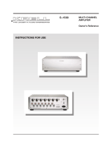
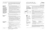
Figure 1 The KAV–280p Front Panel
MUTETAPE
POWER
STAND-BY
KAV–280p
3
1
2
4
5
B–1
S–1
S–2 S–3
7
11
6
9
10
8
Mode Indicators
8 Mute Button
9 Mute LED
Volume Adjustment
Functions
10 Level Knob
11 Front Panel Display
Power
1 Power Button
2 Power LED
3Stand-by LED
4 Infrared Sensor
Analog Devices
5 S-1, S-2, S-3, and
B-1 Buttons and LEDs
6Tape Button
7Tape LED

6 Krell KAV–280p
The front panel of the KAV–280p accesses power on and off,
analog input selections, volume control, and mute. The front panel
display shows the volume and balance levels, and Theater
Throughput status.
1 Power Button
Use this button to switch the KAV–280p between the stand-by and
the operational modes.
2 Power LED
The blue power LED illuminates when the KAV–280p is in the
operational mode. The power LED also flashes when any remote
control key is pressed.
3 Stand-by LED
The red stand-by LED illuminates when the KAV–280p is plugged
into a standard AC wall receptacle, indicating that the amplifier is
in the stand-by mode and ready to be switched to the operational
mode.
4 Infrared Sensor
The infrared sensor receives commands from the KAV–280p
remote control. For proper remote control operation, make sure
the infrared sensor is clear of any obstructions.
5 S-1, S-2, S-3, and B-1 Buttons and LEDs
Use these buttons to select a balanced analog source component
(B-1) via an XLR connector or a single-ended analog source com-
ponent (S-1, S-2, or S-3) via single-ended RCA connectors. The
selected button’s LED illuminates.
6 Tape Button
Use this button to playback pre-recorded tapes. You may also use
this button to compare the output signal of an analog tape recorder
to an audio source. See Tape Input and Output, on page 18.
7 Tape LED
The red tape monitor LED illuminates when the tape monitor is
activated. The LED does not illuminate when an audio source is
activated.
Front Panel Description
See Figure 1 on page 5
POWER
ANALOG
SOURCE
COMPONENTS
Front Panel
Functions

Krell KAV–280p 7
Front Panel Description continued
8 Mute Button
Use this button to interrupt the signal from the active source you
have selected. When the red mute LED (9) on the KAV–280p is
illuminated, there is no signal output.
To unmute the signal from the active source, press the mute but-
ton again. The red mute LED extinguishes.
9 Mute LED
The red mute LED illuminates when you have interrupted the signal
from the active source using the mute button (8) on the front panel
or mute key (25) on the remote.
10 Level Knob
The volume level knob adjusts the processor output level, which
is indicated numerically on the front panel display (11); range is
0-151.
To access the balance feature, use the remote control. See
Balance Keys, on page 13.
11 Front Panel Display
The front panel display shows volume levels, balance levels, and
Theater Throughput status.
MODE INDICATORS
VOLUME ADJUSTMENT
FUNCTIONS

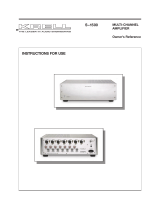
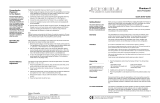
Figure 2 The KAV–280p Back Panel
50/60 Hz
OUT
R
MAIN OUT
MAIN OUT
L
L
RLRL
Preamplifier
TAPE OUT
RLRL
TAPE IN
RLR
LR
MADE IN USA
IN
12V
NO USER SERVICEABLE PARTS INSIDE
B–1
S–2
S–3
RC–5
IN
KAV–280p
12
13 14
16
17
18
20
19
21
15
Analog Inputs
12 Left and Right Balanced
Analog Inputs
13 Left and Right Single-ended
Analog Inputs
14 Left and Right Tape Inputs
Analog Outputs
15 Left and Right Tape Outputs
16 Left and Right Single-ended
Outputs
17 Left and Right Balanced
Outputs
Remote Connections
18 12 VDC Out and In
19 RC-5 In
Power
20 Line Fuse and Fuseholder
21 IEC Connector

Back Panel Description
See Figure 2 on page 8
Krell KAV–280p 9
The KAV–280p back panel provides connections for all inputs and
outputs, power on/off, and additional remote connections.
12 Left and Right Balanced Analog Inputs
The KAV–280p is equipped with one pair of balanced (B-1) inputs
via XLR connectors.
13 Left and Right Single-ended Analog Inputs
The KAV–280p is equipped with three pairs of single-ended (S-1,
S-2, or S-3) inputs via RCA connectors.
14 Left and Right Tape Inputs
The KAV–280p is equipped with a pair of single-ended tape inputs
via RCA connectors.
15 Left and Right Tape Outputs
The KAV–280p is equipped with a pair of single-ended tape
outputs via RCA connectors.
16 Left and Right Single-ended Outputs
The KAV–280p is equipped with a pair of single-ended preamplifier
outputs.
17 Left and Right Balanced Outputs
The KAV–280p is equipped with a pair of balanced preamplifier
outputs.
17 12 VDC Out
The KAV–280p is equipped with an output that sends 12 VDC
(12 V trigger) power on/off signals to other Krell components and
other devices that incorporate a 12 V trigger. This allows you to
turn other components on or off, or to and from stand-by, from the
KAV–280p. When the KAV–280p is switched between stand-by
and operate, it sends a signal from the 12 VDC Out that will switch
other components, allowing whole systems or parts of systems to
be easily coordinated.
ANALOG INPUTS
ANALOG OUTPUTS
BACK PANEL REMOTE
CONNECTIONS
Back Panel
Functions

Back Panel Description, continued
10 Krell KAV–280p
17 12 VDC In
The KAV–280p is equipped with an input that receives 12 VDC
(12 V trigger) power on/off signals from other Krell components
and other devices that incorporate a 12 V trigger. This allows you
to turn the KAV–280p on or off, or to and from stand-by, from other
components.
The 12 VDC output current is limited to 30 ma.
Consult the owner’s reference of the components used in a custom
installation to take full advantage of the remote capability of the
KAV–280p.
18 RC-5 In
The KAV–280p is equipped with an RC-5 input that makes custom
installation easy and secure by accepting baseband RC-5 input
commands from hardwired remote controllers.
19 Line Fuse and Fuseholder
The 50/60 Hz line fuse protects the KAV–280p in the event of a
component failure.
The fuseholder drawer houses two line fuses: one is functional
and one is a spare.
When the line fuse needs to be replaced, use the spare fuse provided.
Unplug the component before replacing the fuse. Use a 0.5A, slow-blow,
5 x 20 mm fuse for 100-120 VAC, or a 0.25A, slow-blow, 5 x 20 mm fuse
for 220-240 VAC.
20 IEC Connector
The connector is for use with the provided IEC standard 15 amp
power cord.
POWER
Note
Notes
BACK PANEL REMOTE
CONNECTIONS,
continued

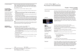
Figure 3 The KAV–280p Remote Control
Krell KAV–280p 11
22 23
25
24
26
27
28
Power
22 Power Key
23 Pre Key
Analog Functions
24 Analog Input Keys
25 Tape Key
Output Control
Functions
26 Mute Key
27 Vol (Volume) Keys
28 Bal (Balance) Keys
Note
The remote control keys listed above function with the KAV–280p. Other
keys on this remote control may activate other Krell components, for exam-
ple, other compact disc players. Consult the Krell owner’s reference manual
for each component to review the remote control capabilities for each Krell
component.

Remote Control Description
See Figure 3 on page 11
12 Krell KAV–280p
The KAV–280p remote control uses one CR2025 lithium battery,
which is included with the shipment.
To open the battery compartment on the back of the remote
control:
1. Place the remote face down on the table.
2. Use your thumbnail or a small jeweler’s or eyeglass screw-
driver to move the small switch toward the center of the
remote, while using your index fingernail or screwdriver to pull
down gently on the slot to the right of the switch. The battery
compartment will slide out.
Do not use a knife or other sharp objects to open the battery compart-
ment; they will scratch the remote control finish.
3. Place the battery, positive side up, in the battery tray.
4. Slide battery compartment back into the remote until you hear
a click.
The remote control is ready for operation.
Replace battery when remote control function becomes intermittent.
Remove battery if the remote control is not used for a long period of time.
Battery leakage can damage the remote control.
The KAV–280p remote control accesses all preamplifier functions.
A description of the remote control keys that activate the
KAV–280p follows.
When you press a function key on the remote, the blue power LED (2) will
flash. (The LED will flash repeatedly if a key is held down.)
22 Pwr (Power) Key
Use this key to switch the KAV–280p between the stand-by and
the operational modes.
Note
Notes
Note
Battery
Installation
and
Removal
Remote Control
Functions
POWER

Remote Control Functions continued
Krell KAV–280p 13
23 Pre Key
Use this key to activate the KAV–280p remote and access other pre-
amplifier commands. You can then access preamplifier commands
until you press a different activation key, for example the CD key to
access commands for a Krell compact disc player. To return to the
preamplifier commands, press the pre key again. You only need to
press an activation key once. The remote “remembers” whether the
pre key or the CD key has been pressed most recently.
24 Analog Input Keys
Use these keys to select a balanced input (B-1) or single-ended
input (S-1, S-2, or S-3). The selected input LED on the front panel
illuminates.
25 Tape Key
Use this key to monitor the output signal of a three-head analog
tape recorder, compared to the output signal from an audio
source, when making a recording. See Tape Input and Output,
on page 18. The red tape monitor LED on the front panel illumi-
nates when the tape monitor is activated.
26 Mute Key
Use this key to interrupt the signal from the active source you
have selected. When the red mute LED (9) on the KAV–280p is
illuminated, there is no signal output.
To unmute the signal from the active source, press the mute key
again. The red mute LED extinguishes.
27 Vol (Volume) Keys
Press these keys to adjust the amplifier output level, which is indi-
cated numerically on the front panel display (11); range is 0-151.
28 Bal (Balance) Keys
Use these keys to shift the balance to the left or the right channel,
in 1 dB increments. Balance level is indicated in the front panel
display (11).
ANALOG FUNCTIONS
OUTPUT CONTROL
FUNCTIONS
POWER, continued

Remote Control Functions continued
14 Krell KAV–280p
To access and display balance, push either the “L” or the “R” bal-
ance key on the remote. The front panel display indicates the bal-
ance setting. After 3 seconds of inactivity or after a volume adjust-
ment, the front panel display reverts to the volume setting.
The front panel display indicates:
– C –
when the balance is centered. If the balance is not centered, the
front panel display indicates balance right or left of center, and
how much the balance is off center, on a scale of 1 (slightly off
center) to 5 (completely on one side).
Example: A display of:
– – 3
means that the balance is moderately right of center. A display of:
5 – –
means the balance is severely left of center.
The remote control keys listed above function with the KAV–280p. Other
keys on this remote control may activate other Krell components, for
example, compact disc players. Consult the Krell owner’s reference man-
ual for each component to review the remote control capabilities for each
Krell component.
Analog Functions,
continued
Note

Krell KAV–280p 15
Krell recommends using balanced interconnect cables. Balanced
interconnect cables not only can minimize sonic loss but are also
immune to induced noise, especially with installations using long
cables. Balanced connections have 6 dB more gain than single-
ended connections. When level matching is critical, keep this gain
value in mind.
Follow these steps to connect the KAV–280p to your system.
1. Make sure all power sources and components are off before
connecting inputs and outputs.
2. Neatly organize the wiring between the KAV–280p and all sys-
tem components. Separate AC wires from audio cables to
prevent hum or other unwanted noises from being introduced
into the system.
3. Connect the outputs of your source components to the inputs
on the KAV–280p.
The KAV–280p has one pair of balanced outputs via XLR con-
nectors and one pair of single-ended outputs via RCA connec-
tors. Both balanced and single-ended outputs are active at all
times, allowing simultaneous connections to separate ampli-
fiers or separate systems.
Do not connect both outputs to a single stereo amplifier at one time.
4. Connect the outputs of the KAV–280p to the inputs of your power
amplifier.
The KAV–280p is equipped with one balanced input via XLR
connectors (B-1), three single-ended inputs via RCA connectors
(S-1, S-2, and S-3), and one tape input via RCA connectors.
The B-1, S-1, S-2, and S-3 inputs can be configured for Theater
Throughput. See Configuring the KAV–280p for Theater
Throughput, on page 19.
5. Plug the AC cord into the IEC connector (21) on the back
panel of the KAV–280p. Plug the remaining end into the AC
wall receptacle. The red stand-by LED (3) illuminates, and the
front panel display will flash “
– – –
” for 10 seconds. When the
display stops flashing, the preamplifier is ready to use.
Connecting the KAV–280p
to Your System
USING BALANCED
CONNECTIONS
Connection
Steps
Note

16 Krell KAV–280p
Pin 1 Shield (ground)
Pin 2 Non-inverting (hot) (0°)
Pin 3 Inverting (cold) (180°)
RC-5 IN
This input accepts baseband RC-5 input commands. It facilitates
custom installations by allowing the KAV–280p to be controlled via
hard-wired signals from various remote devices.
12 VDC REMOTE POWER IN / OUT
The input accepts 12 Volt power on/off signals from other Krell
components and the output sends 12 volt power on/off signals to
other Krell components, as well as to other devices that incorpo-
rate a 12-Volt power on/off trigger input.
This feature allows enables the remote turn on/off of other compo-
nents when the KAV–280p is powered on/off.
Consult the owner’s reference of any device used in a custom installation
to take full advantage of the remote capability of the KAV–280p.
Connecting the KAV–280p to Your System
continued
Pin assignments for the
XLR connectors
Additional
Connections
Note
/