Muskoka MEF2367CBWLG Operating instructions
- Category
- Fireplaces
- Type
- Operating instructions
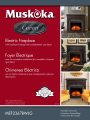
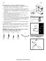
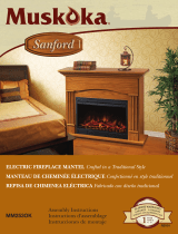
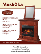
Muskoka MEF2367CBWLG The Muskoka MEF2367CBWLG is a customizable electric fireplace mantel with a variety of features that allow you to enjoy the ambiance of a fire without the mess and hassle of a traditional wood-burning fireplace.
The mantel is constructed from durable materials and features a realistic flame effect that can be adjusted to suit your preferences. It also comes with a remote control so you can easily operate the fireplace from the comfort of your chair.
In addition to its aesthetic appeal, the Muskoka MEF2367CBWLG is also a functional piece of furniture. It includes a built-in storage shelf that is perfect for storing firewood, kindling, or other fireplace accessories. The mantel also has a built-in heater that can be used to supplement your home's heating system on cold days.


-
 1
1
-
 2
2
-
 3
3
-
 4
4
-
 5
5
-
 6
6


Muskoka MEF2367CBWLG Operating instructions
- Category
- Fireplaces
- Type
- Operating instructions
Muskoka MEF2367CBWLG The Muskoka MEF2367CBWLG is a customizable electric fireplace mantel with a variety of features that allow you to enjoy the ambiance of a fire without the mess and hassle of a traditional wood-burning fireplace.
The mantel is constructed from durable materials and features a realistic flame effect that can be adjusted to suit your preferences. It also comes with a remote control so you can easily operate the fireplace from the comfort of your chair.
In addition to its aesthetic appeal, the Muskoka MEF2367CBWLG is also a functional piece of furniture. It includes a built-in storage shelf that is perfect for storing firewood, kindling, or other fireplace accessories. The mantel also has a built-in heater that can be used to supplement your home's heating system on cold days.
Ask a question and I''ll find the answer in the document
Finding information in a document is now easier with AI
Related papers
-
Muskoka MEF253OK User manual
-
-
-
-
-
-
-
-
Muskoka Electric Fireplace Mantel MEF2808CHG User manual
-
Other documents
-
Kmart 43109029 User manual
-
Imperial IMP 50-4009 Operating instructions
-
Home Decorators Collection 0561500610 Installation guide
-
 Greenway Home Products MEF253OK User manual
-
 Franklin Sports 12384F4 User manual
-
 Greenway Home Products MM281MCH User manual
-
 Greenway Home Products Muskoka MM289CW User manual
-
-
 Greenway Home Products MM281CBL User manual
-
 Greenway Home Products MM284SOK User manual


