Page is loading ...

E2010 CCN 99713075
(800) 276-4658 D FAX (800) 266-7016
INGERSOLL RAND COMPANY LTD
P.O. BOX 151 D ONE ARO CENTER D BRYAN, OHIO 43506-0151
OPERATOR’S MANUAL
67072
RELEASED: 3-7-06
REVISED: 1-05-10
(REV. G)
67072 CYCLE CONTROLLER
(PNEUMATIC COUNTDOWN TYPE)
FOR 3/8”, 1/2” & 1” DIAPHRAGM PUMPS WITH 1/4” AIR INLETS
67072
CYCLE CONTROLLER RETRO-FIT KIT.
This kit includes additional parts to do a field retro-fit to standard pumps
models as follows:
3/8” -- PD03P-XXX-XXX (refer to page 3).
1/2” -- 66605X-XXX, PD05P-XXX-XXX, PD05P-XXX-XXX-B and
PD05R-XXX-XXX-B (non-metallic air motor)(refer to page 3).
1” -- 6661A
X-XXX-C, 6661BX-XXX-C (refer to page 3), 66610X-
XXX-C, 66611
X-XXX-C, 66612X-XXX-C and 66613X-XXX-C
(refer to page 4).
• 3/8” and 1/2” Pumps - Pilot plug and replacement “O” ring(s).
• 1” Pumps - Screws, plate, gaskets, & template for leg modification.
GENERAL DESCRIPTION
The diaphragm pump Cycle Controller Assembly provides logic control
for preset dispensing.When installed on a diaphragm pump, it can moni-
tor the diaphragm pump pulse or cycle and allow the user to accurately
control the number of cycles the pump will produce. This will effectively
allow a preset and repeatable amount of material to be dispensed
through the pumping system.
Pumps used with this counter assembly must be retrofitted with special
parts. These special parts will allow the pump to output a pilot air signal
which is needed to trigger the counter.
The controller assembly, with 1/4” N.P.T. inlet / outlet, includes a pre-as-
sembled countdown counter, palm operated valve, bracket, tubing and
an air regulator with air pressure gauge.
NOTE: This kit is intended to be attached directly to the pump air inlet.
Mounting it a distance from the pump could result in an air pressure drop
in the pilot signal to the counter and may affect the accuracy.
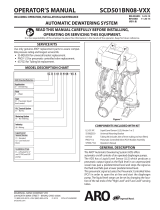
SCHEMATIC VIEW
REGULATOR
R37121- 100
AIR
INLET
PALM
VALVE
E212HP
PUMP
SIGNAL
COUNTER
59802
-5
-3
4
2
P
A
Z
Y
AIR
OUTLET
GAUGE
Figure 1
OPERATION
To determine the number of cycles needed to get the desired output, use
the following formula: Divide the amount of material desired by the dis-
placement per cycle to get the counter setting that is needed (refer to the
pump manual).
NOTE: For best results, operate the pump at 30 - 90 p.s.i. (2.1 - 6.2
bar). Fluctuations in the air pressure can affect the displacement per
cycle. Once the desired displacement is achieved, keep the air pressure
as constant as possible.
BASIC OPERATION
1. Connect air to pump.
2. Set cycle count: Hold the reset button down while entering a new
number of cycles on the counter.
3. Press the palm button to start the cycle.
4. The pump will automatically shut off and reset to the count originally
set.
67020
CYCLE CONTROLLER
SEE ADDITIONAL PARTS
ON FOLLOWING PAGES

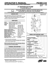
67072Page2of4
93950 Bracket
59802 Counter
Y8-104-C Screw (2)
1/4 - 18 P.T.F. Short
Air Inlet
(supply
air 120 p.s.i.
maximum)
1/4 - 18 N.P.T.F. -1 − Outlet
(air supply to pump)
Available in bulk quantities only (5/32" o.d. x 100’ long) − pn 94981-XXX-X.
Available in bulk quantities only (10).
E212HP Palm Valve Assembly
20311-2 Breather Vent (2)
29850 Gauge
R37121-100 (104467) Regulator
59756-4 90 Elbow (3)
94981-X Tube
(5/32" o.d. x 4" long)
59756-154 90° Elbow
75364 Swivel Union
1950 Nipple (2)
1/8 - 27 N.P.T. − Air Signal (from the pump pilot)
94981-X Tube
(5/32" o.d. x 6" long)
94981-X Tube
(5/32" o.d. x 10" long)
94981-X Tube
(5/32" o.d. x 6" long)
67072 CONTROLLER ASSEMBLY
Figure 2

Page3of4
67072
3/8” AND 1/2” DIAPHRAGM PUMP CONTROLLER INSTALLATION
3/8” AND 1/2” DIAPHRAGM PUMPS (see figure 3)
NOTE: Refer to the pump Operator’s Manual.
1. Remove the four long valve block retaining bolts.
2. Remove the 93086 or 96352 plug from the air motor major valve.
3. Models 66605X-X and PD05P-X-X: Install the new 93909 plug (with
the threaded hole), use the new Y325-125 “O” ring included in kit.
Models PD03P-X-X, PD05P-X-X-B and PD05R-X-X-B: Install the
new 96462 plug (with the threaded hole), use the new Y325-29 “O”
rings included in kit.
4. Reassemble the valve and replace the major valve bolts, torque to
15 - 20 in. lbs (1.7 - 2.3 Nm).
5. Remove the tubing from the 90_ elbow and install the 59756-4 90_
tubing elbow into the new pilot port.
6. Attach the kit to the pump inlet as shown and re-attach the tube to the
59756-4 90_ elbow.
1” NON-METALLIC DIAPHRAGM PUMP CONTROLLER INSTALLATION
1” NON-METALLIC DIAPHRAGM PUMPS ONLY (see figure 4)
NOTE: Refer to the pump Operator’s Manual.
1. Remove four major valve cap screws and plate on the air inlet side of
the pump.
2. Remove 92878 gasket.
3. Replace the old 92878 gasket with new 92878 gasket provided in
the kit.
4. Install the new 93911 adapter plate with the 1/8 - 27 N.P.T.F - 1 ta-
pered threads outward, secure the plate with four screws and wash-
ers.
5. Remove the tubing from the 90_ elbow and assemble the 59756-4
90_ tubing elbow into the adapter plate. NOTE: The elbow cannot
be installed if the plate is reversed.
6. Attach the kit to the pump inlet as shown and re-attach the tube to the
59756-4 90_ elbow.
Controller
59756-4 90° Elbow
Replace existing plug with new 93909/
96462 pilot plug and Y325-125 / Y325-29
replacement “O” ring(s).
1/2" Diaphragm Pump
Figure 3
VIEW OF 1/2" NON-METALLIC DIAPHRAGM PUMP SHOWING ASSEMBLY OF 67072 CYCLE CONTROLLER
Controller
1” Diaphragm Pump
93911 Adapter Plate
Major Valve Cap Screws
Gasket
Figure 4
59756-4 90 Elbow
CROSS SECTION OF 1" NON-METALLIC DIAPHRAGM PUMP
SHOWING ASSEMBLY OF 67072 CYCLE CONTROLLER

67072Page4of4
1” METALLIC DIAPHRAGM PUMP CONTROLLER INSTALLATION
1” METALLIC DIAPHRAGM PUMPS ONLY (see figure 5)
NOTE: Refer to the pump Operator’s Manual.
1. On the air inlet side of the pump, remove the four Major Valve cap
screws, 92003 leg and 92878 gasket.
2. The leg of a 1” metallic diaphragm pump must be modified. Use the
93913 template included as a guide (drill a 1/2” hole).
3. Replace the old 92878 gasket with new 92878 gasket provided in
the kit.
4. Position the modified leg.
5. Place the 92004 gasket on the leg.
6. Install the 93911 adapter plate with the 1/8 - 27 N.P.T.F. - 1 tapered
threads outward, secure the plate with four screws and lockwash-
ers. NOTE: The elbow cannot be installed if the plate is reversed.
7. Remove the tubing from the 90_ elbow and assemble the 59756-4
90_ tubing elbow into the adapter plate.
8. Attach the kit to the pump inlet as shown and re-attach the tube to the
59756-4 90_ elbow.
PN 97999-596
90 Tubing Elbow
Signal Tube
Figure 5
1" METALLIC DIAPHRAGM PUMP
REASSEMBLY ORDER
1. 92878 Gasket
2. 92003 Modified Leg (with new hole drilled by installer)
3. 92004 Gasket
4. 93911 Adapter Plate
5. Lockwasher (4)
6. Y6-45-C Screw (4)
(1/4" - 20 x 1")
Air Inlet
67072 Controller
1" Diaphragm Pump
93913 TEMPLATE
FOR USE WITH
1" METALLIC LEG
ALIGN THE FOUR 9/32" DIA. TEMPLATE HOLES WITH THE
FOUR LEG BOLT HOLES.
ALINEE LOS CUATRO ORIFICIOS DE 9/32" DE DIÁMETRO
DE LA PLANTILLA CON LOS CUATRO ORIFICIOS DE LOS
PERNOS DE LAS CUATRO PATAS.
ALIGNER LES QUATRE TROUS DU GABARIT DE 9/32" DE
DIAMÈTRE AVEC LES QUATRE TROUS DE BOULON DE LA
PATTE.
DRILL A .500" DIA. HOLE THROUGH THE LEG HERE.
PERFORE AQUÍ UN ORIFICIO DE .500" DE DIÁMETRO A
TRAVÉS DE LA PATA.
PERCER ICI UN TROU DE 0,500" DE DIAMÈTRE DANS LA
PATTE.
P/N 93913
/