Page is loading ...

1
Thank you for purchasing this 4-Port RS422/485 Serial PCI Express
(PCIe) Card. It is a universal add in card that connects to a PC
or server via the PCIe Bus, providing high-speed serial
connectivity. The serial ports are fully compatible with
RS422/485 standard by the bundled Serial COM port drivers.
Each port can be set in any mode (RS485 2-wire, RS485 4-wire
and RS422) and operate simultaneously.
There is an optional model supports Isolation and ESD
protection feature. It provides an ideal solution for most critical
applications.
4-Port R422/485 Serial PCIe Card
w/ Octopus Cable
Installation Guide
1. Introduction
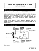
2. Connector Layout
JP1: S1~S4
Mode Selector
JP2: S1~S4
RS485 TXD
Control
J2: Factory
Use Only
JP15:
S3 Terminator
Enable/Disable
JP16:
S4 Terminator
Enable/Disable
J3: DB44F Connector, to DB44M-to-DB9MX4 Octopus Cable
Low Profile Bracket
(optional)
Normal Bracket
JP3: S1~S4
RS485 Echo
Control
JP14:
S2 Terminator
Enable/Disable
JP13:
S1 Terminator
Enable/Disable

4-Port 422/485 Serial PCIe Card
2
DB44F-to-DB9MX4 Octopus Cable:
Features:
Provides 4 RS422/485 Serial Ports over PCI Express Slot
Provides 4 DSUB-9 Connectors with the Octopus Cable
Fully Compliant with PCI Express Base Specifications, Revision 1.1
Supports Serial Baud Rate up to 921.6Kbps
Support 4-wire RS422/485 and 2-wire RS485 Modes
Supports 5, 6, 7, 8 and 9-bit Data Framing
Supports 1, 1.5 and 2 Stop Bits.
128-byte Deep FIFO per Transmitter and Receiver
Supports Low Profile Form Factor with Optional Low Profile Bracket
Optional Model Supports 2,500Vrms Isolation and 15KV ESD
Protection
Supports Win98, Me, XP, CE, Win2K, 2003, Vista, Win 7 and Linux
There are 4 groups of the jumpers to set modes, Terminator, RS485
Echo control, and RS485 TXD control settings for each port. Each group
controls the settings for port 1 (S1) to port 4 (S4) respectively.
3. Jumper Settings
P4
Port 3 (DB9 male)
To DB44 Male Connector
Port 1 (DB9 male)
Port 2 (DB9 male)
Port 4 (DB9 male)
P3
P4
P2
P1

4-Port RS422/485 Serial PCIe Card
3
Mode Selection Jumpers: JP1 (for S1~S4)
Termination Resistor Enable/Disable Jumpers: JP13~JP16 (for
S1~S4)
Echo or No Echo Selection Jumpers: JP3 (for S1~S4)
TXD Control Selection Jumpers: JP2 (for S1~S4)
1.
Mode Settings:
JP1 (for S1~S4)
Description
RS485 2-wire mode
(Default)
RS485 4-wire mode
RS422 mode
2. Termination Resistor Enable/Disable: This jumper
enables/disables the 120 Ohm termination resistor between
DATA+ and DATA- of the RS485 transceiver:
JP13~JP16 (for S1~S4)
Description
485-2W
485-4W
422
485-2W
485-4W
422
485-2W
485-4W
422

4-Port 422/485 Serial PCIe Card
4
Termination Resistor Disabled
(Default)
Termination Resistor Enabled
3.
Echo or No Echo Settings: JP3 (for S1~S4) This jumper is to
set the transmission data will be echoed back or not.
The
Echo mode is useful for the application program to detect if the
RS485 bus has collision. If the echoed data was not equal to the
transmitted data, then the bus was in a collision. This setting only
affects the RS485 2-wire mode. It doesn’t affect RS485 4-wire,
and RS422 modes.
JP3 (for S1~S4)
Description
No echo data
(Default)
Transmission data will be echoed
4. TXD Control Selector: JP2 (for S1~S4):
This jumper is used to select the control signal for the transmitter
buffer in RS485 2-wire mode. There are 2 settings are selectable,
ON
OFF
OFF
ON
ECHO
OFF
ON
ECHO
ON
OFF

4-Port RS422/485 Serial PCIe Card
5
one is “MAN” (manually) the other one is “AUT” (automatically,
factory default), please keep it at “AUT” in all cases.
JP2 (for S1~S4)
Description
TXD Control is Automatic
(Default)
TXD Control is Manual
(Needs to be Configured
Manually in the Device
Manager)
5. Factory Use Only Connector (J2):
This connector is only used for factory production purpose, please
don’t install any jumper or cable on it!
1. Turn the system power OFF before installation!
2. Remove the chassis cover from your computer
3. Locate an unused PCI Express slot (typically smaller than PCI) and
remove the corresponding slot cover from computer chassis.
4. Plug the RS422/485 PCIe card to the unused PCI Express
expansion slot and attached the I/O card bracket to the
computer chassis screw.
5. Put the chassis cover back on the computer.
6. Install the Octopus Cable, connect the RS422 or RS485 Devices to
the DB9M Connectors of the cable.
7. Turn ON the power of your computer and peripherals.
8. Proceed with Software Driver Installation.
4. Installing the RS422/485 PCIe Card
5. Software Installation
485TR
MAN
AUT
485TR
MAN
AUT

4-Port 422/485 Serial PCIe Card
6
NOTE:
PLEASE DO NOT LET WINDOWS AUTO SEARCH THE DRIVERS ON THE CD, it
will cause problems because the INF files will be conflict in this case.
Instead, please browse to the correct location (folder) manually to
make sure the correct drivers are chosen and installed correctly.
The drivers of the RS422/485 PCIe card for each Operating System
were shipped in the following different folders on the driver CD:
When the Windows detects the PCIe card, it will invoke its Installation
Wizard:
Drivers are in each
corresponding folder

4-Port RS422/485 Serial PCIe Card
7
Note: For Windows 2000 installation, we recommend you to choose “Install
from a list or specific location (Advanced)” from the following menu, then browse
to the correct driver location (\IO\OXFORD2\2000\...) for Windows 2000. It will prevent
from the Windows 2000 searching wrong drivers.

4-Port 422/485 Serial PCIe Card
8
DB9-Male Pin Assignment:
RS422 Cable Wiring:
6. RS422/485 Pin Assignments and Cable Wiring
DB9 (RS422, PCIe Card)
1 TXD-
2 TXD+
3 RXD+
4 RXD-
5 GND
(RS422 Device)
1 TXD-
2 TXD+
3 RXD+
4 RXD-
5 GND
NC = No connection
1 5
6 9
9 Pins Signal
1 TXD- (DATA-)
2 TXD+ (DATA+)
3 RXD+
4 RXD-
5 GND
6 NC
7 NC
8 NC
9 NC
Check Windows Version
Showed in the folder here:
XP32 in this example

4-Port RS422/485 Serial PCIe Card
9
RS485 (2-wire) Cable Wiring:
Power requirements: 5V DC, 800mA (max)
Operating temp.: 0 to 55
°C (32 to 131°F)
Operating humidity: 5 to 95% RH
7. Environmental Specifications
DB9 (485, PCIe Card)
1 DATA-
2 DATA+
3 NC
4 NC
5 GND
(RS485 Device)
1 DATA-
2 DATA+
3 NC
4 NC
5 GND
/