Robbins AHS1100 Installation guide

Type
Installation guide
WARNING:
E
XISTING IN-PLACE RESILIENT FLOOR COVERING AND ASPHALTIC
A
DHESIVES. DO NOT SAND, DRY SWEEP, DRY SCRAPE, DRILL, SAW, BEADBLAST, OR
M
ECHANICALLY CHIP OR PULVERIZE EXISTING RESILIENT FLOORING, BACKING, LINING
F
ELT, ASPHALTIC “CUTBACK” ADHESIVE, OR OTHER ADHESIVE.
T
hese existing in-place products may contain asbestos fibers and/or crystalline silica.
Avoid creating dust. Inhalation of such dust is a cancer and respiratory tract hazard.
S
moking by individuals exposed to asbestos fibers greatly increases the risk of serious bodily harm.
Unless positively certain that the existing in-place product is a non-asbestos-containing material, you must
p
resume it contains asbestos. Regulations may require that the material be tested to determine asbestos content
a
nd may govern removal and disposal of material.
S
ee current edition of the Resilient Floor Covering Institute (RFCI) publication Recommended Work Practices for
R
emoval of Resilient Floor Coverings
f
or instructions on removing all resilient floor covering structures or contact
your retailer or Armstrong Flooring Inc. 1 800 233 3823.
T
he floor covering or adhesive in this package does NOT contain asbestos.
RECOMMENDED CLEANER: Bruce
®
Hardwood &
Laminate Floor Cleaner
NETTOYANTS RECOMMANDÉS : Nettoyant pour planchers en bois franc et
laminé Armstrong
®
Flooring
LIMPIADOR RECOMENDADO: Limpiador para pisos de madera dura y
laminados Armstrong
®
Flooring
ATTENTION INSTALLERS
Sawing, sanding and machining wood products can produce wood dust. Airborne wood dust can
cause respiratory, eye and skin irritation. The International Agency for Research on Cancer (IARC)
has classified wood dust as a nasal carcinogen in humans.
Precautionary Measures: If power tools are used, they should be equipped with a dust collector. If high dust
levels are encountered, use an appropriate NIOSH-designated dust mask. Avoid dust contact with eye and skin.
First Aid Measures in Case of Irritation: In case of irritation, flush eyes or skin with water for at least
15 minutes.
If you have any technical or installation questions, or to request a Material Safety Data Sheet,
please call 1 800 233 3823 or visit www.floorexpert.com, our technical website.
CAUTION: WOOD DUST
I. GENERAL INFORMATION
Owner/Installer Responsibility
Beautiful hardwood floors are a product of nature and therefore, not perfect. Our hardwood floors are manufactured in
accordance with accepted industry standards, which permit grading deficiencies not to exceed 5%. These grading
deficiencies may be of a manufacturing or natural type. When flooring is ordered, 5% must be added to the actual square
footage needed for cutting and grading allowance (10% for diagonal installations).
The owner/installer assumes all responsibility for final inspection of product quality. Inspection of all flooring should
be done prior to installation. Carefully examine flooring for color, finish and quality before installing it. If material is not
acceptable, do not install it. Contact the seller immediately.
Prior to installation of any hardwood flooring product, the owner/installer must determine that the job-site environment
and the sub-surfaces involved meet or exceed all applicable standards. Recommendations of the construction and
materials industries, as well as local codes, must be followed. These instructions recommend that the construction
a
nd subfloor be clean, dry, stiff, structurally sound and flat. The manufacturer declines any responsibility for job failure
resulting from, or associated with, subfloor and substrates or job-site environmental deficiencies.
Prior to installation, the owner/installer has final inspection responsibility as to grade, manufacture and factory finish.
The installer must use reasonable selectivity and hold out or cut off pieces with deficiencies, whatever the cause.
Should an individual piece be doubtful as to grade, manufacture or factory finish, the installer should not use the piece.
Use of stain, filler or putty stick for touch-up and appropriate products for correcting subfloor voids is accepted as part
of normal installation procedures.
Subfloor Conditions
CLEAN – Subfloor must be free of wax, paint, oil, sealers, adhesives and other debris.
LEVEL/FLAT – Within 3/16
ʺ i
n 10
ʹ (
5 mm in 3 m) and/or 1/8
ʺ i
n 6
ʹ (
3 mm in 2 m). Sand high areas or joints. Flatten
low spots with a maximum 6 layers of 15# builders felt, plywood or shims (not leveling compounds).
DRY Check and document moisture content of the subfloor with the appropriate moisture test. Install moisture
retardant materials if needed or desired. (See plank installation note.) Moisture retardant materials must meet
minimum perm standards of 3 > 50 ASTM D4869-88, Type I or F.S. UU-B-790a, Type I, Grade D, Style 1a. Most asphalt
saturated papers, #15 felt or Grade D kraft paper meet this perm rating. Common brown kraft builder paper and red
rosin generally do not qualify as vapor retarders. Concrete subfloors must be a minimum of 30 days old before testing
begins.
STRUCTURALLY SOUND – Nail or screw any areas that are loose or squeak. Wood panels should exhibit an adequate
fastening pattern, glued/screwed or nailed as system requires, using an acceptable nailing pattern. Typical: 6
ʺ (15 cm)
along bearing edges and 12
ʺ (31 cm) along intermediate supports. Flatten any swollen edges as necessary. Replace
any water-damaged, swollen or delaminated subflooring or underlayments.
NOTE: Avoid subfloors with excessive vertical movement. Optimum performance of hardwood floor covering products
occurs when there is little horizontal or vertical movement of the subfloor. If the subfloor has excessive vertical
movement (deflection) before installation of the flooring, it is likely it will do so after installation of the flooring is
complete.
Subfloors with Radiant Heat
NOTE: Do not install this product over Subfloors with Radiant Heat.
Tools & Accessories Needed
NOTE: IT IS EXTREMELY IMPORTANT TO USE THE PROPER ADAPTERS, FACE PLATES, AS WELL AS STAPLES
OR CLEATS. IMPROPER FASTENERS, MACHINES AND AIR PRESSURE CAN CAUSE SEVERE DAMAGE. THE
MANUFACTURER OF THIS FLOORING PRODUCT IS NOT RESPONSIBLE FOR DAMAGE CAUSED BY USE OF IMPROPER
TOOLS OR MISUSE.
Chalk line & chalk • Recommended hardwood flooring cleaner • Nail set • Tape measure • Hammer
Electric power saw • NIOSH-designated dust mask • Electric drill and bits
Compressor and hose w/in-line regulator for pneumatic tools
“Blind’ fastening machine for 3/4
ʺ (19 mm) flooring (see note below)* w/1-1/2ʺ or 2ʺ (4–5 cm) fasteners
Pneumatic finish nailer with 1-1/ 2
ʺ or 2ʺ (4–5 cm) nails • 6-8d finish nails
Moisture meter (wood, concrete or both) Broom Hand saw or jamb saw
Eye protection • Transition and wall moldings
Urethane construction adhesive for floors wider than 4
ʺ (10 cm)
*Use a “Blind” nailing machine designed for installing 3/4
ʺ (19 mm) hardwood flooring using
staples or cleats. The nailing machine MUST HAVE a protective foot attachment to prevent
edge bruising and finish damage. Use one of the following: Stanley Bostitch (multiple
models) with M-4 foot, Powernail (multiple models) with NailerShoe, Primatech (multiple
models) with Trak-Edge.
III. SUBFLOOR/UNDERLAYMENT REQUIREMENTS
NOTE: Solid hardwood flooring can be fastened to most existing flooring materials providing they can be penetrated with the
fastener and the subfloor/underlayment materials meet or exceed the recommended subfloor/underlayment requirements.
Laminated rosin paper or 15# builders felt (tar paper) acts as a moisture retarder and may be used to reduce movement caused
by changes in subfloor moisture, thereby reducing cupping and warping. (This is especially helpful over crawl spaces and
basements.) In addition, the use of these materials can give the flooring a more solid feeling, reduce sound transfer, prevent
noise caused by minor irregularities and debris, and make it easier to slide the hardwood together across the surface of the
subfloor. Kraft paper may be used to make installation easier but DOES NOT serve any other purpose.
Wood Subfloors and Underlayment
General: The wood subflooring materials must not exceed 13% moisture content. Using a reliable wood moisture meter,
measure the moisture content of both the subfloor and the hardwood flooring to determine proper moisture content. The
difference between the moisture content of the wood subfloor and the hardwood flooring must not exceed 4% for strip
and 3% for plank flooring. When installing parallel to the floor joists it may be necessary to stiffen the subfloor system
by installing an additional minimum of 3/8
ʺ (9.5 mm) approved wood underlayment. Applicable standards and
recommendations of the construction and materials industries must be met or exceeded.
NOTE: As flooring manufacturers, we are unable to evaluate each engineered joist/subfloor system. Spacing and spans,
as well as their engineering methods, are the responsibility of the builder, engineer, architect or consumer who is better
INSTALLATION INSTRUCTIONS
SOLID WOOD FLOORING
3
4
ʺ (19 mm) Strip and Plank
M
ECHANICALLY FASTENED; STAPLE, NAIL OR
C
LEAT APPLICATIONS
MODE D’INSTALLATION
C
OUVRE-PLANCHER EN
BOIS MASSIF
L
ame et planche de 19 mm (
3
4
p
o)
P
OUR POSES AVEC ATTACHES MÉCANIQUE,
AGRAFES, À CLOUER OU À TASSEAU
INSTRUCCIONES DE INSTALACIÓN
PISOS DE MADERA DURA
Tablones y listones de
3
4
ʺ
FIJACIÓN MECÁNICA; CON GRAPAS, CLAVOS
O
TABLILLAS
For complete warranty information call 1 800 233 3823 or visit armstrongflooring.com.
II. PREPARATION
Storage and Handling
Solid hardwood flooring should be stored in the environment in which it is expected to perform. Deliver the materials to
an environmentally controlled site. The wood subflooring materials must not exceed 13% moisture content. Using a
reliable wood moisture meter, measure and document the moisture content of both the subfloor and the hardwood
flooring to determine proper moisture content. The difference between the moisture content of the wood subfloor and
the wood flooring must not exceed 4% (3% for plank). Acclimate the hardwood flooring on or off the job, as necessary,
to meet these requirements. Store in a dry place, being sure to provide at least a four-inch air space under cartons which
are stored upon “on-grade” concrete floors. Flooring should not be delivered until the building has been enclosed, with
windows and doors in place, and until cement work, plastering and all other “wet” work is completed and dry. Concrete
should be at least 60 days old.
Job-Site Conditions
The building should be enclosed with all outside doors and windows in place.
All concrete, masonry, framing members, drywall, paint and other “wetwork
should be thoroughly dry. The wall coverings should be in place and the
painting completed, except for the final coat on the base molding. When
possible, delay installation of base molding until flooring installation is
complete. Basements and crawl spaces must be dry and well ventilated.
Exterior grading should be complete with surface drainage, offering a minimum
drop of 3
ʺ in 10ʹ (7.6 cm in 3.05 m), to direct flow of water away from the
structure. All gutters and downspouts should be in place.
Solid hardwood flooring may be installed on- or above- grade level. Do not
install in full bathrooms. Installation of a suitable subfloor is required over
concrete.
Crawl spaces must be a minimum of 18
ʺ (46 cm) from the ground to the
underside of the joists. A ground cover of 6–20 mil black polyethylene film is
essential as a vapor barrier with joints lapped 6
ʺ (15 cm) and sealed with
moisture resistant tape. The crawl space should have perimeter venting equal
to a minimum of 1.5% of the crawl space square footage. These vents should
be properly located to foster cross ventilation (Figure 1). Where necessary, local
regulations prevail.
Permanent air conditioning and heating systems should be in place and operational. The installation site should have
a consistent room temperature of 60–75° F (16–24° C) and humidity of 35–55% for 14 days prior to and during
installation and until occupied.
Figure 1
2nd Floor
(above ground level)
1st Floor
(ground level)
Basement
(below ground level)
Soil Line
RECOMMENDED CLEANER: Armstrong
®
Flooring
Hardwood & Laminate Floor Cleaner
RECOMMENDED CLEANER: Armstrong Flooring
H
ardwood & Laminate Floor Cleaner
NETTOYANTS RECOMMANDÉS : Nettoyant pour planchers en bois franc et
l
aminé Armstrong Flooring
LIMPIADOR RECOMENDADO: Limpiador para pisos de madera dura y
l
aminados Armstrong Flooring
NETTOYANTS RECOMMANDÉS : Nettoyant pour planchers en bois franc et
laminé Bruce
®
LIMPIADOR RECOMENDADO: Limpiador para pisos de madera dura y
laminados Bruce
®
Protective Foot
able to evaluate the expected result based on site-related conditions and performance. The general information provided
below describes common, non-engineered joist/subfloor systems. Engineered flooring joist/subfloor systems may allow
for wider joist spacing and thinner subflooring materials.
Wood Structural Panel Subfloors and Underlayment
(Non-engineered)
Structural panels/underlayment must be installed sealed side down. When used as a subfloor allow 1/8ʺ (3 mm)
expansion space between each panel. If spacing is inadequate, cut in with a circular saw. Do not cut in expansion space
o
n tongue and groove panels.
Plywood: Must be minimum CDX grade (exposure 1) and meet US Voluntary Product Standard PS1-95 performance
s
tandard or Canadian performance standard CAN/CSA 0325-0-92. The preferred thickness is 3/4
ʺ (
19 mm) as a
s
ubfloor [minimum 5/8
ʺ (
16 mm)] . When using an underlayment panel a minimum 3/8
ʺ (
9.5 mm) thickness is
recommended.
Oriented Strand Board (OSB): Conforming to US Voluntary Product Standard PS2-92 or Canadian performance
standard CAN/CSA 0325-0-92 construction sheathing. Check the underside of the panel for codes. When used as a
subfloor, the panels must be tongue and groove, and installed sealed side down. Minimum thickness to be 23/32
ʺ
(18 mm) thick when used as a subfloor or 3/8ʺ (9.5 mm) as an underlayment. Some board manufacturers’
recommendations vary.
S
olid Wood Subfloors
Minimum 3/4ʺ (19 mm) thick with a maximum width of 6ʺ (15 cm) installed at a 45˚ angle to the floor joists.
Group 1 dense softwood (Pine, Larch, Douglas Fir, etc.) No. 2 common, kiln dried with all board ends bearing on joists.
Concrete (Requires Additional Subfloor)
NOTE: We do not recommend solid hardwood flooring be installed directly to concrete without the addition of other
subflooring materials to which the flooring can be fastened. Some adhesive manufacturers have had substantial success
with direct glue applications using a variety of different adhesives and moisture retardant systems. Follow the adhesive
manufacturer’s recommendations and check their warranty coverage. We will not be responsible for claims associated
w
ith direct glue applications of our solid hardwood flooring products since we neither make nor recommend an adhesive
f
or that purpose.
C
oncrete Moisture Tests
All concrete subfloors should be tested, and results documented, for moisture content. Visual checks may not be reliable.
Test several areas, especially near exterior walls and walls containing plumbing. Acceptable test methods for subfloor
moisture content include:
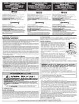
Tramex Concrete Moisture Encounter Meter (Figure 2): Moisture readings
should not exceed 4.5 on the upper scale. (Figure 2 shows an unacceptable
reading of over 4.5.)
NOTE: The following tests are required in commercial applications. Either or
both tests are acceptable.
Calcium Chloride Test (ASTM F 1869): The maximum moisture transfer
must not exceed 3 lbs./1000 ft
2
in 24 hrs. with this test.
RH Levels in Concrete Using In-situ Probes (ASTM F 2170-02) should not
exceed 75%.
“DRY” CONCRETE, AS DEFINED BY THESE TESTS CAN BE WET AT OTHER TIMES OF THE YEAR. THESE TESTS DO
NOT GUARANTEE A DRY SLAB. ALL NEW CONSTRUCTION CONCRETE SLABS SHOULD HAVE A MINIMUM OF 10 MIL
P
OLY FILM MOISTURE BARRIER BETWEEN THE GROUND AND THE CONCRETE.
Wood/Concrete Subfloor Systems
Fastened to concrete:
Concrete must be of high compressive strength, 3000 PSI or better. Install a suitable moisture retardant followed by a
plywood subfloor with a minimum thickness of 3/4
ʺ (19 mm). Allow 1/2ʺ (13 mm) expansion space around all vertical
objects and 1/8
ʺ (3 mm) between all flooring panels. In general, smaller panels [less than 4ʹ x 8ʹ (1.2 m x 2.4 m)]
oriented at 45 degrees (preferred) offer better results. The panel must be properly attached to the subfloor using a
minimum of one fastener per square foot, and more if necessary. Use pneumatic or powder actuated fasteners. Do not
hand nail the subfloor with concrete nails. Install a moisture retardant barrier with joints lapped 6
ʺ (15 cm) and begin
installation of flooring using 1-1/2
ʺ (4 cm) fasteners.
Floating subfloor:
Install a suitable moisture retardant followed by a plywood subfloor with a minimum of 3/8ʺ (9.5mm) [1/2ʺ (13 mm)
preferred]. Allow 1/2
ʺ (13 mm) expansion space around all vertical objects and 1/8ʺ (3 mm) between all flooring panels.
Install a second layer of plywood, the same thickness, at a right angle to the previous panels, offsetting the joints 2
ʹ
(61 cm). Staple together with staples that will not penetrate the first layer of the subfloor. The staples should have a
crown width of 3/8
ʺ (9.5 mm) or more. Install a moisture retardant barrier with joints lapped 6ʺ (15 cm) and begin
installation of flooring using 1-1/2
ʺ (4 cm) fasteners.
Screeds/sleepers:
Solid hardwood flooring 4ʺ (10 cm) and above in width cannot be installed directly to screeds. Screeds should be
installed 9
ʺ (23 cm) apart, in rivers of adhesive, at right angles to the flooring to be installed. Do not begin installation
until all adhesives are properly cured. Install moisture retardant over the screeds prior to installation of the flooring.
IV. INSTALLING THE FLOOR
General Installation Tips
Floor should be installed from several cartons at the same time to ensure good color and shade mixture.
When possible, preselect and set aside boards that blend best with all floor mounted moldings used to ensure a uniform
final appearance. Install these boards adjoining the moldings.
Be attentive to staggering the ends of boards at least 4
ʺ–6ʺ (10–15 cm),
when possible, in adjacent rows (Figure 3). This will help ensure a more
favorable overall appearance of the floor.
Large spans exceeding 20
ʹ (6 m) in hardwood flooring width, in areas of
high humidity, may require the addition of internal or field expansion. This
can be accomplished by using spacers, such as small washers, every
10–20 rows inserted above the tongue. Remove the spacers after several
adjoining rows have been fastened. Do not leave spacers in for more than
two hours.
When installing products of uniform length, begin the rows with starter
boards cut to various lengths. Avoid staggering the rows uniformly to
prevent stair-stepping. Boards cut from the opposite end of the row may be used for the next starter boards.
Always allow a minimum 3/4
ʺ (19 mm) expansion around all vertical obstructions.
Always use a protective foot on the fastening machine to prevent mallet damage and edge bruising.
General Information for “Blind Fastening” Machines
Avoid striking the edge of prefinished products with the fastener’s mallet. Edge crushing can occur, causing unsightly
cracks and splinters. Use a protective foot attachment to prevent edge bruising and finish damage.
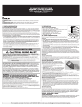
Improper adapter plates and air pressure settings can cause severe damage
to the hardwood flooring and reduce performance (Figure 4). Always use an
in-line regulator to control air pressure to the machine. Set pressure at
70–75 PSI to begin with and adjust until proper fastener setting occurs.
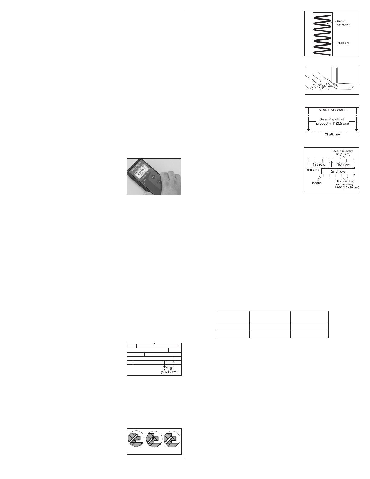
NOTE: SPECIAL INSTRUCTIONS FOR PLANK FLOORING
Seasonal distortion (shrinkage/cupping) in wide width flooring [4
ʺ (10 cm)
and over] may be reduced by gluing the flooring to the subfloor, in addition to
the use of mechanical fasteners. The installer should be reminded that
adhesives used for this purpose will not perform their function when used in
conjunction with a moisture retardant. Glue-assisted applications will not be
satisfactory without direct contact with the subfloor. The glue should be a
premium grade urethane construction adhesive applied in a serpentine
pattern to the back of the hardwood as noted in Figure 5.
S
TEP 1: Doorway and Wall Preparation
Undercut door casings and jambs. Remove any existing base, shoe mold or
doorway thresholds. These items can be replaced after installation. All door
casings and jambs should be undercut to avoid difficult scribe cuts (Figure 6).
Install the moisture retardant (if used) parallel to the flooring. Overlap the
rows 6
ʺ (15 cm). Overlap (top) should be on the same side as the groove
of the flooring so that the hardwood will slide smoothly into place. Staple
t
he moisture retardant material as necessary to prevent excessive
m
ovement.
S
TEP 2: Establish a Starting Point
Installation parallel to the longest wall is recommended for best visual
effects; however, the floor should be installed perpendicular to the flooring
joists unless subfloor has been reinforced to reduce subfloor sagging.
When possible, always begin layout or installation from the straightest wall,
generally an outside wall.
In at least two places at least 18
ʺ (46 cm) from the corner, measure out
e
qual distance from the starting wall (Figure 7) the face width of the starter
b
oard plus 1ʺ (
2.5 cm) (do not include the width of the tongue in this
measurement). Mark these points and snap a chalk line through them. This
measurement allows for the required 3/4
ʺ (19 mm) expansion and the width
of the tongue.
S
TEP 3: Installing First & Second Rows
S
tarting from Wall
Use the longest, straightest boards available for the first two rows. For
r
andom and alternate width products use the widest plank for the first row.
Align tongue of first row on chalk line. The groove should be facing the
starting wall.
Use a pneumatic finish nailer to face-nail the groove side 1/2
ʺ (13 mm) from
the edge at 6
ʺ (15 cm) intervals and 1ʺ3ʺ (2.5–7.6 cm) from each end. Then,
blind nail using a finishing gun held at a 45° angle. Nail down through the
nailing “pocket” on top of the tongue every 6
ʺ –8ʺ (15 –20 cm) (Figure 8).
If using finish nails, pre-drill the nail holes with a 1/32
ʺ (2 mm) bit
approximately 1/2
ʺ (13 mm) from back (groove) edge, 1ʺ–3ʺ (2.5–7.6 cm)
from each end, and at 6
ʺ (15 cm) intervals. Pre-drill at the same intervals at
a 45° angle down through the nailing “pocket” on top of the tongue
(Figure 8). Face-nail the groove side where pre-drilled. When complete,
blind-nail at a 45° angle through the tongue of the first row. Fasten using 6 or 8d finish nails. Countersink nails to
ensure flush engagement of the groove. Avoid bruising the hardwood by using a nail set to countersink the nails.
Continue blind-nailing using this method with the following rows until blind nailer can be used.
STEP 2–3 Alternative: Installing First & Second Rows
Starting from Center of Room
Snap a chalk line down the center of the room.
Install a sacrificial row that extends the entire length of the room on the centerline.
Install three rows of flooring.
Remove the sacrificial row and insert wood glue in the groove followed by a slip tongue (spline) in the exposed groove.
Always glue and nail the slip tongue in place.
Installation can now continue from the center in both directions.
STEP 4: Dry Lay (Racking) the Floor
“Dry” lay (rack) materials to cover approximately two-thirds of the room. Begin dry laying (racking) approximately 6ʺ
(15 cm) from the edge of the previously installed rows. Avoid pulling boards too tightly together on the sides, as they
must move freely when fastening begins.
Do not cut final board until row has been installed. Cutting the board in advance may result in a board that is too short.
Visually inspect flooring, setting aside boards that need to have natural character flaws cut out.
Use these boards for the starting and finishing rows after objectionable characteristics have been removed.
STEP 5: Installing the Floor
Use the blind nailer to fasten a sacrificial board to the floor. Check for surface damage, air pressure setting, tongue
damage, etc., before proceeding. Make all adjustments and corrections before installation begins. Once proper
adjustments have been made, remove and destroy the board.
Begin installation with several rows at a time. Use the fastener schedule (Figure 9) for proper spacing based on board
width. Fasten each board with a minimum of two fasteners 1
ʺ –3ʺ (2.5–7.6 cm) from the ends. To ensure a more
favorable overall appearance end-joints of adjacent rows should be staggered a minimum of 4
ʺ–6ʺ (10–15 cm) when
possible.
The last 1–2 rows will need to be face-nailed where clearance does not permit blind nailing with the stapler or brad
nailer. Pre-drill and face-nail on the tongue side following the nailing pattern used for the first row.
Rip final row to fit and face-nail. If the final row is less than 1
ʺ (2.5 cm) in width, it should first be glued to the previous
UNINSTALLED row and the two joined units should be face-nailed as one.
STEP 6: Complete the Installation
Remove all tape and clean the floor with the recommended hardwood flooring cleaner.
Install or re-install any transition pieces, reducer strips, T-moldings, thresholds, bases and/or quarter round moldings
that may be needed. These products are available pre-finished to blend with your flooring (see below). Nail moldings
into the wall, not the floor.
Inspect the floor, filling all minor gaps with the appropriate blended filler.
If the floor is to be covered, use a breathable material such as cardboard. Do not cover with plastic.
Leave warranty and floor care information with the owner. Advise them of the product name and code number of the
flooring they purchased.
To prevent surface damage, avoid rolling heavy furniture and appliances on the floor. Use plywood, hardboard or
appliance lifts if necessary. Use protective castors/castor cups or felt pads on the legs of furniture to prevent damage
to the flooring.
Figure 7
2
Figure 2
Figure 3
Preferred Alignment
Figure 5
Figure 6
Figure 8
Fastener Schedule
Width of flooring 1-1/2
ʺ
to 3-1/2
ʺ
4
ʺ
(10 cm) and
(4–9 cm) over
Maximum spacing 10
ʺ
–12
ʺ (
25–30 cm) 8
ʺ
–10
ʺ (
20–25 cm)
Preferred spacing 8
ʺ
–10
ʺ (
20–25 cm) 6
ʺ
–8
ʺ (
15–20 cm)
Figure 9
Figure 4
Too Low
Correct
Too High
debe ser un adhesivo de uretano de alta calidad aplicado en forma de serpentín
en el dorso de la madera dura como se ilustra en la Figura 5.
PASO 1: Preparación de la entrada y de la
pared
• Recorte por debajo los marcos de las puertas. Retire cualquier base, moldura
de zócalo o umbrales del vano de la puerta existentes. Estos artículos pueden
colocarse nuevamente después de la instalación del revestimiento. Todos los
marcos y jambas de las puertas deben ser recortados para evitar líneas de
corte difíciles (Figura 6).
• Instale el retardador de humedad (si se usa) paralelo al piso. Traslape las
hileras 6
ʺ (15 cm). El traslape (superior) debe ser en el mismo lado de la
lengüeta del piso de modo que la madera dura pueda deslizarse suavemente
a
su lugar. Engrape el material retardador de humedad como sea necesario a
n de evitar movimiento excesivo.
P
ASO 2: Determinación de un punto de inicio
Se recomienda que la instalación sea paralela a la pared más larga para lograr
mejores efectos visuales; sin embargo, el piso debe instalarse perpendicular a
las viguetas, a menos que el subsuelo haya sido reforzado para reducir la
flexión del mismo.
Cuando sea posible, siempre comience la disposición o instalación desde la
pared más recta, generalmente de un muro exterior.
Por lo menos en dos lugares, a menos de 18
ʺ (46 cm) desde la esquina, mida
una distancia igual desde la pared inicial (Figura 7) el ancho de la tabla inicial
más 1
ʺ (2.5 cm) (no incluya la anchura de la lengua en esta medida). Marque
estos puntos y pase un cordel entizado sobre ellos. Esta medida ofrece la
expansión requerida de 3/4
ʺ (19 mm) y el ancho de la lengüeta.
PASO 3: Instalación de la primera y de la
segunda hilera Comenzando de la pared
Use los tablones más largos y rectos disponibles para las dos primeras
hileras. Para productos con anchos aleatorios y alternados, use el tablóns
ancho para la primera hilera. Alinee la lengüeta de la primera hilera con el
cordel entizado. La ranura debe quedar dirigida hacia la pared inicial.
Si usa un martillo clavador neumático de acabado para clavar
perpendicularmente el lado de la ranura a 1/2
ʺ (13 mm) desde el borde a
intervalos de 6
ʺ (15 cm) y 1ʺ–3ʺ (2.5–7.6 cm) de cada extremo, entonces
realice el clavado invisible usando la pistola de acabado colocándola en un
ángulo de 45º, clave a través de la “cavidad” situada sobre la lengüeta cada
6
ʺ–8ʺ (15–20 cm) (Figura 8).
Si usa clavos de acabado, taladre con anterioridad los agujeros de los clavos
con una broca de 1/32
ʺ (2 mm) a aproximadamente 1/2ʺ (13 mm) desde el
borde trasero (ranura), 1
ʺ–3ʺ (2.5–7.6 cm) de cada extremo y a intervalos de
6
ʺ (15 cm). Taladre con anterioridad en los mismos intervalos y en un ángulo
de 45º a través de la “cavidad” situada sobre la lengüeta (Figura 8). Clave
perpendicularmente el lado de la ranura que había sido pretaladrado. Cuando
termine, realice el clavado invisible en un ángulo de 45º a través de la lengüeta
de la primera hilera. Asegure utilizando clavos de acabado 6 u 8d. Avellane
los clavos para asegurar el enganche al ras de la ranura. Evite magullar la madera dura cuando utilice un embutidor
de clavos para avellanar los clavos.
Continúe el enclavado invisible usando este método en las hileras siguientes hasta que pueda utilizar una máquina de
clavado invisible.
PASO 2–3 Alternativa: Instalación de la primera y de la segunda
hilera Comenzando desde el centro de la habitación
Trace una línea con el cordel entizado en el centro de la habitación.
Instale una hilera de sacrificio que se extienda a todo el largo de la habitación sobre la línea central.
Instale tres hileras del piso.
Retire la hilera de sacrificio e inserte cola para madera en la ranura seguida de una lengüeta falsa en la ranura expuesta.
Siempre debe encolar y clavar la lengüeta falsa en su lugar.
La instalación puede continuar ahora desde el centro en ambas direcciones.
PASO 4: Instalación en seco del piso
Coloque los materiales “en seco” para cubrir aproximadamente 2/3 del cuarto. Comience colocando el material en seco
a aproximadamente a 6
ʺ (15 cm) desde el borde de las hileras instaladas anteriormente. Evite que las tablas queden
demasiado apretadas en los lados pues deben moverse libremente cuando comience la fijación.
No corte la tabla final hasta que la hilera no haya sido instalada. Si se corta con anterioridad puede que la tabla resulte
demasiado corta.
Inspeccione el piso visualmente, dejando a un lado las tablas con defectos naturales que necesitan recortarse.
Use estas tablas para la hilera inicial y la hilera final después de que se hayan eliminado los defectos objetables.
P
ASO 5: Instalación del piso
Use la clavadora invisible para instalar una tabla de sacrificio en el piso. Verifique si hay daño superficial, el ajuste de
la presión de aire, daño a la lengüeta, etc. antes de proceder. Haga todos los ajustes y correcciones antes de comenzar
la instalación. Una vez que se hayan hecho todos los ajustes adecuados, retire y descarte la tabla de sacrificio.
Comience la instalación con varias hileras de una vez. Use la distribución de sujetadores (Figura 9) para espaciamiento
apropiado en base al ancho de la tabla. Fije cada tabla con un mínimo de dos sujetadores a 1
ʺ–3ʺ (2.5–7.6 cm) desde
los extremos. A fin de asegurar un aspecto general más favorable, las juntas de los extremos de las hileras adyacentes
deben alternarse por lo menos de 4
ʺ–6ʺ (10–15 cm) cuando sea posible.
En las últimas (1–2) hileras use clavado perpendicular cuando el espacio no permita clavadura invisible con la
e
ngrapadora o con la clavadora de clavos de cabeza pequeña. Pretaladre y use clavado perpendicular en el lado de la
lengüeta siguiendo la configuración de clavado que se usó para la primera hilera.
Corte al hilo la última hilera para que calce y clave con clavos insertados en forma perpendicular. Si el ancho de la
última hilera es inferior a 1
ʺ (2.5 cm), primero se debe encolar a la hilera anterior aún NO INSTALADA y las dos hileras
juntas se deben asegurar con clavado perpendicular como si fueran una sola hilera.
P
ASO 6: Termine la instalación
Saque toda la cinta y limpie el piso con el limpiador para pisos de madera dura recomendado.
Instale o vuelva a instalar todas las molduras decalo, tira de reducción, moldura en T, umbrales y/o cuartos de caña.
Estos productos ya vienen terminados para combinar con sus pisos (ver a continuación). Clave las molduras en la
pared, no en el piso.
Inspeccione el piso, y rellene todas las brechas menores con el relleno que combine.
Si se tiene planeado cubrir el piso, use un material que respire como el cartón. No lo cubra con plástico.
Deje la garantía y la información sobre el cuidado del piso con el propietario. Indíquele el nombre del producto y el
número de código del piso que adquirió.
Para no dañar la superficie, no haga rodar muebles o artefactos pesados sobre el piso. De ser necesario, use tablas
de madera contrachapada, de fibra dura o soportes para artefactos. Use bases protectoras o cojinetes de fieltro en las
ruedas y las patas de los muebles para no dañar el piso.
V. MOLDURAS DE TRANSICIÓN Y PARA LA PARED
Tira de reducción: Una moldura en forma de lágrima que se usa alrededor de las chimeneas, las entradas, para dividir
habitaciones, o como transición entre pisos de madera y revestimientos de pisos contiguos más delgados. Sujételas
c
on adhesivo, clavitos o con una cinta adhesiva doble.
Umbral: Una moldura cortada por debajo que se usa contra los rieles de puertas corredizas, chimeneas, alfombras,
losetas de cerámica o umbrales existentes, para dejar un espacio de expansión y proporcionar una transición suave
en lugares con alturas diferentes. Sujételos a la base con adhesivo y/o con clavos a través del talón. Perfore los orificios
de los clavos de antemano para no rajarlo.
Mamperlán: Una moldura cortada por debajo que se usa como reborde en rellano de escaleras, perímetros de pisos
elevados o en escalones. Sujételos firmemente con clavos o con tornillos. Perfore los orificios de los clavos de
antemano para no rajarlo.
Cuarto de caña: Una moldura que se usa para cubrir espacios de expansión cerca de zócalos, muebles encerrados y
escalones. Perfore los orificios de antemano y clávelos en la superficie vertical, no en el piso.
Combinación de base y contera: Una moldura usada cuando se desea una base. Usada para cubrir espacio de
expansión entre el piso y la pared. Pretaladre y clave en la pared, no en el piso.
Moldura en T: Una moldura que se usa como sección de transición desde un piso al otro de igual altura, o para obtener
espacios de expansión. Sujételas en el talón, en el centro de la moldura. Es posible que necesiten más soporte en el
talón, según el espesor de los muebles que se cubran.
INSTALADORES – COMUNIQUE AL CLIENTE LAS SIGUIENTES
RECOMENDACIONES
Estaciones: Temporada con calefacción y sin calefacción
Considerando que las dimensiones del piso de madera se verán ligeramente afectadas por los diferentes niveles de
humedad dentro del edificio, se debe tener cuidado de controlar los niveles de humedad dentro de un límite del 35 al
55%. Para proteger su inversión y asegurar que sus pisos le proporcionen una satisfacción duradera, recomendamos lo
siguiente:
Temporada con calefacción (ambiente seco) Se recomienda usar un humidificador para evitar el encogimiento
excesivo de los pisos de madera debido a los niveles bajos de humedad. Las estufas de madera y el calor eléctrico
tienden a crear condiciones muy secas.
Temporada sin calefacción (ambiente húmedo, mojado) Se pueden mantener los niveles apropiados de humedad
usando un acondicionador de aire, un deshumidificador o encendiendo el sistema de calefaccn perdicamente durante
los meses de verano. Evite la exposición excesiva al agua durante los períodos de tiempo inclemente. No obstruya de
ninguna manera la junta de expansn alrededor del perímetro del piso.
NOTA: La inspección final por el usuario final debe ocurrir de una posición parada.
REPARACIÓN DEL PISO
Los daños menores pueden repararse con un kit de retoque o relleno de Armstrong
®
, Bruce
®
o Robbins
®
. Los daños
más grandes requerirán el reemplazo de las tablas, lo cual debe realizar un instalador profesional de pisos.
7
Distribucion de los Sujetadores
Ancho del piso 1-1/2
ʺ
a 3-1/2
ʺ
4
ʺ
(10 cm) y más
(4–9 cm)
Espaciamiento máximo 10
ʺ
–12
ʺ (
25–30 cm) 8
ʺ
–10
ʺ (
20 –25 cm)
Espaciamiento preferido 8
ʺ
–10
ʺ (
20–25 cm) 6
ʺ
–8
ʺ (
15–20 cm)
Figura 9
T
ira de reducción Umbral Mampirlán Cuarto de caña Combinación de
base y contera
Moldura en T
Figura 6
F
igura 7
F
igura 5
Figura 8
Armstrong and the Armstrong logo are trademarks of AWI
Licensing LLC. All other trademarks are owned by Armstrong
Flooring, Inc. or its subsidiaries.
Armstrong et le logo Armstrong sont des marques de commerce
appartenant à AWI Licensing LLC. Toutes les autres marques de
commerce appartiennent à Armstrong Flooring, Inc. ou à ses
sociétés affiliées.
Armstrong y el logotipo de Armstrong logo son marcas
comerciales de AWI Licensing LLC. Todas las otras marcas
comerciales son propiedad de Armstrong Flooring, Inc. o sus
subsidiarias.
© 2016 Armstrong Flooring, Inc. Armstrong Hardwood Flooring Company 2500 Columbia Ave., Lancaster, PA 17603
Printed in the United States of America / Imprimé aux États-Unis d’Amérique / Imprimido en los Estados Unidos de América
LA-295726-816
1 / 1

Robbins AHS1100 Installation guide

Type
Installation guide

Ask a question and I''ll find the answer in the document

Finding information in a document is now easier with AI

Ask the document