Page is loading ...

MX240 3D Universal Edge Router
Quick Start
January 2015
Part Number: 530-040793
Revision 01
This document describes how to install the Juniper Networks
®
MX240 3D Universal Edge
Router.
Contents
MX240 Quick Start Description . . . . . . . . . . . . . . . . . . . . . . . . . . . . . . . . . . . . . . . . . 3
Step 1: Prepare the Site for MX240 Installation . . . . . . . . . . . . . . . . . . . . . . . . . . . . 4
MX240 Rack-Mounting Requirements . . . . . . . . . . . . . . . . . . . . . . . . . . . . . . . 4
Tools Required to Unpack and Prepare the MX240 Router for
Installation . . . . . . . . . . . . . . . . . . . . . . . . . . . . . . . . . . . . . . . . . . . . . . . . . . 5
Step 2: Install the Mounting Hardware in a Four-Post Rack or Cabinet or an
Open-Frame Rack . . . . . . . . . . . . . . . . . . . . . . . . . . . . . . . . . . . . . . . . . . . . . . . . 6
Step 3: Install the Router . . . . . . . . . . . . . . . . . . . . . . . . . . . . . . . . . . . . . . . . . . . . . . 9
Remove Components . . . . . . . . . . . . . . . . . . . . . . . . . . . . . . . . . . . . . . . . . . . . . 9
Install the Router Using a Lift . . . . . . . . . . . . . . . . . . . . . . . . . . . . . . . . . . . . . . 10
Install the Router Without a Mechanical Lift . . . . . . . . . . . . . . . . . . . . . . . . . . 12
Reinstall Components . . . . . . . . . . . . . . . . . . . . . . . . . . . . . . . . . . . . . . . . . . . . 13
Step 4: Connect the Grounding Cable . . . . . . . . . . . . . . . . . . . . . . . . . . . . . . . . . . . 14
Step 5: Connect External Devices and DPC or PIC Cables . . . . . . . . . . . . . . . . . . . 15
Connect to a Network for Out-of-Band Management . . . . . . . . . . . . . . . . . . . 15
Connect a Management Console . . . . . . . . . . . . . . . . . . . . . . . . . . . . . . . . . . . 15
Connect the Line Card Cables . . . . . . . . . . . . . . . . . . . . . . . . . . . . . . . . . . . . . . 15
Step 6: Connect Power Cables . . . . . . . . . . . . . . . . . . . . . . . . . . . . . . . . . . . . . . . . . 17
Connect Power to an AC Router with Normal-Capacity Power Supplies . . . . 17
Connect Power to an AC Router with High-Capacity Power Supplies . . . . . . 18
Connect Power to a DC Router with Normal-Capacity Power Supplies . . . . . 19
Connect Power to a DC Router with High-Capacity Power Supplies . . . . . . . . 21
Step 7: Perform Initial Software Configuration . . . . . . . . . . . . . . . . . . . . . . . . . . . . 23
Enter Configuration Mode . . . . . . . . . . . . . . . . . . . . . . . . . . . . . . . . . . . . . . . . . 23
Configure User Accounts and Passwords . . . . . . . . . . . . . . . . . . . . . . . . . . . . 23
Configure System Attributes . . . . . . . . . . . . . . . . . . . . . . . . . . . . . . . . . . . . . . 24
Commit the Configuration . . . . . . . . . . . . . . . . . . . . . . . . . . . . . . . . . . . . . . . . 24
Safety Warnings . . . . . . . . . . . . . . . . . . . . . . . . . . . . . . . . . . . . . . . . . . . . . . . . . . . . 26
1Copyright © 2015, Juniper Networks, Inc.

Compliance Statements for NEBS . . . . . . . . . . . . . . . . . . . . . . . . . . . . . . . . . . . . . 27
Compliance Statements for EMC Requirements . . . . . . . . . . . . . . . . . . . . . . . . . . 28
Canada . . . . . . . . . . . . . . . . . . . . . . . . . . . . . . . . . . . . . . . . . . . . . . . . . . . . . . . 28
European Community . . . . . . . . . . . . . . . . . . . . . . . . . . . . . . . . . . . . . . . . . . . . 28
Israel . . . . . . . . . . . . . . . . . . . . . . . . . . . . . . . . . . . . . . . . . . . . . . . . . . . . . . . . . 28
Japan . . . . . . . . . . . . . . . . . . . . . . . . . . . . . . . . . . . . . . . . . . . . . . . . . . . . . . . . . 28
United States . . . . . . . . . . . . . . . . . . . . . . . . . . . . . . . . . . . . . . . . . . . . . . . . . . 29
Junos Documentation and Release Notes . . . . . . . . . . . . . . . . . . . . . . . . . . . . . . . 30
Requesting Technical Support . . . . . . . . . . . . . . . . . . . . . . . . . . . . . . . . . . . . . . . . 30
Self-Help Online Tools and Resources . . . . . . . . . . . . . . . . . . . . . . . . . . . . . . 30
Opening a Case with JTAC . . . . . . . . . . . . . . . . . . . . . . . . . . . . . . . . . . . . . . . . . 31
Revision History . . . . . . . . . . . . . . . . . . . . . . . . . . . . . . . . . . . . . . . . . . . . . . . . . . . . . 31
Copyright © 2015, Juniper Networks, Inc.2
MX240 3D Universal Edge Router Quick Start

MX240 Quick Start Description
This Quick Start contains information you need to install and configure the router quickly.
For complete installation instructions, see the MX240 3D Universal Edge Router Hardware
Guide at http://www.juniper.net/techpubs/.
WARNING: This Quick Start contains a summary of safety warnings in “Safety
Warnings” on page 26. For a complete list of warnings for this router, including
translations, see the MX240 3D Universal Edge Router Hardware Guide at
http://www.juniper.net/techpubs/.
The router is shipped in a cardboard box strapped securely to a wooden pallet. Plastic
straps secure the top and bottom in place. The router chassis is bolted to this pallet.
Quick Start installation instructions and a cardboard accessory box are also included in
the shipping container.
3Copyright © 2015, Juniper Networks, Inc.
MX240 Quick Start Description

Step 1: Prepare the Site for MX240 Installation
•
MX240 Rack-Mounting Requirements on page 4
•
Tools Required to Unpack and Prepare the MX240 Router for Installation on page 5
MX240 Rack-Mounting Requirements
•
You can install the router in a four-post rack or cabinet or an open-frame rack.
•
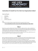
The rack rails must be spaced widely enough to accommodate the router chassis's
external dimensions: 8.71 in. (22.1 cm) high, 24.5 in. (62.2 cm) deep, and
17.45 in. (44.3 cm) wide. The mounting brackets extend the width to 19 in. (48.3 cm).
•
The rack must be strong enough to support the weight of the fully configured router,
up to 128 lb (58.1 kg).
•
For the cooling system to function properly, the airflow around the chassis must be
unrestricted. Allow at least 6 in. (15.2 cm) of clearance between side-cooled routers.
Allow 2.8 in. (7 cm) between the side of the chassis and any non-heat-producing
surface such as a wall.
•
For service personnel to remove and install hardware components, there must be
adequate space at the front and back of the router. Allow at least 30 in. (76.2 cm) in
front of the router and 24 in. (61 cm) behind the router.
•
The rack or cabinet must have an adequate supply of cooling air.
•
Ensure that the cabinet allows the chassis hot exhaust air to exit from the cabinet
without recirculating into the router.
•
The router must be installed into a rack that is secured to the building structure.
•
Mount the router at the bottom of the rack if it is the only unit in the rack.
•
When mounting the router in a partially filled rack, load the rack from the bottom to
the top with the heaviest component at the bottom of the rack.
Copyright © 2015, Juniper Networks, Inc.4
MX240 3D Universal Edge Router Quick Start

Figure 1: MX240 Rack Clearance and Router Dimensions
Tools Required to Unpack and Prepare the MX240 Router for Installation
To unpack the router and prepare for installation, you need the following tools:
•
A mechanical lift—recommended
•
Phillips (+) screwdrivers, numbers 1 and 2
•
2.5-mm flat-blade (–) screwdriver
•
7/16-in. (11 mm) torque-controlled driver or socket wrench
•
1/2-in. or 13-mm open-end or socket wrench to remove bracket bolts from the shipping
pallet
•
Electrostatic discharge wrist strap
•
Antistatic mat
Proceed to “Step 2: Install the Mounting Hardware in a Four-Post Rack or Cabinet or an
Open-Frame Rack” on page 6.
5Copyright © 2015, Juniper Networks, Inc.
Tools Required to Unpack and Prepare the MX240 Router for Installation

Step 2: Install the Mounting Hardware in a Four-Post Rack or Cabinet or an Open-Frame
Rack
To install the mounting shelf on the front rails of a four-post rack or cabinet, or the rails
of an open-frame rack:
1. If needed, install cage nuts in the holes specified in Table 1 on page 6.
2. On the back of each rack rail, partially insert a mounting screw into the lowest hole
specified in Table 1 on page 6.
3. Install the mounting shelf on the back of the rack rails. Rest the bottom slot of each
flange on a mounting screw.
4. Partially insert screws into the open holes in each flange of the mounting shelf (see
Figure 2 on page 7 or Figure 3 on page 8).
5. Tighten all the screws completely.
Table 1: MX240 Mounting Hole Locations
Mounting ShelfDistance Above U DivisionHole
X1.14 U2.00 in. (5.1 cm)4
X0.86 U1.51 in. (3.8 cm)3
X0.50 U0.88 in. (2.2 cm)2
X0.14 U0.25 in. (0.6 cm)1
Copyright © 2015, Juniper Networks, Inc.6
MX240 3D Universal Edge Router Quick Start

Figure 2: Mounting Hardware for a Four-Post Rack or Cabinet
g004258
Four-post open rack
Small mounting shelf
7Copyright © 2015, Juniper Networks, Inc.
Step 2: Install the Mounting Hardware in a Four-Post Rack or Cabinet or an Open-Frame Rack


Step 3: Install the Router
Because of the router's size and weight, you must remove all components before installing
the router. We also recommend that you install the router using a mechanical lift.
•
Remove Components on page 9
•
Install the Router Using a Lift on page 10
•
Install the Router Without a Mechanical Lift on page 12
•
Reinstall Components on page 13
Remove Components
Figure 4: Components to Remove from the Front of the MX240 Router
Figure 5: Components to Remove from the Rear of the MX240 Router
Before lifting the router, you must remove the following components:
•
Power supplies
•
Switch Control Boards (SCBs)
•
Routing Engines
•
Air filter
•
Fan tray
•
Line cards:
9Copyright © 2015, Juniper Networks, Inc.
Step 3: Install the Router

•
Dense Port Concentrators (DPCs)
•
Flexible PIC Concentrators (FPCs)
•
Physical Interface Cards (PICs)
•
Modular Port Concentrators (MPCs)
•
Modular Interface Cards (MICs)
To remove the components from the router:
1. Slide each component out of the chassis evenly so that it does not become stuck or
damaged.
2. Label each component as you remove it so you can reinstall it in the correct location.
3. Immediately store each removed component in an electrostatic bag.
4. Do not stack removed components. Lay each one on a flat surface.
NOTE: For complete instructions on removing router components, see
“Installing the MX240 Chassis in the Rack Manually” in the MX240 3D Universal
Edge Router Hardware Guide.
Install the Router Using a Lift
To install the router using a lift:
1. Ensure that the rack is in its permanent location and is secured to the building. Ensure
that the installation site allows adequate clearance for both airflow and maintenance.
For details, see the MX240 3D Universal Edge Router Hardware Guide.
2. Load the router onto the lift, making sure it rests securely on the lift platform (see
Figure 6 on page 11).
Copyright © 2015, Juniper Networks, Inc.10
MX240 3D Universal Edge Router Quick Start

Figure 6: Load the MX240 Router onto the Lift
3. Using the lift, position the router in front of the rack or cabinet, centering it in front of
the mounting shelf.
4. Lift the chassis approximately 0.75 in. above the surface of the mounting shelf and
position it as close as possible to the shelf.
5. Carefully slide the router onto the mounting shelf so that the bottom of the chassis
and the mounting shelf overlap by approximately 2 inches.
6. Slide the router onto the mounting shelf until the mounting brackets contact the rack
rails. The shelf ensures that the holes in the mounting brackets align with the holes
in the rack rails.
7. Move the lift away from the rack.
8. Install a mounting screw into each of the open mounting holes aligned with the rack,
starting from the bottom.
9. Visually inspect the alignment of the router. If the router is installed properly in the
rack, all the mounting screws on one side of the rack should be aligned with the
mounting screws on the opposite side, and the router should be level.
11Copyright © 2015, Juniper Networks, Inc.
Install the Router Using a Lift

Install the Router Without a Mechanical Lift
At least two people are required to lift an empty chassis, which weighs approximately
65.5 lb (29.7 kg), and mount it in a rack. Three people are required to lift a fully configured
router, which can weigh up to 128 lb (58.1 kg).
To install the router without a mechanical lift:
1. Ensure that the rack is in its permanent location and is secured to the building.
2. Position the router in front of the rack or cabinet, centering it in front of the mounting
shelf. Use a pallet jack if one is available.
3. With one person or two people on each side, hold onto the bottom of the chassis and
carefully lift it onto the mounting shelf.
4. Slide the router onto the mounting shelf until the mounting brackets contact the rack
rails. The shelf ensures that the holes in the mounting brackets align with the holes
in the rack rails.
5. Install a mounting screw into each of the open mounting holes aligned with the rack,
starting from the bottom.
6. Visually inspect the alignment of the router. If the router is installed properly in the
rack, all the mounting screws on one side of the rack should be aligned with the
mounting screws on the opposite side and the router should be level.
Figure 7: Lift the MX240 Router into the Rack
Copyright © 2015, Juniper Networks, Inc.12
MX240 3D Universal Edge Router Quick Start

Reinstall Components
To reinstall the components in the router:
1. Slide each component into the chassis evenly so that it does not become stuck or
damaged.
2. Tighten the captive screws for each component.
NOTE: Make sure that all empty slots are covered with a blank panel before
operating the router.
Proceed to “Step 4: Connect the Grounding Cable” on page 14.
13Copyright © 2015, Juniper Networks, Inc.
Reinstall Components

Step 4: Connect the Grounding Cable
1. Attach an electrostatic discharge (ESD) grounding strap to your bare wrist, and connect
the strap to an approved site ESD grounding point. See the instructions for your site.
2. Connect the grounding cable to a proper earth ground.
3. Verify that a licensed electrician has attached the cable lug provided with the router
to the grounding cable.
4. Make sure that grounding surfaces are clean and brought to a bright finish before
grounding connections are made.
5. Attach an electrostatic discharge (ESD) grounding strap to your bare wrist, and connect
the strap to one of the ESD points on the chassis. For more information about ESD,
see the MX240 Ethernet Services Router Hardware Guide
6. Place the grounding cable lug over the grounding points.point on the top rear of the
chassis. The grounding point is sized for UNC 1/4-20 bolts.
7. Secure the grounding cable lug to the grounding points, first with the washers, then
with the screws.
8. Verify that the grounding cabling is correct, that the grounding cable does not touch
or block access to router components, and that it does not drape where people could
trip on it.
Proceed to “Step 5: Connect External Devices and DPC or PIC Cables” on page 15.
Copyright © 2015, Juniper Networks, Inc.14
MX240 3D Universal Edge Router Quick Start

Step 5: Connect External Devices and DPC or PIC Cables
Figure 8: Routing Engine Management Ports
•
Connect to a Network for Out-of-Band Management on page 15
•
Connect a Management Console on page 15
•
Connect the Line Card Cables on page 15
Connect to a Network for Out-of-Band Management
1. Turn off the power to the management device.
2. Plug one end of the RJ-45 Ethernet cable into the appropriate ETHERNET port on the
Routing Engine.
3. Plug the other end of the cable into the network device.
Connect a Management Console
1. Turn off the power to the management device.
2. Plug the RJ-45 end of the serial cable into the appropriate CONSOLE or AUX port on
the Routing Engine.
3. Plug the female DB-9 end of the serial cable into the device's serial port.
Connect the Line Card Cables
1. Have ready a length of the type of cable used by the line card. For cable specifications,
see the MX Series Interface Module Reference.
2. If the cable connector port is covered by a rubber safety plug, remove the plug.
WARNING: Do not look directly into a fiber-optic transceiver or into the
ends of fiber-optic cables. Fiber-optic transceivers and fiber-optic cable
connected to a transceiver emit laser light that can damage your eyes.
CAUTION: Do not leave a fiber-optic transceiver uncovered except when
inserting or removing cable. The safety cap keeps the port clean and
prevents accidental exposure to laser light.
15Copyright © 2015, Juniper Networks, Inc.
Step 5: Connect External Devices and DPC or PIC Cables

CAUTION: Avoid bending fiber-optic cable beyond its minimum bend
radius. An arc smaller than a few inches in diameter can damage the cable
and cause problems that are difficult to diagnose.
CAUTION: Do not let fiber-optic cable hang free from the connector. Do
not allow fastened loops of cable to dangle, which stresses the cable at
the fastening point.
Figure 9: Connect DPC Cables
Proceed to “Step 6: Connect Power Cables” on page 17.
Copyright © 2015, Juniper Networks, Inc.16
MX240 3D Universal Edge Router Quick Start

Step 6: Connect Power Cables
Depending on your configuration, your router uses either normal-capacity or high-capacity
AC or DC power supplies. Perform the appropriate procedures for each power supply in
your router.
WARNING: You must ground the router before connecting either the AC
power cord or the DC power cables.
•
Connect Power to an AC Router with Normal-Capacity Power Supplies on page 17
•
Connect Power to an AC Router with High-Capacity Power Supplies on page 18
•
Connect Power to a DC Router with Normal-Capacity Power Supplies on page 19
•
Connect Power to a DC Router with High-Capacity Power Supplies on page 21
Connect Power to an AC Router with Normal-Capacity Power Supplies
WARNING: The router must be properly grounded before you connect the
AC power cords.
1. Attach an electrostatic discharge (ESD) grounding strap to your bare wrist, and connect
the strap to one of the ESD points on the chassis. For more information about ESD,
see the MX240 3D Universal Edge Router Hardware Guide.
2. Locate the power cords, which should have a plug appropriate for your geographical
location. See the MX240 3D Universal Edge Router Hardware Guide.
3. Move the circuit breaker on the power supply faceplate to the off position (O).
4. Insert the appliance coupler end of the power cord into the appliance inlet on the
power supply.
5. Insert the power cord plug into an external AC power source receptacle.
NOTE: Each power supply must be connected to a dedicated AC power
feed and a dedicated customer site circuit breaker. We recommend that
you use a minimum, or as permitted by local code.
6. Dress the power cord appropriately. Verify that the power cord does not block the air
exhaust and access to router components, or drape where people could trip on it.
7. Repeat Step 2 through Step 6 for the remaining power supplies.
8. Switch the AC switch on each power supply to the on position (—) and observe the
status LEDs on each power supply faceplate. If an AC power supply is correctly installed
and functioning normally, the AC OK and DC OK LEDs light steadily, and the PS FAIL
LED is not lit.
17Copyright © 2015, Juniper Networks, Inc.
Step 6: Connect Power Cables

If any of the status LEDs indicates that the power supply is not functioning normally,
repeat the installation and cabling procedures.
Connect Power to an AC Router with High-Capacity Power Supplies
To install a high-capacity AC power supply:
1. Move the AC input switch next to the appliance inlet on the power supply to the off (O)
position.
2. Using both hands, slide the power supply straight into the chassis until the power
supply is fully seated in the chassis slot as shown in Figure 10 on page 18. The power
supply faceplate should be flush with any adjacent power supply faceplate or blank
installed in the power supply slot.
3. Tighten both captive screws at the bottom of the power supply.
4. Attach the power cord to the power supply.
5. Attach the power cord to the AC power source, and switch on the dedicated customer
site circuit breaker. Follow the instructions for your site.
6. Move the AC input switch next to the appliance inlet on the power supply to the on
(|) position and observe the status LEDs on the power supply faceplate. If the power
supply is correctly installed and functioning normally, the AC OK and DC OK LEDs light
steadily and the PS FAIL LED is not lit.
Figure 10: Installing an AC Power Supply
Copyright © 2015, Juniper Networks, Inc.18
MX240 3D Universal Edge Router Quick Start

Connect Power to a DC Router with Normal-Capacity Power Supplies
WARNING: The router must be properly grounded before you connect the
DC power cables.
Table 2: MX240 DC Power System Input Voltage
SpecificationItem
Operating range: –40.5 to –72 VDCDC input voltage
CAUTION: You must ensure that power connections maintain the proper
polarity. The power source cables might be labeled (+) and (–) to indicate
their polarity. There is no standard color coding for DC power cables. The
color coding used by the external DC power source at your site determines
the color coding for the leads on the power cables that attach to the terminal
studs on each power supply.
1. Ensure that the voltage across the DC power source cable leads is 0 V and that there
is no chance that the cable leads might become active during installation.
2. Attach an electrostatic discharge (ESD) grounding strap to your bare wrist, and connect
the strap to one of the ESD points on the chassis. For more information about ESD,
see the MX240 3D Universal Edge Router Hardware Guide.
3. Switch the circuit breaker on the power supply faceplate to the OFF position (O).
4. Remove the clear plastic cover protecting the terminal studs on the faceplate.
5. Secure the power cable lugs to the terminal studs on the power supply, first with the
split washer, then with the nut. Apply between 23 lb-in. (2.6 Nm) and 25 lb-in. (2.8 Nm)
of torque. Do not overtighten the nut. (Use a 7/16-in. [11 mm] torque-controlled driver
or socket wrench.)
a. Attach the positive (+) DC source power cable lug to the RTN (return) terminal.
b. Attach the negative (–) DC source power cable lug to the –48V (input) terminal.
19Copyright © 2015, Juniper Networks, Inc.
Connect Power to a DC Router with Normal-Capacity Power Supplies

Figure 11: Connect Power Cables
CAUTION: Ensure that each power cable lug seats flush against the surface
of the terminal block as you are tightening the nuts. Ensure that each nut
is properly threaded onto the terminal stud. The nut should be able to spin
freely with your fingers when it is first placed onto the terminal stud.
Applying installation torque to the nut when improperly threaded may
result in damage to the terminal stud.
CAUTION: The maximum torque rating of the terminal studs on the DC
power supply is 36 lb-in. (4.0 Nm). The terminal studs may be damaged
if excessive torque is applied. Use only a torque-controlled driver or socket
wrench to tighten nuts on the DC power supply terminal studs.
6. Replace the clear plastic cover over the terminal studs on the faceplate.
7. Repeat Step 3 through Step 6 for the remaining power supplies.
8. Attach an electrostatic discharge (ESD) grounding strap to your bare wrist, and connect
the strap to an approved site ESD grounding point. See the instructions for your site.
9. Connect each DC power cable to the appropriate external DC power source.
NOTE: For information about connecting to external DC power sources,
see the instructions for your site.
Copyright © 2015, Juniper Networks, Inc.20
MX240 3D Universal Edge Router Quick Start
/