Page is loading ...

KOSMOS SERIES
CODE: 30727311 EDITION: 19-01-2011
MAIN MANUAL ADENDUM
MODEL BETA-MP
MODBUS-RTU PROTOCOL COMPATIBLE
KOSMOS SERIES
CODE: 30727311 EDITION: 19-01-2011
MAIN MANUAL ADENDUM
MODEL BETA-MP
MODBUS-RTU PROTOCOL COMPATIBLE

2
2

3
3
INDEX
MEMORY LAYOUT ................................................................................................................................ 4
SENSOR SELECTION ............................................................................................................................. 5
SAVING/ CHANGING A SENSOR CONFIGURATION .................................................................................. 6
LOCKOUT ............................................................................................................................................ 7
PROGRAMMING THE MEMORY VIA SERIAL CHANNEL ............................................................................. 8
TABLE OF MEMORY ADDRESSES ......................................................................................................... 14

4
4
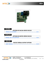
MEMORY LAYOUT
The physical memory is divided into 8 blocks of 566
bytes.
Each block includes the PROGRAMMING DATA
necessary to configure the meter for a particular
sensor, and the DYNAMIC VARIABLES such as PEAK,
VALLEY, TARE, TOTAL and BATCH that are obtained
during the operation of the meter in a specific
configuration.
All this data is repeated 8 times into the memory, and
saved within each sensor block.
There is also a special block of memory common to all
configurations where it is saved the address of the
block being used.
BLOCK 0 - pointer to sensor
SENSOR BLOCK 1
address 0
address 1
......
......
address 544
......
0x0000
0x0020
0x0260
0x0FE0
Physical Software
Memory Addresses
Address
SENSOR BLOCK 2
address 0
address 1
......
......
address 544
......
...
...
SENSOR BLOCK 8
address 0
address 1
......
......
address 544
......
......
...
...

5
5
SENSOR SELECTION
From the normal operating mode, press
"ENTER" to get access to the "-Pro-"
level.
Press "MAX/MIN" to see the sensor
configuration being used. It is
represented by the number of the sensor
block in flash. Set the desired block
number by means of the "LIMIT" key.
Press "ENTER" to display the message
"USE" and press "ENTER" to store the
new sensor selection and return to the
normal operation. The meter is now
working with the data of the selected
sensor.
The dynamic variables such as PEAK,
VALLEY, TARE, TOTAL and BATCH are
not transferred from one to other
configuration when the sensor block is
changed.
They are automatically saved ON
POWER-DOWN within the data of the
block BEING IN USE, while in a specific
sensor block configuration. When you
change to another sensor configuration
without saving them, they are lost.
88888
8
-Pr
o-
SE
n
Sor
1
'ENTER' 'MAX/MIN'
'LIMIT'
-change
current sensor-
USE
Sto
r
E
88888
8
Co
n
F
'ENTER'
'ENTER'
'MAX/MIN' 'MAX/MIN'

6
9
6
SAVING/ CHANGING A SENSOR CONFIGURATION
88888
8
-Pr
o-
SE
n
Sor
1
'ENTER' 'MAX/MIN'
'LIMIT'
-change
current sensor-
USE
Co
n
F
'ENTER' 'MAX/MIN' 'MAX/MIN'
'ENTER'
C
nFIn
P
1
0
'MAX/MIN'
-Pr
o-
'MAX/MIN'
Sto
r
E
To change the programming data of a specific sensor block, go to the "SEnSor" menu and select the number of
the block to be programmed.
Press "ENTER" and "MAX/MIN" to display the message "ConF" and press
"ENTER" again to get access to the programming modules.
At the end of each module, the display shows the message "-
Pro-", from where you may either press "ENTER" to save the
changes and go to the run mode, or press "MAX/MIN" to
return to the module selection level.
The sensor selection menu appears the first time you enter
the programming routines. If you want to program another
sensor block, you have to resume the current sensor
configuration and exit from the programming mode.
The next time you enter the programming mode, you'll be
asked to select the sensor block before being allowed to the
configuration modules.
SAVING/ CHANGING A SENSOR CONFIGURATION
88888
8
-Pr
o-
SE
n
Sor
1
'ENTER' 'MAX/MIN'
'LIMIT'
-change
current sensor-
USE
Co
n
F
'ENTER' 'MAX/MIN' 'MAX/MIN'
'ENTER'
C
nFIn
P
1
0
'MAX/MIN'
-P
r
o-
'MAX/MIN'
Stor
E
To change the programming data of a specific sensor block, go to the "SEnSor" menu and select the number of
the block to be programmed.
Press "ENTER" and "MAX/MIN" to display the message "ConF" and press
"ENTER" again to get access to the programming modules.
At the end of each module, the display shows the message "-
Pro-", from where you may either press "ENTER" to save the
changes and go to the run mode, or press "MAX/MIN" to
return to the module selection level.
The sensor selection menu appears the first time you enter
the programming routines. If you want to program another
sensor block, you have to resume the current sensor
configuration and exit from the programming mode.
The next time you enter the programming mode, you'll be
asked to select the sensor block before being allowed to the
configuration modules.

7
7
LOCKOUT
The possibility of changing the sensor block can be disabled by locking the function in the "CodE" menu. Enter the
list of parameters to get to the "SEnSor" message and use the "LIMIT" key to change the flashing digit to the
desired value;
0 = function unlocked, 1 = function locked.
88888
8
'ENTER' 3s
CodE
- - - -
C
HAn
GE
n
o
CodE
'LIMIT'
0 = unlocked
1 = locked
'ENTER'
'ENTER'
C
HAn
GE
yE
S
tot
-
LC
0
'ENTER'
t
Ar
E
0
'ENTER'
SE
n
Sor
1
PROGRAMMING
PARAMETERS
LOCKOUTS
KEYBOARD
FUNCTIONS
LOCKOUTS
When the "SENSOR" function is disabled, it is not possible
to change to another configuration, but the current sensor
configuration data can be changed within the "ConF" menu
LOCKOUT
The possibility of changing the sensor block can be disabled by locking the function in the "CodE" menu. Enter the
list of parameters to get to the "SEnSor" message and use the "LIMIT" key to change the flashing digit to the
desired value;
0 = function unlocked, 1 = function locked.
88888
8
'ENTER' 3s
Cod
E
- - - -
CHAnG
E
n
o
Cod
E
'LIMIT'
0 = unlocked
1 = locked
'ENTER'
'ENTER'
CHAnG
E
yE
S
tot-L
C
0
'ENTER'
tAr
E
0
'ENTER'
SEnSo
r
1
PROGRAMMING
PARAMETERS
LOCKOUTS
KEYBOARD
FUNCTIONS
LOCKOUTS
When the "SENSOR" function is disabled, it is not possible
to change to another configuration, but the current sensor
configuration data can be changed within the "ConF" menu

8
8
PROGRAMMING THE MEMORY BLOCKS VIA THE SERIAL CHANNEL
The BETA-MP keeps all commands available via the serial channel, as well as the positions of the programming
and dynamic variables into each block of memory but they are valid only for the sensor configuration being used,
that is that you can't make actions nor ask for variables not belonging to the memory block of the sensor in use.
However you can program all the sensor blocks from a PC by means of two new comands that allow to read and
write the configuration of any of the memory blocks. These comands must be sent using the communications
protocol ISO1745.
SM# - Send Memory
RM# - Receive Memory
# is the number of the sensor, -or memory block- from 1 to 8.
The data frame carried by these comands is slightly longer than the one used by the comands "SC" and "RC";
Apart from including the block number in the heading, the programming data is extended to the parameters of
the serial output, -protocol, baud rate, address...-.
See on page 15 the number of bytes included in a standard frame (comands "SC" and RC") and an extended
frame (comands "SM#" and "RM#").

9
9
EXAMPLES FOR READING SENSOR CONFIGURATION
Since the serial output parameters can be different for each sensor, make sure that the PC software uses the
baud rate and device address configuration of the current sensor block.
This will allow communication between the instrument and the PC.
The protocol used must be ISO 1745, -"Prot-2"-, which is 7 data bits and 1 even parity bit.
The command used to read configuration is SM#, where "#" is the number of the sensor block to read.
The message format is as follows (see serial output user's manual) :
Supposing the device address is 01 and the sensor block to be read is nº1 :
These data corresponds to the following :
Field ASCII hex String chars
SOH -start of heading- 01 ☺
device address -tens- 30 0
device address -units- 31 1
STX -start of text- 02 ☻
Command
53 S
4D M
31 1
ETX -end of text- 03 ♥
checksum 2C ,
01 device address 02 command 03 checksum
01 30 31 02 53 4D 31 03 2C

10
10
The response of the meter to an SM# command contains the following fields :
The "data" field contains the 542 characters conforming the sensor configuration according to the table given on
pages 9 to 17.
NOTE : When reading a sensor configuration, byte nº 534 of the table is an identification of the sensor block
number.
Sensor Block Byte 534
1 hex 30, char '0'
2 hex 32, char '2'
3 hex 34, char '4'
4 hex 36, char '6'
5 hex 39, char '9'
6 hex 3B, char ';'
7 hex 3D, char '='
8 hex 3F, char '?'
01 device address 02 data 03 checksum
01 30 31 02
x
x ............ x
x
03
xx

11
11
This is an example where only the first 6 and the last 6 characters of the table are shown.
Field ASCII hex String chars
SOH -start of heading- 01 ☺
device address -tens- 30 0
device address -units- 31 1
STX -start of text- 02 ☻
Data
3A : (INPUT1 - SIGN, negative)
31 1 (INPUT1 - DIGIT 4)
30 0 (INPUT1 - DIGIT 3)
30 0 (INPUT1 - DIGIT 2)
30 0 (INPUT1 - DIGIT 1)
30 0 (INPUT1 - DIGIT 0)
32 2 (PROTOCOL)
34 4 (BAUD RATE)
30 0 (ADDRESS UNITS)
31 1 (ADDRESS TENS)
30 0 (DATA TRANS)
31 1 (RS485 DELAY)
ETX -end of text- 03 ♥
checksum xx

12
12
EXAMPLES FOR WRITING A SENSOR CONFIGURATION
The command used to write a sensor configuration is RM#, where "#" is the number of the sensor block to write.
The message format contains the command and a string of 542 data bytes (see serial output user's manual) :
Supposing the device address is 01 and the sensor block to be read is nº2 :
The response of the meter to a RM# command is a three character message containing its address and an
acknowledge code
For example : if the message was OK, or
if the message was not valid (bad CRC, wrong command...)
01 device address 02 data 03 checksumcommand
01 30 31 02
x
x ......... x
x
03
xx
52 4D 32
30 31 06
30 31 15
EXAMPLES FOR WRITING A SENSOR CONFIGURATION
The command used to write a sensor configuration is RM#, where "#" is the number of the sensor block to write.
The message format contains the command and a string of 542 data bytes (see serial output user's manual) :
Supposing the device address is 01 and the sensor block to be read is nº2 :
The response of the meter to a RM# command is a three character message containing its address and an
acknowledge code
For example : if the message was OK, or
if the message was not valid (bad CRC, wrong command...)
01 device address 02 data 03 checksumcommand
01 30 31 02 xx ......... xx 03 xx 52 4D 32
30 31 06
30 31 15

13
13
In the following example, we have represented the first 6 characters and the last 6 characters of the table but it
is mandatory to send the whole data (542 bytes) for the meter to interpret the message.
Field ASCII hex String chars
SOH -start of heading- 01 ☺
device address -tens- 30 0
device address -units- 31 1
STX -start of text- 02 ☻
Command 52 R
4D M
32 2
Data
30 0 (INPUT1 - SIGN, positive)
31 1 (INPUT1 - DIGIT 4)
30 0 (INPUT1 - DIGIT 3)
30 0 (INPUT1 - DIGIT 2)
30 0 (INPUT1 - DIGIT 1)
30 0 (INPUT1 - DIGIT 0)
32 2 (PROTOCOL)
34 4 (BAUD RATE)
30 0 (ADDRESS UNITS)
31 1 (ADDRESS TENS)
30 0 (DATA TRANS)
31 1 (RS485 DELAY)
ETX -end of text- 03 ♥
checksum xx

14
14
TABLE OF MEMORY ADDRESSES
ISO1745
address (byte) VARIABLE MODBUS
address (word) Definition
0 INPUT POINT 1 0 sign (pos = 0, neg = 10)
1 digit 4
2 1 digit 3
3 digit 2
4 2 digit 1
5 digit 0
6 INPUT POINT 2 3 sign
7 digit 4
8 4 digit 3
9 digit 2
10 5 digit 1
11 digit 0
12 INPUT POINT 3 6 sign
13 digit 4
14 7 digit 3
15 digit 2
16 8 digit 1
17 digit 0
18 INPUT POINT 4 9 sign
19 digit 4
20 10 digit 3
21 digit 2
22 11 digit 1
23 digit 0
24 INPUT POINT 5 12 sign
25 digit 4
26 13 digit 3
27 digit 2
28 14 digit 1
29 digit 0

15
15
30 INPUT POINT 6 15 sign
31 digit 4
32 16 digit 3
33 digit 2
34 17 digit 1
35 digit 0
36 INPUT POINT 7 18 sign
37 digit 4
38 19 digit 3
39 digit 2
40 20 digit 1
41 digit 0
42 INPUT POINT 8 21 sign
43 digit 4
44 22 digit 3
45 digit 2
46 23 digit 1
47 digit 0
48 INPUT POINT 9 24 sign
49 digit 4
50 25 digit 3
51 digit 2
52 26 digit 1
53 digit 0
54 INPUT POINT 10 27 sign
55 digit 4
56 28 digit 3
57 digit 2
58 29 digit 1
59 digit 0
60 INPUT POINT
11 30 sign
61 digit 4
62 31 digit 3
63 digit 2
64 32 digit 1
65 digit 0
66 INPUT POINT
12 33 sign
67 digit 4
68 34 digit 3
69 digit 2
70 35 digit 1
71 digit 0
72 INPUT POINT
13 36 sign
73 digit 4
74 37 digit 3
75 digit 2
76 38 digit 1
77 digit 0
78 INPUT POINT
14 39 sign
79 digit 4
80 40 digit 3
81 digit 2
82 41 digit 1
83 digit 0
84 INPUT POINT
15 42 sign
85 digit 4
86 43 digit 3
87 digit 2
88 44 digit 1
89 digit 0

16
16
90 INPUT POINT 16 45 sign
91 digit 4
92 46 digit 3
93 digit 2
94 47 digit 1
95 digit 0
96 INPUT POINT 17 48 sign
97 digit 4
98 49 digit 3
99 digit 2
100 50 digit 1
101 digit 0
102 INPUT POINT 18 51 sign
103 digit 4
104 52 digit 3
105 digit 2
106 53 digit 1
107 digit 0
108 INPUT POINT 19 54 sign
109 digit 4
110 55 digit 3
111 digit 2
112 56 digit 1
113 digit 0
114 INPUT POINT 20 57 sign
115 digit 4
116 58 digit 3
117 digit 2
118 59 digit 1
119 digit 0
120 INPUT POINT 21 60 sign
121 digit 4
122 61 digit 3
123 digit 2
124 62 digit 1
125 digit 0
126 INPUT POINT 22 63 sign
127 digit 4
128 64 digit 3
129 digit 2
130 65 digit 1
131 digit 0
132 INPUT POINT 23 66 sign
133 digit 4
134 67 digit 3
135 digit 2
136 68 digit 1
137 digit 0
138 INPUT POINT 24 69 sign
139 digit 4
140 70 digit 3
141 digit 2
142 71 digit 1
143 digit 0
144 INPUT POINT 25 72 sign
145 digit 4
146 73 digit 3
147 digit 2
148 74 digit 1
149 digit 0

17
17
150 INPUT POINT 26 75 sign
151 digit 4
152 76 digit 3
153 digit 2
154 77 digit 1
155 digit 0
156 INPUT POINT 27 78 sign
157 digit 4
158 79 digit 3
159 digit 2
160 80 digit 1
161 digit 0
162 INPUT POINT 28 81 sign
163 digit 4
164 82 digit 3
165 digit 2
166 83 digit 1
167 digit 0
168 INPUT POINT 29 84 sign
169 digit 4
170 85 digit 3
171 digit 2
172 86 digit 1
173 digit 0
174 INPUT POINT 30 87 sign
175 digit 4
176 88 digit 3
177 digit 2
178 89 digit 1
179 digit 0
180 DISPLAY POINT 1 90 sign
181 digit 4
182 91 digit 3
183 digit 2
184 92 digit 1
185 digit 0
186 DISPLAY POINT 2 93 sign
187 digit 4
188 94 digit 3
189 digit 2
190 95 digit 1
191 digit 0
192 DISPLAY POINT 3 96 sign
193 digit 4
194 97 digit 3
195 digit 2
196 98 digit 1
197 digit 0
198 DISPLAY POINT 4 99 sign
199 digit 4
200 100 digit 3
201 digit 2
202 101 digit 1
203 digit 0
204 DISPLAY POINT 5 102 sign
205 digit 4
206 103 digit 3
207 digit 2
208 104 digit 1
209 digit 0

18
18
210 DISPLAY POINT 6 105 sign
211 digit 4
212 106 digit 3
213 digit 2
214 107 digit 1
215 digit 0
216 DISPLAY POINT 7 108 sign
217 digit 4
218 109 digit 3
219 digit 2
220 110 digit 1
221 digit 0
222 DISPLAY POINT 8 111 sign
223 digit 4
224 112 digit 3
225 digit 2
226 113 digit 1
227 digit 0
228 DISPLAY POINT 9 114 sign
229 digit 4
230 115 digit 3
231 digit 2
232 116 digit 1
233 digit 0
234 DISPLAY POINT 10 117 sign
235 digit 4
236 118 digit 3
237 digit 2
238 119 digit 1
239 digit 0
240 DISPLAY
POINT 11 120 sign
241 digit 4
242 121 digit 3
243 digit 2
244 122 digit 1
245 digit 0
246 DISPLAY
POINT 12 123 sign
247 digit 4
248 124 digit 3
249 digit 2
250 125 digit 1
251 digit 0
252 DISPLAY
POINT 13 126 sign
253 digit 4
254 127 digit 3
255 digit 2
256 128 digit 1
257 digit 0
258 DISPLAY
POINT 14 129 sign
259 digit 4
260 130 digit 3
261 digit 2
262 131 digit 1
263 digit 0
264 DISPLAY
POINT 15 132 sign
265 digit 4
266 133 digit 3
267 digit 2
268 134 digit 1
269 digit 0

19
19
270 DISPLAY POINT 16 135 sign
271 digit 4
272 136 digit 3
273 digit 2
274 137 digit 1
275 digit 0
276 DISPLAY POINT 17 138 sign
277 digit 4
278 139 digit 3
279 digit 2
280 140 digit 1
281 digit 0
282 DISPLAY POINT 18 141 sign
283 digit 4
284 142 digit 3
285 digit 2
286 143 digit 1
287 digit 0
288 DISPLAY POINT 19 144 sign
289 digit 4
290 145 digit 3
291 digit 2
292 146 digit 1
293 digit 0
294 DISPLAY POINT 20 147 sign
295 digit 4
296 148 digit 3
297 digit 2
298 149 digit 1
299 digit 0
300 DISPLAY POINT 21 150 sign
301 digit 4
302 151 digit 3
303 digit 2
304 152 digit 1
305 digit 0
306 DISPLAY POINT 22 153 sign
307 digit 4
308 154 digit 3
309 digit 2
310 155 digit 1
311 digit 0
312 DISPLAY POINT 23 156 sign
313 digit 4
314 157 digit 3
315 digit 2
316 158 digit 1
317 digit 0
318 DISPLAY POINT 24 159 sign
319 digit 4
320 160 digit 3
321 digit 2
322 161 digit 1
323 digit 0
324 DISPLAY POINT 25 162 sign
325 digit 4
326 163 digit 3
327 digit 2
328 164 digit 1
329 digit 0

20
20
330 DISPLAY POINT 26 165 sign
331 digit 4
332 166 digit 3
333 digit 2
334 167 digit 1
335 digit 0
336 DISPLAY POINT 27 168 sign
337 digit 4
338 169 digit 3
339 digit 2
340 170 digit 1
341 digit 0
342 DISPLAY POINT 28 171 sign
343 digit 4
344 172 digit 3
345 digit 2
346 173 digit 1
347 digit 0
348 DISPLAY POINT 29 174 sign
349 digit 4
350 175 digit 3
351 digit 2
352 176 digit 1
353 digit 0
354 DISPLAY POINT 30 177 sign
355 digit 4
356 178 digit 3
357 digit 2
358 179 digit 1
359 digit 0
360 SETPOINT 1 180 digit 7 / sign
361 digit 6
362 181 digit 5
363 digit 4
364 182 digit 3
365 digit 2
366 183 digit 1
367 digit 0
368 SETPOINT 2 184 digit 7 / sign
369 digit 6
370 185 digit 5
371 digit 4
372 186 digit 3
373 digit 2
374 187 digit 1
375 digit 0
376 SETPOINT 3 188 digit 7 / sign
377 digit 6
378 189 digit 5
379 digit 4
380 190 digit 3
381 digit 2
382 191 digit 1
383 digit 0
384 SETPOINT 4 192 digit 7 / sign
385 digit 6
386 193 digit 5
387 digit 4
388 194 digit 3
389 digit 2
390 195 digit 1
391 digit 0
/