Page is loading ...


Crystal Vision SYNNER 310 User Manual
Contents
1 Introduction 6
Block Diagram Description 8
Video and audio delays in SYNNER 310 8
2 Hardware installation 11
Board configuration 11
Link Configuration 11
Input and output piggyback boards 12
3G-AIP2 Analogue Input 12
3G-AOP2 Analogue Output 13
DIOP4 AES I/O 14
Fitting the I/O piggybacks onto the main board 14
3 Rear modules and signal I/O 15
Rear module connections with RM47 15
Rear module connections with RM58 17
Rear module connections with RM59 19
BNC connections 19
26-way D-Type audio connections 19
Rear module connections with RM61 21
BNC Connections 21
Rear module connections with RM62 21
BNC connections 22
Rear module connections with RM70 22
BNC Connections 22
26-way D-Type Audio connections 23
Rear module connections with RM74 24
BNC Connections 24
4 General Purpose Interface 25
Introduction 25
Alarms 27
2U frame GPI connections 27
1U frame GPI connections 28
SYNNER 310 User Manual R1.5 1 04 July 2019

Crystal Vision SYNNER 310 User Manual
Indigo DT desk top box GPI connections 28
5 Control and Status monitoring 29
Card edge controls 29
Card edge buttons 29
Card edge rotary control 29
Reading card edge LEDs 30
Navigating card edge menus 30
Using the front control panel 31
Selecting a SYNNER 310 31
Control Panel keys overview 32
Updating the display 32
Menu Structure 33
Controlling cards via VisionWeb 37
6 Control Descriptions 39
Status Menu 40
Video Status 40
Audio Status 40
Sub Pcb Status 41
Video Settings Menu 41
Sync & Output Settings 41
Set up the synchroniser and frame, line and pixel delays. 41
RGB Proc-amp 43
YUV Proc-amp 43
Vanc & Dolby E Sequence 44
Fibre Enable 44
Audio Settings Menu 45
DeEmbedder Settings 45
Discrete Settings 46
Audio Gain 47
DeEmbedder Delay 48
Discrete Delay 49
Delay Value 50
AES I/O Configure 50
Audio Router Menu 51
Embedder Router 51
AES Output Router 52
SYNNER 310 User Manual R1.5 2 04 July 2019

Crystal Vision SYNNER 310 User Manual
Analog Output Router 53
Mute & Group Enable 54
Presets, Resets & GPI/Os Menu 55
Presets 55
Resets 56
Silence Alarm Delay 56
GPO5/GPO6 Alarms 57
7 Troubleshooting 59
Card edge monitoring 59
Basic fault finding guide 59
8 Specification 60
9 Appendix 1 63
Statesman 63
Introduction 63
Statesman operation 63
Control Descriptions 64
Status 65
Video Status 65
Reference Status 65
Sub-PCB Type 65
Input Group Status 65
Output Group Status 66
Control 66
Video Input Select 66
Synchroniser Mode 66
Freeze 66
Min Sync Delay 67
Video Delay 67
Dolby Frame Sequence 67
Line and Pixel Delay 67
Embedded Audio 68
AES Audio 68
Audio Input 69
De-embedded Input 69
AES Audio Input 69
SYNNER 310 User Manual R1.5 3 04 July 2019

Crystal Vision SYNNER 310 User Manual
Audio Delay 70
De-embed Delay 71
AES Delay 71
User Delay 71
Audio Gain 72
Channel Gain 72
Embedder Router 73
OP Chs 73
Embed Mute 73
De-embedded Op Router 74
Audio Op Channels 74
Sub-PCB Mutes 74
AES Output Router 75
Audio Op Channels 75
DIOP Mutes 75
RGB Proc-Amp 76
Red/Green/Blue Proc-Amps 76
YUV Proc-Amp 77
YUV Proc-Amp 77
GPI outputs 78
GPO5/GPO6 78
Presets and 79
Reset 79
Preset 79
Board Reset 79
Dolby E decoder controls 80
Audio Input 80
Dolby Decoder Output 80
Audio Delay 81
Dolby Decoder Delay 81
Audio Gain 82
Channel Gain 82
Embedder Router 83
OP Chs 83
AES Output Router 84
AES Channels 84
SYNNER 310 User Manual R1.5 4 04 July 2019

Crystal Vision SYNNER 310 User Manual
Dolby Decoder Router 85
Dolby Decode Source 85
Input Dolby E Present 85
GPI outputs 86
GPO5/GPO6 86
Revision 1 NCal card edge LED replaced with GPO5. 02/12/14
VisionWeb info added. Statesman info moved to Appendix 1.
Dolby encoder option details added.
Revision 2 Removed all references to DBE-E encoder. 01/10/15
Revision 3 Added revised RM46 diagram to page 18. Changed edge to
pulse on page 59, changed LoRoSurround description on page
71 and other minor changes. 14/04/16
Revision 4 Clarified GPI section. 24/06/16
Revision 5 Added note about removal of card edge control in 2018.
Removed all references to DBE-D decoder. 27/06/19
SYNNER 310 User Manual R1.5 5 04 July 2019

Crystal Vision Introduction
1 Introduction
SYNNER 310 simplifies system design by providing a versatile solution for audio embedding
and de-embedding with built-in video delay and synchronising.The SDI video signal passes
through a de-embedder and an embedder which allows the extraction and insertion of up to
16 channels (four groups) of audio. The video path can be delayed by up to ten frames and
synchronised to an analogue Black and Burst or tri-level reference.
Embedded audio signals can be extracted and output as analogue or AES, then re-sampled
and re-embedded into the video signal in the same or different channel positions with user-
controlled gain, fixed delays and tracking delays to match the video synchroniser.
Additionally, external analogue and AES audio inputs can be embedded into the video signal
in any channel position.
There are two slots for optional analogue and digital I/O piggybacks of which there are three
types: 3G-AIP2, 3G-AOP2 and DIOP4. The 3G-AIP2 piggyback has four analogue inputs; 3G-
AOP2 has four analogue outputs; DIOP4 has four stereo AES pairs – each pair can be
individually configured as an input or output.
The main features are as follows:
• Use with any source - works with 3Gb/s, HD and SD
• Supports the following video standards: 625, 525, 720p50, 720p59.94, 1080i 50,
1080i 59.94, 1080p 50, 1080p 59.94, 1080psf 23.98, 1080psf 24.
• Versatile audio: will de-embed and embed up to four audio groups and input or
output up to eight external AES stereo pairs or four analogue stereo pairs which can
be fully shuffled with the powerful 32 x 16 audio routers.
• Optimise the video: video proc-amp allows adjustment of video gain, black level and
independent RGB and YUV gains. SYNNER 310 features a full-frame synchroniser
that re-times the video output and embedded signals to match an external reference.
Additionally there is a switchable 0-10 frame video delay - useful for matching Dolby E
or other audio processing delays.
• Tracking Audio Delay: TAD allows audio signals to automatically track the dynamic
delays of the video frame synchroniser by resampling or sample drop/repeat.
• Align Dolby E: Dolby E guardband can be automatically aligned to the video
switching point prior to synchronisation and embedding.
• Optimise the audio: each channel has individual gain control and stereo to mono
conversion. The audio level can be increased or decreased to match the rest of the
system: each mono audio channel offers individual gain control, adjustable between
+18dB and -18dB in 0.1dB steps. Audio channels can be muted and stereo pairs
converted to mono. PCM Audio channels can be delayed with respect to the video by
a fixed amount of up to 400mS and Dolby E channels by up to 40 samples.
• Control of SYNNER 310 is most easily achieved by Crystal Vision’s VisionWeb web
browser software. Control can additionally be from an active front panel on the frame,
remote panel or SNMP. Card edge control was also available prior to 2018.
SYNNER 310 User Manual R1.5 6 04 July 2019

Crystal Vision Introduction
• Optical connectivity: send signals beyond the local equipment bay with the fibre
input and output options
• GPI control of configuration set-ups and status alarms.
• VANC blanking option.
• EDH insertion.
• Supports the following rear module connectors: RM47, RM58, RM59, RM61,
RM62, RM70 and RM74.
• Compatible with Crystal Vision standard frames available in 2U, 1U and desk top
box.
• Passes all timecode, AFD and subtitling information.
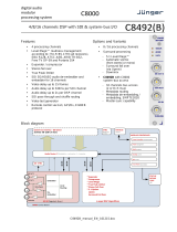
SYNNER 310 functional block diagram
SYNNER 310 User Manual R1.5 7 04 July 2019

Crystal Vision Introduction
Block Diagram Description
SDI video is cable-equalised, re-clocked and passed through a de-embedder block where up
to 16 channels of audio are extracted. The video signal is then processed allowing for
adjustment of video gain, black level and independent RGB and YUV gains. This is followed
by up to ten video frames of delay and optional synchronisation to an external video
reference. The video is then passed to the embedder block where up to 16 audio channels
are inserted.
All input audio from both external (up to 16 channels via the optional plug-in input piggyback)
and de-embedded sources (16 channels) are passed to audio processing blocks where gain
and fixed delay and/or automatic tracking delay for non Dolby-encoded signals, or alignment
delay for Dolby E signals are made after resampling.
The outputs of the audio processing block are input to two independent 32 x 16 routers which
feed the optional plug-in output piggybacks and the embedding block. In this way any of the
32 sources can be output or embedded.
Video and audio delays in SYNNER 310
SYNNER 310 has a variety of video and audio delays some of which are of fixed length and
others are dynamic.
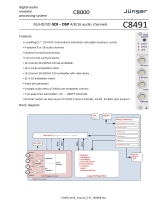
SYNNER 310 Delay Paths
When reference video is selected as the genlock source the video path is synchronised to an
external Black and Burst or tri-level reference and audio signals can optionally be made to
track this dynamic delay to maintain lip-sync. When the video input is the genlock source (i.e.
itself) the synchroniser is effectively bypassed and just the bulk delays active. In the following
description of delay blocks, the paragraph number refers to the delay block number in the
‘SYNNER 310 Delay Paths’ drawing above. The input signals in the Delay Paths block
diagram are from the de-embedder and external AES inputs. AES signals with Dolby E
encoding are treated differently to PCM signals. The output of the delay block goes to the
embedder and external output piggybacks.
1. This delay block will delay the video path by the value selected by the ‘Frame Delay’
control in the ‘Sync & Output Settings’ menu and can be from 0 to 10 frames. The
PCM and Dolby E audio signals will also be delayed by this amount if the appropriate
‘Frame Delay’ control is selected in the ‘Discrete Delay’ menu. This fixed delay is
SYNNER 310 User Manual R1.5 8 04 July 2019

Crystal Vision Introduction
useful for delaying the video with respect to the audio or to compensate for timing
errors elsewhere.
2. This block introduces a fixed delay to both video and PCM signals of either 0 or 0.5
frame depending on the value of ‘Min Sync Delay’ in the ‘Sync & Output Settings‘
menu. This delay can be useful to help overcome synchroniser disturbances and to
minimise Dolby E alignment delays.
If ‘Reference’ is selected as the genlock source in the ‘Sync & Output Settings menu,
the amount of delay through the following video frame synchroniser (see 6) will vary
according to the difference in timing between the video and reference signals and can
be anywhere from 0 to 1 frame. If the reference signal is not locked to the input video,
the synchroniser delay will increase or reduce to follow the reference. When the delay
goes beyond its minimum or maximum range it will jump instantaneously to the
opposite end of its range, either skipping or repeating a frame, possibly causing a
motion disturbance for non-static pictures. If the input video is nominally locked to the
reference but drifting slowly backwards and forwards or jittering, then it is sometimes
better to introduce an additional delay to the video path to centre the synchroniser
delay half-way through its range. Although the synchroniser control logic has
hysteresis to minimise this problem, in extreme cases of jitter the ‘Min Sync Delay’
delay can help give the synchroniser +/- 0.5 frame of dynamic delay adjustment
before hitting the end stops.
As Dolby E signals are not routed through this delay they will be advanced by up to
0.5 frames with respect to the video path. This can help minimise delays caused by
the alignment process (see 3).
3. Dolby E is sensitive to any disturbances to the data stream such as those introduced
during editing or routing. To overcome this, Dolby E includes a part of the signal
called the ‘guardband’ that is insensitive to disturbance and should be aligned with
the video switching point prior to editing, routing or synchronising. If ‘Dolby E Align’ is
selected in the ‘Discrete Delay’ menu, the alignment delay block will automatically
delay the Dolby signal by up to one frame to match the guardband and video switch
point. If the Dolby E channel is put through a series of embedding/de-embedding
sequences the alignment delay can be magnified to several frames but if the ‘Min
Sync Delay’ control is set to 0.5 frames the overall Dolby E delay with respect to the
video will be minimised.
4. If the ‘User Delay’ control in the ‘Discrete Delay’ menu is selected, this delay block
introduces a delay to PCM signals by the amount set by the ‘PCM Audio’ control from
-20 to +400mS. Note that for negative delay values at least one frame of video delay
and ‘Frame Delay’ must be selected as well.
5. If the ‘User Delay’ control in the ‘Discrete Delay’ menu is selected, this delay block
introduces a delay to Dolby E signals by the amount set by the ‘Dolby E’ control from -
14 to +36 samples. This range is chosen so the user cannot move the Dolby E
guardband away from the video switch point after alignment. Note that for negative
delay values at least one frame of video delay and ‘Frame Delay’ must be selected as
well.
6. If the genlock mode is set to ‘Reference’, this block synchronises the incoming video
signal to the external reference by setting a dynamic delay of up to one frame. If
Tracking Alignment Delay is selected by the ‘TAD Delay’ control in the ‘Discrete
Delay’ menu then the audio signals will be delayed by the same amount to maintain
lip-sync and Dolby E alignment.
7. If ‘TAD Delay’ is selected in the ‘Discrete Delay’ menu, this delay is slaved to the
video frame synchroniser to provide the same delay for PCM signals as the video
SYNNER 310 User Manual R1.5 9 04 July 2019

Crystal Vision Introduction
path. Variable delay is achieved by either resampling if ‘Resample’ is selected in the
‘Discrete Settings’ menu or audio sample drop/repeat if not.
8. If ‘TAD Delay’ is selected in the ‘Discrete Delay’ menu for Dolby E signals, this delay
will produce the same delay as the video frame synchroniser. Frames will be dropped
or repeated at the same time as the video. Dolby E encoded signals cannot be
resampled or samples dropped/repeated.
9. This delay is after the frame synchroniser and TAD delays. If ‘Reference’ is selected
as the genlock source, the values set by the ‘Line and Pixel Delay’ controls in the
‘Sync & Output Settings’ menu will delay the video and audio signals with respect to
the refererence. Otherwise this block will introduce a further delay to the video and
audio paths.
SYNNER 310 User Manual R1.5 10 04 July 2019

Crystal Vision Hardware installation
2 Hardware installation
Board configuration
SYNNER 310 main board top-side
Note: The potentiometers P1, P2, P3 and P4 have been factory set and should NOT be adjusted.
Holes marked ‘B’ are for the fitting of the I/O piggybacks.
Link Configuration
There are four user-settable links on the SYNNER 310. These are PL2-5, all other links should be
left in the position shown in the above picture. PL2-5 set whether the board’s GPI inputs are used
as GPIs or as an extra serial I/O port.
Link Towards front of board or Up Towards the rear of board or Down
J1 Sync input unterminated Sync input terminated by 75 ohm
J9 Debug mode – forces board’s IP address
to be 10.0.0.201
Normal mode (factory set, do not alter)
PL2
GPI 1 Input = RS422 Rx+
GPI 1 Input = GPI 1
PL3
GPI 2 Input = RS422 Rx-
GPI 2 Input = GPI 2
PL4
GPI 3 Input = RS422 Tx+
GPI 3 Input = GPI 3
PL5
GPI 4 Input = RS422 Tx-
GPI 4 Input = GPI 4
SYNNER 310 User Manual R1.5 11 04 July 2019

Crystal Vision Hardware installation
Input and output piggyback boards
The main SYNNER 310 board has two positions where one of three types of I/O module can
be plugged to enable analogue or digital input and output.
The three types of piggybacks are 3G-AIP2, 3G-AOP2 and DIOP4. The following table shows
the legal combinations of piggybacks that can be fitted into front and rear positions:
FRONT none DIOP4 3G-
AIP2 3G-
AOP2 DIOP4 DIOP4 DIOP4 3G-
AIP2 3G-
AIP2 3G-
AOP2
REAR none none none none DIOP4 3G-
AIP2 3G-
AOP2 3G-
AIP2 3G-
AOP2 3G-
AOP2
3G-AIP2 Analogue Input
This analogue module has four balanced audio inputs. The links PL1-4 allow 0dBFS to be set
to +18dBu (to the right, towards SK1) or +24dBu (to the left, towards SK2/3). The adjacent
potentiometers RV1-4 are factory set and should NOT be adjusted.
SYNNER 310 User Manual R1.5 12 04 July 2019

Crystal Vision Hardware installation
3G-AIP2 Channel number Link number
CH1 PL1
CH2 PL2
CH3 PL3
CH4 PL4
Table showing links controlling the input gain of the 3G-AIP2 channels
3G-AOP2 Analogue Output
This analogue piggyback has four balanced audio outputs. The links PL1-4 set 0dBFS to
+18dBu (to the right, towards SK2/3) or +24dBu (to the left, towards SK1). The four
potentiometers P1-P4 are factory set and should NOT be adjusted.
Table showing links controlling the output gain of the 3G-AOP2 channels
3G-AOP2 Channel number Link number
CH1 PL1
CH2 PL2
CH3 PL3
CH4 PL4
SYNNER 310 User Manual R1.5 13 04 July 2019

Crystal Vision Hardware installation
DIOP4 AES I/O
This digital audio piggyback has four AES stereo pairs that are individually configured as
inputs or outputs by software. There are no links or user-adjustments on this card.
Fitting the I/O piggybacks onto the main board
Example showing 3G-AIP2 and 3G-AOP2 piggybacks fitted
The I/O piggybacks plug onto the main board such that main board plugs J3, J4, J5 and J6,
J7, J8 align with piggyback sockets SK2, SK3, SK1. With the component side of the module
top-most, align the piggyback sockets carefully with the plugs and push firmly. Insert the
plastic rivets supplied with the fitting kit through the main board from the underside so they
protrude through the piggyback board, then push the rivet peg firmly to splay the end to lock
the piggyback board in position.
Note: The position that the piggyback is fitted determines the function of the rear module
connectors.
Front edge LEDs
LED1
LED2
LED3
LED4
LED5
On if power
supply OK On if Dolby not 5.1 On if error occurs
in audio content On if Vertical
frame sync error Bitstream Format
OFF= Dolby E,
ON = other
There are 13 links that are factory set and should NOT be moved.There is one potentiometer
P2 that is factory set and should NOT be adjusted.
SYNNER 310 User Manual R1.5 14 04 July 2019

Crystal Vision Rear modules and signal I/O
3 Rear modules and signal I/O
The 2U Indigo 2 frames will house up to 12 single height modules and dual power supplies.
The 1U Indigo 1 frames will house six single height modules and a single or dual power
supply. The Indigo DT desk top boxes have a built-in power supply and will house up to two
single height modules. All modules can be plugged in and removed while the frame is
powered without damage.
Note: For details of fitting rear connectors please refer to the appropriate frame manual.
The SYNNER 310 can support the following rear modules: RM47, RM58, RM59, RM61,
RM62, RM70 and RM74. The RM47, RM58 and RM59 are designed for 110 ohm operation
and the RM74 for 75 ohm operation.
Rear module connections with RM47
The RM47 being a single height module will allow maximum packing density with the
maximum number of outputs available. Eight AES stereo pairs or eight mono analogue
channels are presented as balanced I/O on the 26-way high density D-Type connector.
RM47 rear module connector
Description
RM47
• 12 per Indigo 2 frame
• Six per Indigo 1 frame
• Two per Indigo DT
• All frame slots can be
used
BNC connections
BNC I/O assignment
SDI IN 3G/High Definition/Standard Definition serial digital input
SYNC IN Analogue BlackBurst or tri-level sync reference for video synchroniser
SDI OUT(A) 3G/High Definition/Standard Definition serial digital output
SDI OUT(B) 3G/High Definition/Standard Definition serial digital output
26-way D-Type Audio Connections
The 26-way audio ‘D’ connector RM47 module can be used for analogue or digital, inputs or
outputs - or a mixture of both depending on the I/O piggybacks fitted. Half of the I/O channels
on the rear module are connected to the front I/O (nearest handle) piggyback position and the
remainder to the rear. The DIOP4 will normally be configured as 110 ohm balanced operation
when using this rear module.
SYNNER 310 User Manual R1.5 15 04 July 2019

Crystal Vision Rear modules and signal I/O
Module
position I/O Pin-out
GND 1
Analogue
audio 1/
AES1 { + 2
- 3
Analogue
audio 2/
AES2 { + 4
Front - 5
Analogue
audio 3/
AES3 { + 6
- 7
Analogue
audio 4/
AES4 { + 8
- 18
GND 9
Analogue
audio 5/
AES5 { + 14
- 15
Analogue
audio 6/
AES6 { + 10
Rear - 11
Analogue
audio 7/
AES7 { + 16
- 17
Analogue
audio 8/
AES8 { + 12
- 13
GND 19, 20,
23, 24
NC 21, 22,
25, 26
RM47 audio I/O connector wiring - All audio balanced signals can be either input or output
depending on I/O module fitted.
SYNNER 310 User Manual R1.5 16 04 July 2019

Crystal Vision Rear modules and signal I/O
Rear module connections with RM58
The RM58 being a single height module will allow maximum packing density with the option of
an optical connection. Eight AES stereo pairs or eight mono analogue channels are presented
as balanced I/O on the 26-way high density D-Type connector. Video output is optical only.
RM58 rear module connector
Description
RM58
• 12 per Indigo 2 frame
• Six per Indigo 1 frame
• Two per Indigo DT
• All frame slots can be
used
BNC Connections
BNC I/O assignment
SDI IN 3G/High Definition/Standard Definition serial digital input
SYNC IN Analogue Black and Burst or tri-level sync reference for video
synchroniser
OPTICAL I/O SC optical output connector
26-way D-Type Audio connections
The 26-way audio ‘D’ connector RM58 module can be used for analogue or digital, inputs or
outputs - or a mixture of both depending on the I/O piggybacks fitted. Half of the I/O channels
on the rear module are connected to the front I/O (nearest handle) piggyback and the
remainder to the rear. The DIOP4 will normally be configured as 110 ohm balanced operation
when using this rear module.
SYNNER 310 User Manual R1.5 17 04 July 2019

Crystal Vision Rear modules and signal I/O
Module
position I/O Pin-out
GND 1
Analogue
audio 1/
AES1 { + 2
- 3
Analogue
audio 2/
AES2 { + 4
Front - 5
Analogue
audio 3/
AES3 { + 6
- 7
Analogue
audio 4/
AES4 { + 8
- 18
GND 9
Analogue
audio 5/
AES5 { + 14
- 15
Analogue
audio 6/
AES6 { + 10
Rear - 11
Analogue
audio 7/
AES7 { + 16
- 17
Analogue
audio 8/
AES8 { + 12
- 13
GND 19, 20,
23, 24
NC 21, 22,
25, 26
RM58 audio I/O connector wiring - All audio balanced signals can be either input or output
depending on I/O module fitted.
SYNNER 310 User Manual R1.5 18 04 July 2019

Crystal Vision Rear modules and signal I/O
Rear module connections with RM59
The RM59 being a single height module will allow maximum packing density with the option of
an optical connection. Eight AES stereo pairs or eight mono analogue channels are presented
as balanced I/O on the 26-way high density D-Type connector. Video input is optical only.
RM59 rear module connector Description
RM59
• 12 per Indigo 2 frame
• Six per Indigo 1 frame
• Two per Indigo DT
• All frame slots can be used
BNC connections
BNC I/O assignment
SYNC IN Analogue Black and Burst or tri-level sync for video path synchroniser
SDI OUT 3G/High Definition/Standard Definition serial digital output
OPTICAL IN SC optical input connector
26-way D-Type audio connections
The 26-way audio ‘D’ connector RM59 module can be used for analogue or digital, inputs or
outputs - or a mixture of both depending on the I/O piggybacks fitted. Half of the I/O channels
on the rear module are connected to the front I/O (nearest handle) piggyback and the
remainder to the rear. The DIOP4 will normally be configured as 110 ohm balanced operation
when using this rear module.
SYNNER 310 User Manual R1.5 19 04 July 2019
/