Page is loading ...


Crystal Vision TANDEM 320 User Manual
Contents
1 Introduction 5
2 Hardware installation 7
Board configuration 7
Link configuration 7
Input and output piggyback boards 8
3G-AIP2 Analogue Input 8
3G-AOP2 Analogue Output 9
DIOP4 AES I/O 9
Fitting the I/O piggybacks onto the main board 10
3 Rear modules and signal I/O 11
Rear module connections with RM71 11
BNC connections 11
26-way D-Type Audio Connections 11
Rear module connections with RM72 13
BNC Connections 13
4 General Purpose Interface 14
Introduction 14
Alarms 16
2U frame GPI connections 16
1U frame GPI connections 17
Indigo DT desk top box GPI connections 17
5 Control and Status monitoring 18
Card edge controls 18
Card edge buttons 18
Card edge rotary control 18
Reading card edge LEDs 19
Navigating card edge menus 19
Using the front control panel 20
Selecting a TANDEM 320 20
Control Panel keys overview 21
TANDEM 320 User Manual R1.3 1 11 July 2019

Crystal Vision TANDEM 320 User Manual
Updating the display 21
Menu Structure 22
Controlling cards via VisionWeb 28
6 Control Descriptions 29
Status 30
Input A/B:Video Status 30
Input A/B:Audio Status 30
Input A:Front Sub PCB 31
Input B:Rear Sub PCB 31
Audio Settings 32
A/B:DeEmbedded Audio 32
A/B:Discrete AIP/AES Input Audio 33
A/B:Audio Gain 34
A/B:User Audio Delay Value 35
A/B:DeEmbedded Audio Delay 35
A/B:Discrete AIP/AES Input Audio Delay 36
A/B:AES I/O Configure 36
Audio Router 37
A/B:Embedder Router 37
A/B:Discrete (AES) Output Router 38
A/B:Discrete (Analog) Output Router 40
A/B:Mute & Group Enable 41
Presets, Resets & GPI/Os 42
Presets 42
Resets 43
A/B:Silence Alarm Delay 43
A/B:GPO Alarms 44
7 Troubleshooting 46
Card edge monitoring 46
Basic fault finding guide 46
8 Specification 47
9 Appendix 1 49
Statesman 49
Introduction 49
TANDEM 320 User Manual R1.3 2 11 July 2019

Crystal Vision TANDEM 320 User Manual
Statesman operation 49
Controls 50
Status 51
Video Status 51
SubPcb Type 51
Input Group Status 51
Output Group Status 51
Control 52
Embedded Audio 52
AES Audio 52
Audio Input 53
De-embedded Input 53
AES Audio Input 53
Audio Delay 54
De-embedded Audio Delay 54
AES Input Dly 54
Audio Delay 54
Audio Gain 55
Channel Gain 55
Embedder Router 56
OP Chs 56
Embed Mute 57
AOP Output Router 57
Audio Op Channels 57
Audio Op Mutes 58
AES Output Router 58
Audio Op Channels 58
Diop Mutes 59
GPO 59
GPO5/GPO6 59
Presets and Reset 60
Preset 60
Board Reset 61
TANDEM 320 User Manual R1.3 3 11 July 2019

Crystal Vision TANDEM 320 User Manual
Revision 1 Block diagram updated on page 5. 19/03/14
Revision 2 Clarified GPI section. Added VisionWeb. Moved Stateman
info to Appendix. 14/11/17
Revision 3 Added note about removal of card edge control in 2018. 11/07/19
TANDEM 320 User Manual R1.3 4 11 July 2019

Crystal Vision Introduction
1 Introduction
TANDEM 320 provides a versatile solution for audio embedding and de-embedding. It has a
dual SDI video path with a de-embedder and an embedder which allow the extraction, routing
and insertion of up to 16 channels (four groups) of audio per video channel.
Embedded audio signals can be extracted and output as analogue or AES, then re-sampled
and re-embedded into the video signal into the same or different channel position with user-
controlled gain and delay. Additionally, external analogue and AES audio inputs can be
embedded into the video signal in any channel position. Up to eight external audio channels
can be input and output per video channel.
There are two on-board plug-in locations for optional analogue and digital I/O piggybacks –
the front position for video channel A and the rear position for video channel B. Both video
channels support either AES I/O or analogue input or analogue output. It is not possible to
input and output analogue audio on the same video channel.
There are three types of piggyback: 3G-AIP2, 3G-AOP2 and DIOP4. The 3G-AIP2 piggyback
has four analogue inputs; 3G-AOP2 has four analogue outputs; DIOP4 has four stereo AES
pairs and each pair can be individually configured as an input or output. Most combinations of
piggyback type can be fitted into any of the two positions to provide the desired mixture of
analogue and AES, inputs and outputs (see section Input and output piggyback boards for
legal combinations).
The main features are as follows:
• Use with any source – works with 3Gb/s, HD and SD.
• Supports the following video standards: 625, 525, 720p50, 720p59.94, 1080i50,
1080i59.94, 1080p50, 1080p59.94, 1080psf23.98, 1080psf24.
• Versatile audio: will de-embed and embed up to four audio groups and input or output up
to four external AES stereo pairs or two analogue stereo pairs per video channel which
can be fully shuffled with the powerful audio routers.
• Optimise the audio: each channel has individual gain control and stereo to mono
conversion. The audio level can be increased or decreased to match the rest of the
system: each mono audio channel offers individual gain control, adjustable between
+18dB and -18dB in 0.1dB steps. Audio channels can be muted and stereo pairs
converted to mono. Audio channels can be delayed by up to 400mS.
• Control of TANDEM 320 can be by Crystal Vision’s VisionWeb web browser control
software, VisionPanel remote control panel, SNMP or an active front panel on the frame.
Card edge control was also available prior to 2018.
• GPI control of configuration set-ups and status alarms.
• Supports the following rear module connectors: RM71 for balanced analogue or AES
audio operation and RM72 for unbalanced AES audio operation.
• Compatible with Crystal Vision standard Indigo frames available in 2U, 1U and desk top
box.
• Passes all timecode, AFD and subtitling information.
TANDEM 320 User Manual R1.3 5 11 July 2019

Crystal Vision Introduction
.
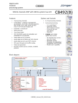
TANDEM 320 functional block diagram (one video channel shown only)
Block Diagram Description
SDI video is cable-equalised, re-clocked and passed through a de-embedder block where up
to 16 channels of audio are extracted.
All input audio from both external (up to eight channels via the optional plug-in input
piggyback) and de-embedded sources (16 channels) are passed to audio processing blocks
where gain and delay adjustments are made after re-sampling. Dolby E encoded signals
bypass the audio processing block.
The output of the audio processing block is an input to two independent routers which feed
the optional plug-in output piggyback and the embedding block as mono channels or stereo
pairs.
The video is then passed through the embedder block where up to 16 audio channels are
inserted.
TANDEM 320 User Manual R1.3 6 11 July 2019

Crystal Vision Hardware installation
2 Hardware installation
Board configuration
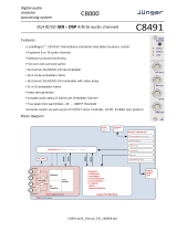
TANDEM 320 main board top-side
Note: The potentiometers P1, P2, P3 and P4 have been factory set and should NOT be adjusted.
Holes marked ‘B’ are for the fitting of the I/O piggybacks.
Link configuration
There are four user-settable links on the TANDEM 320. These are PL2-5; all other links
should be left in the position shown in the above picture. PL2-5 set whether the board’s
GPI inputs are used as GPIs or as an extra serial I/O port.
Link Towards front of board or Up Towards the rear of board or
Down
J1 JTAG bypassed (factory set, do not
alter)
J9
Debug mode
Normal mode (factory set, do not
alter)
PL2
GPI1 Input = GPI1
GPI1 Input = RS422 Rx+
PL3
GPI2 Input = GPI2
GPI2 Input = RS422 Rx-
PL4
GPI3 Input = GPI3
GPI3 Input = RS422 Tx+
PL5
GPI4 Input = GPI4
GPI4 Input = RS422 Tx-
TANDEM 320 User Manual R1.3 7 11 July 2019

Crystal Vision Hardware installation
Input and output piggyback boards
The TANDEM 320 PCB has two positions, one for each video channel, where one of three
types of I/O module can be plugged to enable analogue or digital, input or output.
The three types of piggybacks are 3G-AIP2, 3G-AOP2 and DIOP4. The following table shows
the only legal combinations of piggybacks that can be fitted into front and rear positions.
FRONT
Video
Ch. A
none DIOP4 3G-
AIP2 3G-
AOP2 DIOP4 DIOP4 DIOP4 3G-
AIP2 3G-
AIP2 3G-
AOP2
REAR
Video
Ch. B
none none none none DIOP4 3G-
AIP2 3G-
AOP2 3G-
AIP2 3G-
AOP2 3G-
AOP2
3G-AIP2 Analogue Input
This analogue module has four balanced audio inputs. The links PL1-4 allow 0dBFS to be set
to +18dBu (to the right, towards SK1) or +24dBu (to the left, towards SK2/3). The adjacent
potentiometers RV1-4 are factory set and should NOT be adjusted.
3G-AIP2 Channel number Link number
CH1 PL1
CH2 PL2
CH3 PL3
CH4 PL4
Table showing links controlling the input gain of the 3G-AIP2 channels
TANDEM 320 User Manual R1.3 8 11 July 2019

Crystal Vision Hardware installation
3G-AOP2 Analogue Output
This analogue piggyback has four balanced audio outputs. The links PL1-4 set 0dBFS to
+18dBu (to the right, towards SK2/3) or +24dBu (to the left, towards SK1). The four
potentiometers P1-P4 are factory set and should NOT be adjusted.
Table showing links controlling the output gain of the 3G-AOP2 channels
DIOP4 AES I/O
This digital audio piggyback has four AES stereo pairs that are individually configured as
inputs or outputs by software. There are no links or user-adjustments on this card.
3G-AOP2 Channel number Link number
CH1 PL1
CH2 PL2
CH3 PL3
CH4 PL4
TANDEM 320 User Manual R1.3 9 11 July 2019

Crystal Vision Hardware installation
Fitting the I/O piggybacks onto the main board
Example showing 3G-AIP2 and 3G-AOP2 piggybacks fitted
The I/O piggybacks plug onto the main board such that main board plugs J3, J4, J5 and J6,
J7, J8 align with piggyback sockets SK2, SK3, SK1. With the component side of the module
top-most, align the piggyback sockets carefully with the plugs and push firmly. Insert the
plastic rivets supplied with the fitting kit through the main board from the underside so they
protrude through the piggyback board, then push the rivet peg firmly to splay the end to lock
the piggyback board in position.
Note: The type of piggyback fitted determines the function of the rear module
connectors.
TANDEM 320 User Manual R1.3 10 11 July 2019

Crystal Vision Rear modules and signal I/O
3 Rear modules and signal I/O
The 2U Indigo 2 frames will house up to 12 single height modules and dual power supplies.
The 1U Indigo 1 frames will house six single height modules and a single or dual power
supply. The Indigo DT desk top boxes have a built-in power supply and will house up to two
single height modules. All modules can be plugged in and removed while the frame is
powered without damage.
Note: For details of fitting rear connectors please refer to the appropriate frame manual.
TANDEM 320 can support the following rear modules: RM71 and RM72.
Rear module connections with RM71
The RM71 being a single height module will allow maximum packing density with the
maximum number of outputs available. Eight channels of audio AES stereo pairs or eight
mono analogue channels are presented as balanced I/O on the 26-way high density D-Type
connector.
RM71 rear module connector
Description
RM71
• 12 per Indigo 2 frame
• Six per Indigo 1 frame
• Two per Indigo DT
•
All frame slots can be used
BNC connections
BNC I/O assignment
HD/SD IN 1 3G/High Definition/Standard Definition serial digital input channel A
HD/SD IN 2 3G/High Definition/Standard Definition serial digital input channel B
HD/SD OUT 1 3G/High Definition/Standard Definition serial digital output channel A
HD/SD OUT 2 3G/High Definition/Standard Definition serial digital output channel B
26-way D-Type Audio Connections
The 26-way audio ‘D’ connector RM71 module can be used for analogue or digital, inputs or
outputs – or a mixture of both depending on the I/O modules fitted. Half of the I/O channels on
the rear module are connected to the front I/O (nearest handle) module position (video
channel A) and the remainder to the rear module position (video channel B). The DIOP4 will
normally be configured as 110 ohm balanced operation when using this rear module.
TANDEM 320 User Manual R1.3 11 11 July 2019

Crystal Vision Rear modules and signal I/O
Module position I/O Pin-out
GND 1
Analogue
audio 1/
AES1 { + 2
- 3
Analogue
audio 2/
AES2 { + 4
Front Video
Ch. A
- 5
Analogue
audio 3/
AES3 { + 6
- 7
Analogue
audio 4/
AES4 { + 8
- 18
GND 9
Analogue
audio 5/
AES5 { + 14
- 15
Analogue
audio 6/
AES6 { + 10
Rear Video
Ch.B
- 11
Analogue
audio 7/
AES7 { + 16
- 17
Analogue
audio 8/
AES8 { + 12
- 13
GND 19, 20,
23, 24
NC 21, 22,
25, 26
RM71 audio I/O connector wiring - All audio balanced signals can be either input or output
depending on I/O module fitted.
TANDEM 320 User Manual R1.3 12 11 July 2019

Crystal Vision Rear modules and signal I/O
Rear module connections with RM72
The RM72 is a dual height module presenting the eight channels of unbalanced audio AES
stereo pairs on 75 ohm BNC connectors. The DIOP4 I/O module(s) must be used with this
rear module as there is no provision for analogue audio I/O.
RM72 rear module connector
Description
RM72
• Six per Indigo 2 frame
• Three per Indigo 1 frame
• One per Indigo DT
• Alternate frame slots can be
used
BNC Connections
BNC I/O assignment
HD/SD IN 1 3G/High Definition/Standard Definition serial digital input channel A
AES8 I/O AES8 stereo pair 75 ohm input/output
AES4 I/O AES4 stereo pair 75 ohm input/output
HD/SD IN 2 3G/High Definition/Standard Definition serial digital input channel B
HD/SD OUT 1 3G/High Definition/Standard Definition serial digital output channel A
HD/SD OUT 2 3G/High Definition/Standard Definition serial digital output channel B
AES6 I/O AES6 stereo pair 75 ohm input/output
AES5 I/O AES5 stereo pair 75 ohm input/output
AES7 I/O AES7 stereo pair 75 ohm input/output
AES3 I/O AES3 stereo pair 75 ohm input/output
AES2 I/O AES2 stereo pair 75 ohm input/output
AES1 I/O AES1 stereo pair 75 ohm input/output
TANDEM 320 User Manual R1.3 13 11 July 2019

Crystal Vision General Purpose Interface
4 General Purpose Interface
Introduction
Each frame slot has up to six connections ‘a-f’ for GPI control and monitoring. These
connections are available at the rear of the frame on the 26-way D-Type remote connectors.
TANDEM 320 has four GPI inputs and two GPI outputs. GPO5 is triggered by video channel
A alarm conditions and GPO6 by video channel B.
Each General Purpose Interface (GPI) input is fitted with a 10kΩ resistor connected to the
internal +5V and in the following table, this equates to logic ‘H’. With the GPI preset recall
lines set to ‘level’ mode and no connections (logic ‘HHHH’), preset 1 will be selected. With the
GPI preset recall lines are set to ‘pulse’ mode, the GPI will be activated whenever a bit is
pulled low but no change to the preset selection will occur when all bits return to logic ‘HHHH’.
Note that preset 16 is not accessible in pulse mode.
Note: Because the GPI inputs are sampled in the vertical interval it is recommended that in
‘pulse’ mode, the GPI should be asserted at least 2mS before the start of vertical sync to
ensure stability and held active for at least 40mS.
See Presets in this manual for details of inverting the GPI preset logic.
Each General Purpose Interface (GPI) output has a 270Ω resistor in series with its output.
This allows for an external LED to be driven, connected to a DC voltage of +5V.
The GPI inputs can be programmed to automatically recall a previously saved preset
configuration. The 16 user preset configurations are selected using binary notation. The two
outputs can be programmed to assert themselves for a number of different alarm conditions.
GPI Low (<1V) High (+5V)
1
‘a’
Recall preset bit 1
See following table for user preset control
2 ‘b’ Recall preset bit 2
3 ‘c’ Recall preset bit 4
4 ‘d’ Recall preset bit 8
5 ‘e’ Alarms (See alarm table) Alarm condition No alarm
6 ‘f’ Alarms (See alarm table) Alarm condition No alarm
Table showing the six GPI functions
TANDEM 320 User Manual R1.3 14 11 July 2019

Crystal Vision General Purpose Interface
GPI Bit 8 Bit 4 Bit 2 Bit 1
Preset
1
H
H
H
H
2
H
H
H
L
3
H
H
L
H
4
H
H
L
L
5
H
L
H
H
6
H
L
H
L
7
H
L
L
H
8
H
L
L
L
9
L
H
H
H
10
L
H
H
L
11
L
H
L
H
12
L
H
L
L
13
L
L
H
H
14
L
L
H
L
15
L
L
L
H
16
L
L
L
L
Binary coding of GPI inputs to recall preset configurations in level mode
GPI
Bit 8
Bit 4
Bit 2
Bit 1
Preset
No change
1
2
3
4
5
6
7
8
9
10
11
12
13
14
15
16
Not accessible in pulse mode.
Binary coding of GPI inputs to recall preset configurations in pulse mode
TANDEM 320 User Manual R1.3 15 11 July 2019

Crystal Vision General Purpose Interface
Alarms
GPI Out 5 and 6 (e, f) can be configured to be asserted (logic ‘L’) for a selection of error
conditions.
For each GPO there are a maximum of 35 separate alarm conditions. The following table lists
the maximum number of alarms available. Some alarm conditions are not available if the
optional AES DIOP4 piggyback(s) are not fitted. See Control Descriptions for more details of
alarms.
Reportable error conditions No. of
alarms
Video Missing 1
Video Black 1
Video Frozen 1
Input groups 1-4 missing 4
Channel pair silent for all groups 8
Channel pair has Dolby E encoding present for all groups 8
AES channel pair input missing for all fitted DIOP4 piggybacks 4 (max)
AES channel pair input silent for all fitted DIOP4 piggybacks 4 (max)
AES channel pair has Dolby E encoding for all fitted DIOP4 piggybacks 4 (max)
Alarms Table
2U frame GPI connections
GPI lines ‘a’ to ‘f’ of each card connect to two of four rear remote connectors as follows:
Slot no.
‘a’ pin
‘b’ pin
‘c’ pin
‘d’ pin
‘e’ pin
‘f’ pin
1
8 (1)
9 (1)
18 (1)
26 (1)
19 (2)
20 (2)
2
7 (1)
16 (1)
17 (1)
25 (1)
10 (2)
11 (2)
3
8 (3)
9 (3)
18 (3)
26 (3)
19 (4)
20 (4)
4
7 (3)
16 (3)
17 (3)
25 (3)
10 (4)
11 (4)
5
5 (1)
6 (1)
15 (1)
24 (1)
1 (2)
2 (2)
6
4 (1)
14 (1)
13 (1)
23 (1)
3 (2)
4 (2)
7
5 (3)
6 (3)
15 (3)
24 (3)
1 (4)
2 (4)
8
4 (3)
14 (3)
13 (3)
23 (3)
3 (4)
4 (4)
9
3 (1)
12 (1)
22 (1)
21 (1)
12 (2)
13 (2)
10
10 (1)
11 (1)
19 (1)
20 (1)
21 (2)
22 (2)
11
3 (3)
12 (3)
22 (3)
21 (3)
12 (4)
13 (4)
12
10 (3)
11 (3)
19 (3)
20 (3)
21 (4)
22 (4)
Table shows pin number (remote number)
Note:
Remote 1 and Remote 3 are 26-way high-density D-Type female sockets. Frame
ground is pin 2 and +5V @500mA is pin 1 in each case.
Remote 2 and Remote 4 are 26-way high-density D-Type male plugs and frame
ground is pin 6 in each case and +5V @500mA is pin 15 on Remote 2.
Note: The +5V output is protected by self-resetting thermal fuses, which limit the
total output current available from Remotes 1-4 to approximately 1A.
TANDEM 320 User Manual R1.3 16 11 July 2019

Crystal Vision General Purpose Interface
1U frame GPI connections
GPI lines ‘a’ to ‘f’ of each card connect to two rear remote connectors as follows:
Slot no.
‘a’ pin
‘b’ pin
‘c’ pin
‘d’ pin
‘e’ pin
‘f’ pin
1
8 (1)
9 (1)
18 (1)
26 (1)
19 (2)
20 (2)
2
7 (1)
16 (1)
17 (1)
25 (1)
10 (2)
11 (2)
3
5 (1)
6 (1)
15 (1)
24 (1)
1 (2)
2 (2)
4
4 (1)
14 (1)
13 (1)
23 (1)
3 (2)
4 (2)
5
3 (1)
12 (1)
22 (1)
21 (1)
12 (2)
13 (2)
6
10 (1)
11 (1)
19 (1)
20 (1)
21 (2)
22 (2)
Table shows pin number (remote number)
Note:
Remote 1: 26-way high-density D-Type female socket. Frame ground is pin 2
and +5V @500mA is pin 1.
Remote 2: 26-way high-density D-Type male plugs and frame ground is pin 6
and +5V @500mA is pin 15.
Note: The +5V output is protected by self-resetting thermal fuses, which limit
the total output current available from Remotes 1-2 to approximately 1A.
Indigo DT desk top box GPI connections
GPI lines ‘a’ to ‘f’ of each card connect to two rear remote connectors as follows:
Slot no.
‘a’ pin
‘b’ pin
‘c’ pin
‘d’ pin
‘e’ pin
‘f’ pin
1
8 (1)
9 (1)
18 (1)
26 (1)
19 (2)
20 (2)
2
7 (1)
16 (1)
17 (1)
25 (1)
10 (2)
11 (2)
Table shows pin number (remote number)
Note:
Remote 1: 26-way high-density D-Type female socket. Frame ground is pin 2
and +5V @500mA is pin 1.
Remote 2: 26-way high-density D-Type male plugs and frame ground is pin 6
and +5V @500mA is pin 15.
Note: The +5V output is protected by self-resetting thermal fuses, which limit
the total output current available from Remotes 1-2 to approximately 1A.
TANDEM 320 User Manual R1.3 17 11 July 2019

Crystal Vision Control and Status monitoring
5 Control and Status monitoring
TANDEM 320 controls and status can be accessed by either the card edge control, the rack
front panel, ‘VisionPanel’ remote panel or by ‘VisionWeb’ remote control PC software.
TANDEM 320 is aware of what optional boards are fitted and adjusts the card edge/front
panel menu tree accordingly to reflect the options available. For instance, if no audio I/O
piggybacks are fitted, then no provision is shown for selecting those audio sources or outputs.
Similarly, the VisionWeb GUI also only shows the functionality of the fitted options.
Board edge control was removed from TANDEM 320 in 2018. Therefore the card edge control
information detailed below is only relevant for older versions of the product.
Card edge controls
TANDEM 320 board edge
Card edge buttons
The two tactile push button switches allow the operator to navigate within the menu structure.
.
Button Function Normal state Up, Action Down
Up Menu Push to jump up a menu level or cancel a selection
ENTER Select/Action Push to select a menu and to action and confirm a change
Card edge rotary control
The board edge rotary encoder is used to navigate through the menu categories and adjust
parameter values.
Control Function
SCROLL/
ADJ
Rotate SCROLL/ADJ to identify a menu category. In combination with the
ENTER button, select and ADJUST to change the current level or select a
further option.
Note: The rotary control can access menus and parameter values by clockwise or anti-
clockwise rotation.
TANDEM 320 User Manual R1.3 18 11 July 2019

Crystal Vision Control and Status monitoring
Reading card edge LEDs
Card edge LEDs may be used in conjunction with status information from any connected
remote status panel display or from VisionWeb if available.
Refer also to the troubleshooting chapter for more help with solving problems and monitoring
status information.
The following table summarises the card edge LED functions and colours:
LED Name
#
LED
Colour
Function when ON Function when Off
1 PSU Green Good power supply (PSU) rails
One or more of the monitor
supplies is out of specification
2 Lock Green
3 HD Yellow Video input A standard is HD
(High Definition) Input not present
4 SD Yellow
Video input A standard is SD
(Standard Definition)
5 HD Yellow Video input B standard is HD
(High Definition)
Input not present
6 SD Yellow
Video input B standard is SD
(Standard Definition)
7
G1
Yellow
Audio Group 1 present Ch. A
Audio Group 1 not present
8
G2
Yellow
Audio Group 2 present Ch. A
Audio Group 2 not present
9
G1
Yellow
Audio Group 1 present Ch. B
Audio Group 1 not present
10
G2
Yellow
Audio Group 2 present Ch. B
Audio Group 2 not present
Navigating card edge menus
To access the card edge menu system proceed as follows:
• Press the up-arrow [ ] until a top menu category is reached
• Rotate the SCROLL/ADJ control until the desired menu category is found
• Press ENTER to enter the sub-menus of that category
• Rotate SCROLL/ADJ to select a sub-menu
• Press ENTER to select the desired function. Selection will be indicated by the text
being displayed in italic text
• Rotate ADJUST to make the desired change to the selected parameter. The display
changes to italics to indicate that a change has been made and requires confirmation
• When required push ENTER to action the change. The display will return to normal
non-italic text.
• Use the up-arrow [ ] and SCROLL/ADJ control to navigate to further menus
TANDEM 320 User Manual R1.3 19 11 July 2019
/