Page is loading ...

Outdoor Enclosure
Assembly Instructions

Multicomp Pro
Assembly Instructions
2
Contents
Contents ................................................................................................................................................ 2
Gore Vent Installation ............................................................................................................................ 3
N-Type Component Installation ............................................................................................................. 3
M25 Module Installation (GLB & Formosa) ............................................................................................ 3
M25 Module Installation (AC) ................................................................................................................ 4
M25 Power Module Installation ............................................................................................................ 5
M25 Knurled Cover Installation ............................................................................................................. 5
M25 Plastic Cover Installation ............................................................................................................... 5
PCB Installation ...................................................................................................................................... 5
Cable Installation ................................................................................................................................... 6
Metal Lid Assembly ................................................................................................................................ 6
Plastic Lid Assembly ............................................................................................................................... 7
Accessories ............................................................................................................................................ 7
Field-side Power Connector Installation ................................................................................................ 7
Mounting Brackets ........................................................................................................................... 8
Option 1 MPGLBAC-WALLMOU-SUS-M Installation Guide ....................................................... 8
Mounting Installation Package Content ................................................................................... 8
Install Enclosure On The Pole Mount Vertical .......................................................................... 9
Install Enclosure On The Pole Mount Horizontal...................................................................... 9
Mounting for Pole .................................................................................................................... 9
Option 2 MPGTT-ACC-P025KA-M Installation Guide ................................................................. 9
Mounting Installation Package Content ................................................................................... 9
Install Enclosure On The Articulation Pole ............................................................................. 10
Mount For Wall ...................................................................................................................... 10
Mounting For Pole ................................................................................................................. 10
Mounting For Pole Less Than 1.5” (35mm) ......................................................................... 10
Mounting For Pole Larger Than 1.5” (35mm) and Less Than 3” (80mm) ............................ 10
Mounting For Pole Larger Than 3” (80 mm) ........................................................................ 11
Install Enclosure on The Pole .................................................................................................... 11
How to Install Antenna .................................................................................................................. 11

Multicomp Pro
Assembly Instructions
3
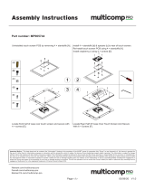
The enclosure shown in the diagrams below is the GLB 3600. Part assembly is compatible with
other enclosure models unless otherwise specified.
Gore Vent Installation
Gently screw in the vent by hand to ensure it is
not cross threaded, and once hand tight fully
tighten using a 16mm hex socket torque
wrench 0.59-0.78 N.m. Ensure the hex socket is
vertically aligned with the vent before
tightening.
All N-Type Component Installation
1. Ensure the red gasket ring is in situ on
the N Type bulkhead connector.
2. Insert the bulkhead connector into the
N-Type hole from the outside of the
enclosure.
3. Slide the washer and then the nut over
the cable (if fitted) from inside the
enclosure.
4. Gently screw on the nut by hand to
ensure it is not cross threaded, and
once hand tight fully tighten using a
20mm torque wrench to 1.96-2.15 N.m.

Multicomp Pro
Assembly Instructions
4
M25 Module Installation (GLB & Formosa)
1. Fit the mSmart® plastic modules
onto a pair of the threaded
standoffs on the internal
mounting bracket using the
supplied screws. Tighten using a
PH2 drive bit to a torque setting
of 0.49-0.58 N.m.
2. Place the mounting bracket in the
enclosure and push firmly against
the front of enclosure.
3. Fit the mounting bracket into the
enclosures using the supplied
screws and tighten using a PH2
drive bit to a torque setting of
0.49-0.58 N.m.
M25 Module Installation (AC)
1. Fit the mounting bracket into the
enclosures in front of the chosen M25
opening using the supplied screws and
tighten using a PH2 drive bit to a
torque setting of 0.49-0.48 N.m.

Multicomp Pro
Assembly Instructions
5
2. Fit the mSmart® plastic module onto
the pair of threaded standoffs on the
mounting bracket using the supplied
screws. Tighten using a PH2 drive bit to
a torque setting of 0.49-0.58 N.m.
M25 Power Module Installation
NB: prior to assembly ensure cable
termination is complete.
1. Ensure the supplied O-Ring is seated
correctly over the threaded section of
the M25 module.
2. Gently screw the power module into
the desired M25 location by hand.
Tighten the power module using a
32mm open ended torque wrench to a
torque setting of 2.75-2.94 N.m.
M25 Knurled Cover Installation
Ensure the supplied O-Ring is seated correctly
over the threaded section of the cover, then
screw the cover into the desired M25 location.
Recommended torque 0.49-0.58N.m.
M25 Plastic Cover Installation
Ensure the supplied O-Ring is seated correctly
over the threaded section of the cover, then
screw the cover into the desired M25 location.
Tighten initially by hand and then using a 25mm
hex socket wrench. Be careful not to
overtighten, as it can cause the O-Ring to
become mis-aligned. Recommended torque
0.49-0.58N.m.

Multicomp Pro
Assembly Instructions
6
PCB Installation
Install the PCB adapter plate by aligning the
holes in the plate with the screw bosses in the
enclosure. Secure the plate using the supplied
screws and tighten using a PH2 drive bit to a
torque setting of 0.39-0.49 N.m.
Cable Installation
Install the cable/s onto the corresponding M25
module/s ensuring that you support each
modules PCB element when applying pressure
connecting the cable to prevent damage.
PCB Adaptor Plate

Multicomp Pro
Assembly Instructions
7
Metal Lid Assembly
1. Place the lid on the enclosure ensuring
it is correctly located all around. Fit all
the supplied screws loosely using a
PH2 drive bit to hold the lid in place.
2. Tighten the lid screws in a diagonal
sequence until all the screws are hand
tight. Refer to the screw numbers in
the image, for an example sequence.
3. Fully tighten the screws to the torque
settings below
4. AC = 0.78-0.98 N m.
GLB = 0.78-0.98 N m.
Formosa = 0.78-0.98 N m.
Plastic Lid Assembly
1. Place the lid on the enclosure ensuring it
is correctly located all around. Fit all the
supplied screws loosely using a PH2 drive
bit to hold the lid in place.
2. Tighten the lid screws in a diagonal
sequence until all the screws are hand
tight. Refer to the screw numbers in the
image, for an example sequence.
3. Fully tighten the screws to the torque AC
= 0.59-0.78 N m.
GLB = 0.98-1.17 N m

Multicomp Pro
Assembly Instructions
8
Accessories
Field-side Power Connector Installation
Insert the cable through the Sealing Nut (i), Cable clip (ii), Sealing (iii), Sealing Body (iv), Gasket (v)
and Lock Nut (vi)
Fix the core wire/s into the screw fixing points of the connector with a 1.5mm tip flat bladed
screwdriver
a. Follow Fit the Gasket (v), Sealing (iii) and Cable clip (ii) onto the Sealing Body (iv)
b.
Fit the Lock Nut (vi) and O-ring (ix) onto the Housing (vii)
Screw the Sealing Nut (i) and the assembled Housing (x) onto the assembled Sealing Body (xi) with
a torque force of 8~10kfg-cm.
Completed Assembly

Multicomp Pro
Assembly Instructions
9
Mounting Brackets
Option 1 MPGLBAC-WALLMOU-SUS-M Installation Guide
Mounting Installation Package Content
• Wall Mount x 1
• Stainless back straps x 2
• M6x12 Screw x 4
• Washer x 4
• Spring Washer x 4
Install Enclosure On The Pole Mount Vertical
Attach the Pole mount to back of the
enclosure using M6x12 screws & washers.
Tighten bolts and washer with a torque of 2 N
m.
Install Enclosure On The Pole Mount Horizontal
Attach the Pole mount to back of the
enclosure using M6x12 screws & washers.
Mounting for Pole
Fix the Pole mount with enclosure to the pole
using stainless tie back straps.

Multicomp Pro
Assembly Instructions
10
Option 2 MPGTT-ACC-P025KA-M Installation Guide
Mounting Installation Package Content
• Articulation Pole x 1
• T-Form Bracket x 1
• W-Bar x 1
• M8x80 Screw Bolts x 2
• M8x90 Screw Bolts x 1
• M6x16 Screws x 4
• Nut x 1
• Washer x 4
• Spring Washer x 4
• Wood Screw x 4
• Wood / Gyprock Plug x 4
Install Enclosure On The Articulation Pole
Attach the articulation pole to back of GLB
using M6x16 screws & washers. Tighten
bolts and washer with a torque of 2 N m.
Mount For Wall
Fix the mount base to the wall using
appropriate fixings screws.

Multicomp Pro
Assembly Instructions
11
Mounting For Pole
Mounting For Pole Less Than 1.5” (35mm)
Attach mount base and W-bar to pole as shown
using M8x80 bolts and washer with a torque of
7 N m.
NB: Tighten the screws in parallel, otherwise
damage to w-bar may occur.
Mounting For Pole Larger Than 1.5” (35mm) and
Less Than 3” (80mm)
Attach mount base and W-bar to pole as shown
using M8x80 bolts and washer with a torque of
7 N m.
NB: Tighten the screws in parallel, otherwise
damage to w-bar may occur.
Mounting For Pole Larger Than 3” (80 mm) Fix
the mount base to the pole using stainless tie
back straps.
NB: Stainless tie straps not supplied.
Install Enclosure on The Pole
Attach the articulation pole to the
mount base articulation using a M8x90
bolt, nut and washers.

Multicomp Pro
Assembly Instructions
12
How to Install Antenna
Grip the antenna at the base then tighten
by hand until home. Tightening at the tip
may cause damage to your unit resulting
in signal degradation.
NB: Dropping, bending, and impacting
antenna can cause damage – handle
with care.
/