Page is loading ...

Copyright © Innovative Technology Ltd 2020 Doc: GA02185 User Manual CBA Range
Version:2.1
CBA
Range
GA02185
User Manual

User Manual CBA Range
<< Back to Contents
Copyright © Innovative Technology Ltd 2020 Doc: User Manual CBA Range
Version:2.1
Page 1 of 66
Document Name:
CBA9 Range User Manual
Document Version:
2.1
Date of Release:
20.10.2020
TABLE OF CONTENTS
1 DOCUMENT INTRODUCTION .................................................................................................................. 4
1.1 CONTACT INFORMATION ................................................................................................................................. 4
1.2 RELATED DOCUMENTS ................................................................................................................................... 4
1.3 MANUAL AMENDMENTS ................................................................................................................................. 4
1.4 COPYRIGHT .................................................................................................................................................. 4
1.5 LIMITED WARRANTY ...................................................................................................................................... 6
1.6 PRODUCT SAFETY INFORMATION ...................................................................................................................... 7
1.7 DISCLAIMER ................................................................................................................................................. 7
2 PRODUCT INTRODUCTION ...................................................................................................................... 9
2.1 GENERAL DESCRIPTION ................................................................................................................................... 9
2.2 KEY FEATURES .............................................................................................................................................. 9
2.3 TYPICAL APPLICATIONS ................................................................................................................................... 9
2.4 COMPONENT OVERVIEW ................................................................................................................................ 9
2.5 BEZEL OPTIONS ........................................................................................................................................... 10
2.6 CASHBOX OPTIONS ...................................................................................................................................... 11
3 MECHANICAL INSTALLATION ................................................................................................................ 12
3.1 COMPATIBILITY ........................................................................................................................................... 12
3.1.1 Hardware Compatibility ................................................................................................................ 12
3.1.1.1 Machine Mounting ................................................................................................................................... 12
3.1.1.2 Machine Interfacing ................................................................................................................................. 12
3.1.1.3 Power Supply ........................................................................................................................................... 13
3.1.2 Software Compatibility ................................................................................................................. 13
3.1.2.1 Interface Protocols ................................................................................................................................... 13
3.1.2.2 Re-programming ...................................................................................................................................... 13
3.2 BEZEL/NOZZLE MOUNTING ........................................................................................................................... 14
3.2.1 Bezel/Nozzle Fitting ...................................................................................................................... 14
3.2.2 Bezel/Nozzle Removal .................................................................................................................. 15
3.3 CASHBOX/BASEPLATE MOUNTING .................................................................................................................. 16
3.3.1 Cashbox/Baseplate Fitting ............................................................................................................ 16
3.3.2 Cashbox Removal .......................................................................................................................... 17
3.4 LOCK MOUNTING ........................................................................................................................................ 19
3.4.1 Lock Fitting .................................................................................................................................... 19
3.4.2 Lock Specifications ........................................................................................................................ 20
3.4.3 Lock Cam ....................................................................................................................................... 20
3.5 MACHINE MOUNTING .................................................................................................................................. 21
3.5.1 Machine Mounting ....................................................................................................................... 21
3.5.2 Earth Bonding ............................................................................................................................... 21
4 SOFTWARE INSTALLATION AND CONFIGURATION ................................................................................ 22
4.1 INTRODUCTION ........................................................................................................................................... 22
4.2 SOFTWARE DOWNLOADS .............................................................................................................................. 22
4.3 DRIVERS .................................................................................................................................................... 22
4.4 DATASET/FIRMWARE PROGRAMMING ............................................................................................................ 22
4.4.1 Validator Manager ........................................................................................................................ 22

User Manual CBA Range
<< Back to Contents
Copyright © Innovative Technology Ltd 2020 Doc: User Manual CBA Range
Version:2.1
Page 2 of 66
4.4.1.1 General Description ................................................................................................................................. 22
4.4.1.2 System Requirements .............................................................................................................................. 22
4.4.1.3 Hardware Setup ....................................................................................................................................... 23
4.4.1.4 Switching to Programming Mode (SSP) .................................................................................................... 23
4.4.1.5 Programming the device .......................................................................................................................... 24
4.4.2 DA3 ............................................................................................................................................... 25
4.4.2.1 General Description ................................................................................................................................. 25
4.4.2.2 System Requirements .............................................................................................................................. 25
4.4.2.3 Re-programming via DA3 ......................................................................................................................... 25
4.4.3 Remote Updates ........................................................................................................................... 26
4.4.3.1 Gereral Description .................................................................................................................................. 26
4.4.3.2 Software Requirements ........................................................................................................................... 26
5 PROTOCOLS AND INTERFACING ............................................................................................................ 27
5.1 INTRODUCTION ........................................................................................................................................... 27
5.2 SSP AND ESSP ........................................................................................................................................... 27
5.2.1 General Description ...................................................................................................................... 27
5.2.2 Pin Assignments ............................................................................................................................ 27
5.2.3 Setup Examples ............................................................................................................................. 28
5.3 CCTALK
®
.................................................................................................................................................... 29
5.3.1 General Description ...................................................................................................................... 29
5.3.2 Pin Assignments ............................................................................................................................ 30
5.3.3 ccTalk
®
DES Encryption .................................................................................................................. 31
5.4 CC4 ......................................................................................................................................................... 32
5.4.1 General Description ...................................................................................................................... 32
5.4.2 Pinout ............................................................................................................................................ 32
5.5 SIO AND SI2 .............................................................................................................................................. 34
5.5.1 General Description ...................................................................................................................... 34
5.5.2 Pinout ............................................................................................................................................ 34
5.6 MDB ........................................................................................................................................................ 36
5.6.1 General Description ...................................................................................................................... 36
5.6.2 IF5 Interface .................................................................................................................................. 36
5.7 PARALLEL ................................................................................................................................................... 37
5.7.1 General Description ...................................................................................................................... 37
5.7.2 Pinout ............................................................................................................................................ 37
5.7.3 Inhibit Control ............................................................................................................................... 38
5.7.4 Escrow Control .............................................................................................................................. 38
5.7.5 IF10 Interface ................................................................................................................................ 38
5.8 BINARY ...................................................................................................................................................... 39
5.8.1 General Description ...................................................................................................................... 39
5.8.2 Pinout ............................................................................................................................................ 39
5.8.3 Inhibit Control ............................................................................................................................... 40
5.8.4 Escrow Control .............................................................................................................................. 40
5.8.5 IF9 Interface .................................................................................................................................. 40
5.9 PULSE ....................................................................................................................................................... 41
5.9.1 General Description ...................................................................................................................... 41
5.9.2 Pinout ............................................................................................................................................ 41
5.9.3 Inhibit Control ............................................................................................................................... 42
5.9.4 Escrow Control .............................................................................................................................. 42
5.9.6 IF15 Interface ................................................................................................................................ 42
6 ROUTINE MAINTENANCE ...................................................................................................................... 43
6.1 INTRODUCTION ........................................................................................................................................... 43
6.2 RECOMMENDED CLEANING INTERVALS ............................................................................................................ 43
6.3 RECOMMENDED BELT CHANGING INTERVALS .................................................................................................... 43

User Manual CBA Range
<< Back to Contents
Copyright © Innovative Technology Ltd 2020 Doc: User Manual CBA Range
Version:2.1
Page 3 of 66
7 FIRST LEVEL SUPPORT ........................................................................................................................... 44
7.1 BEZEL/STATUS LED FLASH CODES .................................................................................................................. 44
7.2 STATUS LED FLASH CODES ............................................................................................................................ 45
7.3 CONFIGURATION BUTTON ............................................................................................................................. 45
8 SECOND LEVEL SUPPORT ...................................................................................................................... 47
8.1 INTRODUCTION ........................................................................................................................................... 47
8.2 FAULT FINDING FLOW CHART ........................................................................................................................ 47
8.3 CLEARING A JAM ......................................................................................................................................... 48
8.4 CLEANING THE CBA ..................................................................................................................................... 49
8.5 CHANGING THE DRIVE BELTS ......................................................................................................................... 50
8.6 CLEARING A CHECKSUM ERROR ...................................................................................................................... 51
8.7 TESTING AFTER AN ERROR HAS BEEN CLEARED ................................................................................................... 51
8.8 RE-INITIALISATION OF THE SENSORS ................................................................................................................ 52
9 TECHNICAL DATA .................................................................................................................................. 53
9.1 DIMENSIONS .............................................................................................................................................. 53
9.2 WEIGHT .................................................................................................................................................... 53
9.3 ENVIRONMENTAL REQUIREMENTS .................................................................................................................. 53
9.4 POWER REQUIREMENTS ............................................................................................................................... 54
9.4.1 Supply Voltages ............................................................................................................................. 54
9.4.2 Supply Currents ............................................................................................................................. 54
9.4.3 Power Supply Guidance ................................................................................................................ 54
9.5 INTERFACE LOGIC LEVELS .............................................................................................................................. 54
9.6 RELIABILITY DATA ........................................................................................................................................ 54
9.7 MEDIA REQUIREMENTS ................................................................................................................................ 55
10 COMPLIANCES AND APPROVALS .......................................................................................................... 56
10.1 EC DECLARATION OF CONFORMITY ............................................................................................................ 56
11 APPENDIX ............................................................................................................................................. 57
11.1 CABLE DRAWINGS .................................................................................................................................. 57
11.1.1 CN00392 USB Type A to Validator Cable Assembly ...................................................................... 57
11.1.2 CN00214 USB A to USB B Cable Assembly .................................................................................... 58
11.1.3 WR00147 Smart Payout to NV200 Adaptor Harness .................................................................... 59
11.1.4 CN00398 CN00398 Dual ESSP Interface ........................................................................................ 60
11.2 CONNECTOR SPECIFICATIONS .................................................................................................................... 61
11.3 LOCK SPECIFICATIONS .............................................................................................................................. 61
11.4 SWITCHING TO PROGRAMMING MODE (SSP) .............................................................................................. 61
11.5 FILE NAMING CONVENTION ...................................................................................................................... 62
11.6 CCTALK DES ENCRYPTION – TRUSTED MODE ............................................................................................... 62
11.7 ESCROW CONTROL ................................................................................................................................. 63
11.7.1 Escrow Timing Diagram ................................................................................................................ 65
11.8 LOW POWER MODE TIMING DIAGRAM....................................................................................................... 65

User Manual CBA Range
<< Back to Contents
Copyright © Innovative Technology Ltd 2020 Doc: User Manual CBA Range
Version:2.1
Page 4 of 66
1 DOCUMENT INTRODUCTION
1.1 Contact Information
Head Office
Innovative Technology Ltd
Innovative Business Park,
Derker Street, Oldham
OL1 4EQ, England
Email: [email protected]
Phone: +44 161 626 9999 (Main)
Email: [email protected]
Phone: +44 161 507 1818 (Technical Support)
Further Innovative Technology Ltd. representatives can be found on our website.
www.innovative-technology.com
1.2 Related Documents
This document should be read together with the following:
For SSP/eSSP:
Protocol Manual – SSP (GA138) : SSP Interface Protocol Specification for integration
SSP Implementation Guide (GA973) : Information for programmers and integrators
For other third party interface protocols please contact support@innovative-
technology.com.
1.3 Manual Amendments
Rev.
Date
Amendment Details
Issued by
1.0
18/03/2019
First Issue
TW
2.1
20/10/2020
Modify
TW
1.4 Copyright
This document is Copyright © Innovative Technology Ltd. 2020. No part of this
publication may be reproduced in any form or by any means used to make any

User Manual CBA Range
<< Back to Contents
Copyright © Innovative Technology Ltd 2020 Doc: User Manual CBA Range
Version:2.1
Page 5 of 66
derivative such as translation, transformation, or adaptation without permission from
Innovative Technology Ltd. The contents of this document may be subject to change
without prior notice.

User Manual CBA Range
<< Back to Contents
Copyright © Innovative Technology Ltd 2020 Doc: User Manual CBA Range
Version:2.1
Page 6 of 66
1.5 Limited Warranty
Innovative Technology Ltd warrants each of its hardware products to be free from
defects in workmanship and materials under normal use and service for a period
commencing on the date of purchase from Innovative Technology Ltd or its
Authorized Reseller, and extending for the length of time stipulated by Innovative
Technology Ltd.
A list of Innovative Technology Ltd offices can be found on the website. If the
product proves defective within the applicable warranty period, Innovative
Technology Ltd will repair or replace the product. Innovative Technology Ltd shall
have the sole discretion whether to repair or replace, and any replacement product
supplied may be new or reconditioned.
The foregoing warranties and remedies are exclusive and are in lieu of all other
warranties, expressed or implied, either in fact or by operation of law, statutory or
otherwise, including warranties of merchantability and fitness for a particular
purpose.
Innovative Technology Ltd shall not be liable under this warranty if it’s testing and
examination disclose that the alleged defect in the product does not exist or was
caused by the customer's or any third person's misuse, neglect, improper installation
or testing, unauthorized attempts to repair, or any other cause beyond the range of
the intended use. In no event will Innovative Technology Ltd be liable for any
damages, including loss of profits, cost of cover or other incidental, consequential or
indirect damages arising out the installation, maintenance, use, performance, failure
or interruption of an Innovative Technology Ltd product, however caused.

User Manual CBA Range
<< Back to Contents
Copyright © Innovative Technology Ltd 2020 Doc: User Manual CBA Range
Version:2.1
Page 7 of 66
1.6 Product Safety Information
Throughout this user manual, we may draw your attention to key safety points that
you should be aware of when using or maintaining the product.
These safety points will be highlighted in a box, like this:
Caution!
This is example text.
This user manual and the information it contains is only applicable to the model
stated on the front cover, and must not be used with any other make or model.
1.7 Disclaimer
Innovative Technology Ltd is not responsible for any loss, harm, or damage caused
by the installation and use of this product. This does not affect your local statutory
rights. If in doubt, please contact Innovative Technology for details of any changes.
Innovative Technology Ltd has a policy of continual product improvement. As a
result, the products supplied may vary from the specification described here.
Innovative Technology Ltd does not accept liability for any errors or omissions
contained within this document. Innovative Technology Ltd shall not incur any
penalties arising out of the adherence to, interpretation of, or reliance on, this
standard.


User Manual CBA Range
<< Back to Contents
Copyright © Innovative Technology Ltd 2020 Doc: User Manual CBA Range
Version:2.1
Page 9 of 66
2 PRODUCT INTRODUCTION
2.1 General Description
The CBA9 has been designed for the Southeast Asia market simplifying cash
handling for OEM’s that export throughout the region. Initially available for China,
Indonesia, Malaysia, Philippines, Singapore, Taiwan, Thailand & Vietnam, the CBA9
is a cost-effective bill acceptor and boasts a quick transaction time (2-3 seconds)
and improved note-to-note processing capabilities. Due to the product’s modular
design, the CBA9 can be upgraded to add a note recycler to suit customer needs.
2.2 Key Features
Designed for Southeast Asia
Enhanced sensing technology
Exceptional field reliability
MDB remote update
2.3 Typical Applications
The CBA validator can be used in a variety of situations where high security and
high-volume bank note acceptance and validation are needed. Some typical
applications are:
• Amusement
• Vending
• Retail & Kiosk
• Parking and Ticketing
• Self-Serve and Retail
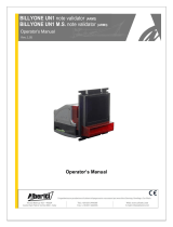
2.4 Component Overview
CBA9

User Manual CBA Range
<< Back to Contents
Copyright © Innovative Technology Ltd 2020 Doc: User Manual CBA Range
Version:2.1
Page 10 of 66
CBA11
2.5 Bezel Options
CBA Bezel fully compatible with NV9 range
ITL Part Number
Description
Details
PA00188
NV9USB Vertical Up Bezel (82mm)
http://innovative-
technology.com/shop/bezels/nv9-vertical-up-
bezel-detail
PA00189
NV9USB Standard Horizontal Bezel (82mm)
http://innovative-
technology.com/shop/bezels/nv9-standard-
horizontal-bezel-detail
PA00190
NV9USB Vertical Up Snout Bezel (82mm)
http://innovative-
technology.com/shop/bezels/nv9-vertical-up-
snout-bezel-detail
PA00191
NV9USB Vertical Down Snout Bezel (82mm)
http://innovative-
technology.com/shop/bezels/nv9-vertical-down-
snout-bezel-detail
PA00268
NV9USB Horizontal Bezel (69mm)
http://innovative-technology.com/shop/nv9-a-
nv11-spares/nv9-horizontal-69mm-width-bezel-
detail
PA00296
NV9USB Vertical Up/Down Flat Bezel
(66mm)
http://innovative-technology.com/shop/nv9-a-
nv11-spares/nv9-66mm-vertical-updown-flat-
bezel-detail
PA00323
NV9USB Vertical Up/Down Flat Bezel
(69mm)
http://innovative-technology.com/shop/nv9-a-
nv11-spares/nv9-69mm-width-vertical-updown-
flat-bezel-detail
PA00896
NV11 Standard Bezel
http://innovative-technology.com/shop/nv9-a-
nv11-spares/nv9-usb-rainbow-bezel-detail

User Manual CBA Range
<< Back to Contents
Copyright © Innovative Technology Ltd 2020 Doc: User Manual CBA Range
Version:2.1
Page 11 of 66
PA01144
NV9USB+ Rainbow Bezel (82mm)
http://innovative-
technology.com/shop/bezels/nv9-vertical-down-
snout-bezel-detail
PA00984
NV9USB Facia Short
http://innovative-technology.com/shop/nv9-a-
nv11-spares/nv9-usb-facia-short-detail
PA00985
NV9USB Facia Long
http://innovative-technology.com/shop/nv9-a-
nv11-spares/nv9-usb-facia-long-detail
2.6 Cashbox Options
CBA Cashbox fully compatible with NV9 range
ITL Part Number
Description
Details
PA00185
NV9 USB 300 Clip On Cashbox
http://www.innovative-
technology.com/shop/bezels/nv9-300-clip-on-
cashbox-detail
PA00186
NV9 USB 300 Lockable Cashbox
http://www.innovative-
technology.com/shop/bezels/nv9-300-lockable-
cashbox-detail
PA00192
NV9 USB 300 Slide Cashbox
http://www.innovative-
technology.com/shop/bezels/nv9-300-slide-
cashbox-detail
PA00193
NV9 600 Clip on Cashbox
http://innovative-technology.com/shop/nv9-a-
nv11-spares/nv9-600-clip-on-cashbox-detail
PA00194
NV9 600 Slide In Cashbox
http://innovative-technology.com/shop/nv9-a-
nv11-spares/nv9-600-slide-in-cashbox-detail
PA00898
NV11 Standard 300 Clip on Cashbox
http://innovative-technology.com/shop/nv9-a-
nv11-spares/nv11-standard-cashbox-detail

User Manual CBA Range
<< Back to Contents
Copyright © Innovative Technology Ltd 2020 Doc: User Manual CBA Range
Version:2.1
Page 12 of 66
3 MECHANICAL INSTALLATION
3.1 Compatibility
3.1.1 Hardware Compatibility
3.1.1.1 Machine Mounting
Assuming the suitable bezel (and cashbox) type has been ordered the CBA can be
used as fitting replacement for the following products:
• NV7
• NV7M
• NV9
• BV20
• BV100
• NV9 USB
The CBA may not be used as fitting replacement for the following products:
• NV150
• NV10 USB
• NV200
Please note: Considerations will need to be made when adding either the recycler
or printer module, as this will increase the space requirements inside the host
machine.
Innovative Technology Ltd. has a policy of continuous product improvement. Due to
design changes older model or product bezels (and cashboxes) may not be
compatible with the CBA. However, new product deliveries always include a bezel
(and cashbox) that must be used.
Caution!
Only use bezel (and cashbox)
delivered with the product!
3.1.1.2 Machine Interfacing
By design the CBA is pin to pin compatible with the suitable fitting replacement
products listed above. No changes to existing machine harnessing are required.

User Manual CBA Range
<< Back to Contents
Copyright © Innovative Technology Ltd 2020 Doc: User Manual CBA Range
Version:2.1
Page 13 of 66
3.1.1.3 Power Supply
It is vital that the CBA is connected to a power supply being able to provide the
required power environment. A weak power supply causes malfunctioning of the
CBA such like note rejects or missing credits. If the CBA is used as a fitting
replacement for an older model or product we recommend to check the power
supply specifications of the machine. The power supply of the machine might be
designed for the older model or product but not suitable for the CBA. The CBA might
have higher power consumption. Refer to 9.4 for full power requirement details of
the CBA.
Caution!
A weak power supply causes
malfunctioning!
3.1.2 Software Compatibility
3.1.2.1 Interface Protocols
When using the CBA as a fitting replacement for an older model or product some
events such like credits may be given earlier. This is due to improved firmware
routines and faster motors being used. This may cause missing events such like
credits in those host machines where timeouts are defined for the older model or
product. Please contact the machine manufacturer for full compatibility of the CBA.
Caution!
Timing issues may cause missing
events such like credits!
3.1.2.2 Re-programming
For re-programming the CBA always use the latest version of Validator Manager
available for download on our website. Older versions may not support the CBA. For
further details on Re-programming the CBA refer to 4.4.
Caution!
Older versions of Validator
Manager may not support the CBA!

User Manual CBA Range
<< Back to Contents
Copyright © Innovative Technology Ltd 2020 Doc: User Manual CBA Range
Version:2.1
Page 14 of 66
3.2 Bezel/Nozzle Mounting
3.2.1 Bezel/Nozzle Fitting
1. Locator lugs
Place bezel down
onto validator,
ensuring locating
lugs go into spaces
provided (1).
2. Lock bezel in place
Slide bezel
backwards until
you hear release
latch arm, click into
place.

User Manual CBA Range
<< Back to Contents
Copyright © Innovative Technology Ltd 2020 Doc: User Manual CBA Range
Version:2.1
Page 15 of 66
3.2.2 Bezel/Nozzle Removal
1. Release clips
Pull release clip
upwards (1)
With release clip held
upwards, you can
pull bezel towards
front of unit (2).
1. Lift Bezel
Now bezel is free of
locating lugs, lift
bezel upwards (3).

User Manual CBA Range
<< Back to Contents
Copyright © Innovative Technology Ltd 2020 Doc: User Manual CBA Range
Version:2.1
Page 16 of 66
3.3 Cashbox/Baseplate Mounting
Below you will find details on how to fit the different cashboxes mentioned in section
2.6.
Slide cashboxes are made up of 2 x parts. The outer housing and the cashbox itself,
which slides in and out of the housing. These are used for when the unit is mounted
horizontally.
Clip on cashboxes attach directly onto the validator. These are mainly used for when
the unit is mounted vertically.
3.3.1 Cashbox/Baseplate Fitting
1. Slide Cashbox
The outer housing has
2 x lugs on either side
and these need to be
pushed up into the
cashbox slots as per the
image.
Then slide housing
forwards to lock into
place.
The outer housing is
mounted inside the
machine and you simply
slide the removable
cashbox, inside the outer
housing.

User Manual CBA Range
<< Back to Contents
Copyright © Innovative Technology Ltd 2020 Doc: User Manual CBA Range
Version:2.1
Page 17 of 66
2. Clip-on Cashbox
The clip-on cashbox
attaches directly to the
validator and is identical
to the process above.
3.3.2 Cashbox Removal
1. Slide Cashbox
Remove the cashbox
from the outer
housing.
Pull cashbox release
catch away from
validator and slide
cashbox out.
Push the tab (1)
seen in the image
whilst sliding the
outer housing back,
so that the locating
tabs are free to
move away from the
validator.


User Manual CBA Range
<< Back to Contents
Copyright © Innovative Technology Ltd 2020 Doc: User Manual CBA Range
Version:2.1
Page 19 of 66
3.4 Lock Mounting
The CBA range has an option for a 300-lockable cashbox. This is designed for a 300-
slide cashbox option.
ITL Part Number: PA00186
Webshop link: https://innovative-technology.com/shop/nv9-a-nv11-spares/nv9-300-
lockable-cashbox-detail
Details on the locking position can be found below.
3.4.1 Lock Fitting
1. Screw Holes
The lockable door attaches
to the cashbox housing via
3 x screw holes, as shown.
These can be found on all
4 x sides of the cashbox.
Front Right; Front left Back
right; back let.
2. Locking Cam Slot
You’ll also see 4 x slots for
each position too. This is
where the lock slides into,
in order to lock the door in
place.
Please note: you want to
use the 3 x mounting
screw points, on the
opposite side of where
your lock will be.
For example: if you want the lock to be Front Right –
you’d mount the door on the front left. So that the door
swings round and locks on the side you specified.
3. Lock
Using front right as an
example, this specifies the
location of the lock (2).
In this case, the door is
mounted as seen (1).
Lock specification details
can be found below in
section 3.4.2.
/