4 Contents
Removing and Installing Drives . . . . . . . . . . . . . . . . . . . . . . . . . 28
Removing Drives from the Enclosure
. . . . . . . . . . . . . . . . . . . . 29
Installing SAS Drives in the Enclosure
. . . . . . . . . . . . . . . . . . . 30
Installing SATA Drives in the Enclosure
. . . . . . . . . . . . . . . . . . 32
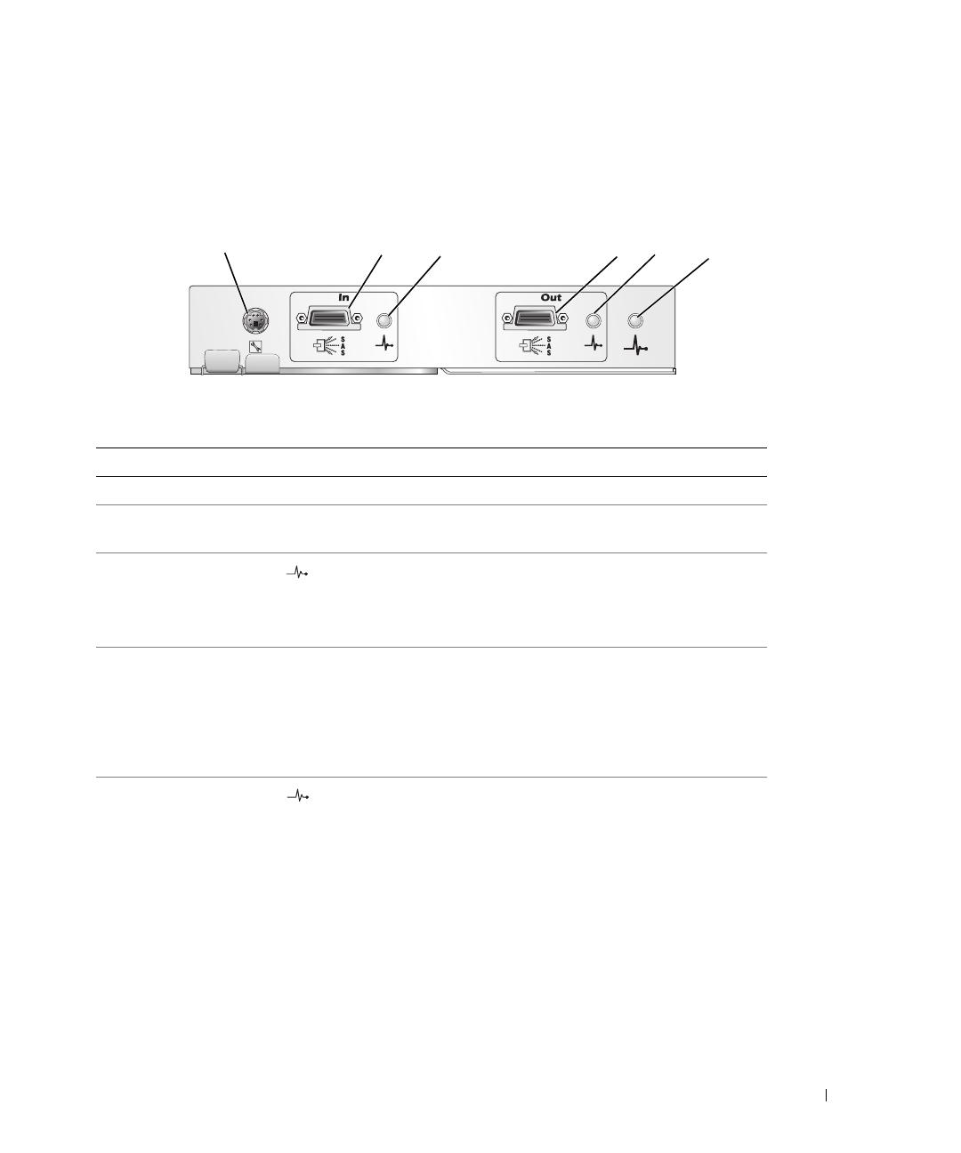
Removing and Installing an EMM
. . . . . . . . . . . . . . . . . . . . . . . . 34
Removing an EMM . . . . . . . . . . . . . . . . . . . . . . . . . . . . . 34
Installing an EMM. . . . . . . . . . . . . . . . . . . . . . . . . . . . . . 35
Installing an EMM Module Cover in an Empty Bay
. . . . . . . . . . . . . . . 36
Installing and Removing an EMM Module Cover
. . . . . . . . . . . . . . 36
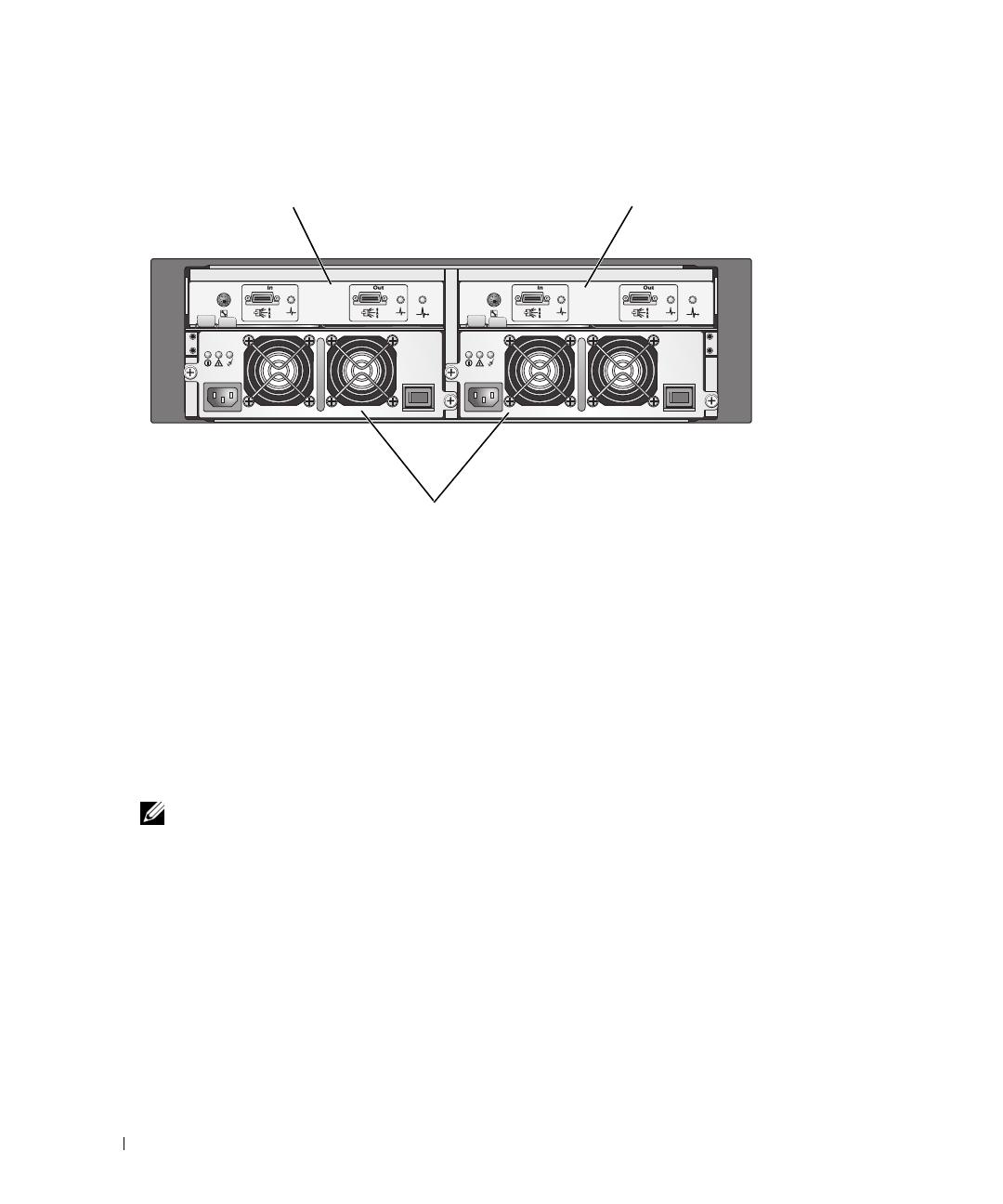
Removing and Installing the Power Supply/Cooling Fan Module
. . . . . . . 36
Removing a Power Supply/Cooling Fan Module
. . . . . . . . . . . . . . 37
Installing a Power Supply/Cooling Fan Module
. . . . . . . . . . . . . . 38
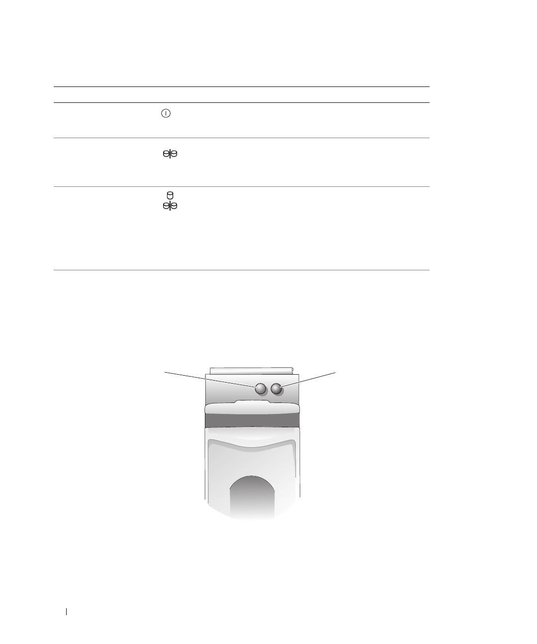
Removing and Installing the Control Panel
. . . . . . . . . . . . . . . . . . . 38
Removing the Control Panel
. . . . . . . . . . . . . . . . . . . . . . . . 38
Installing the Control Panel
. . . . . . . . . . . . . . . . . . . . . . . . . 39
Removing and Installing the Midplane
. . . . . . . . . . . . . . . . . . . . . 40
4 Troubleshooting Your Enclosure
Safety First—For You and Your Enclosure. . . . . . . . . . . . . . . . . . . . 43
Start-Up Routine
. . . . . . . . . . . . . . . . . . . . . . . . . . . . . . . . . 43
Troubleshooting a Loss of Communication Condition
. . . . . . . . . . . . . . 43
Troubleshooting External Connections
. . . . . . . . . . . . . . . . . . . . . 45
Troubleshooting a Wet Enclosure
. . . . . . . . . . . . . . . . . . . . . . . . 45
Troubleshooting a Damaged Enclosure
. . . . . . . . . . . . . . . . . . . . . 46
Troubleshooting Power Supplies
. . . . . . . . . . . . . . . . . . . . . . . . 46
Troubleshooting Enclosure Cooling Problems
. . . . . . . . . . . . . . . . . 47
Troubleshooting a Fan
. . . . . . . . . . . . . . . . . . . . . . . . . . . 48
Troubleshooting SAS and SATA Drives
. . . . . . . . . . . . . . . . . . . . . 48
Troubleshooting Enclosure Connections
. . . . . . . . . . . . . . . . . . . . 49