Page is loading ...

Operating Instructions
ARCUS SONIC
RTF 2.4 GHz
No. 2565

Operating instructions - ARCUS SONIC RTF 2.4 GHz No. 2565
2

Contents Page
Explanation of specialist terms / Contents 3
Safety Notes 4, 5
Set contents / Specification / Recommended accessories 6
Assembling the model 7
Charging the flight battery / LiPo battery safety notes 8
Summary of transmitter settings in Mode 1 und Mode 2 9
Primary and expanded control functions / converting the transmitter 10
Transmitter settings in Mode 1 11
Transmitter settings in Mode 2 12
Flight preparation 13
Controlling the model 14
Important notes 15
Re-binding the transmitter 16
Protective function of the BL speed controller 17
Setup menu 17
Airbrake setting 17
Replacement parts list 18
General notes 19
Explanation of specialist terms:
Motor speed ("Throttle"): This controls the rotati-
onal speed of the motor. Stick forward = maximum
speed; stick back = motor off.
Rudder: This controls the model's attitude around
the vertical (yaw) axis, causing the aeroplane to fly
to the right or left.
Up-elevator / down-elevator: This controls the
model's flight attitude around the lateral (pitch)
axis. Stick forward = the model descends; stick
back = the model climbs.
Ailerons: This controls the model's flight attitude
around the longitudinal (roll) axis. Stick right = right
wing down; stick left = left wing down.
Mode 1: Function assignment of the control move-
ments relative to the stick movements.
In this case throttle and ailerons are controlled by
the right-hand transmitter stick, elevator and rudder
by the left-hand stick.
Mode 2: Function assignment of the control move-
ments relative to the stick movements.
In this case throttle and rudder are controlled by
the left-hand transmitter stick, elevator and ailerons
by the right-hand stick.
Dual-Rates:
Switchable travel reduction for control movements
3
Operating instructions - ARCUS SONIC RTF 2.4 GHz No. 2565

Be sure to read these Safety Notes before you assemble your mo-
del. Always keep to the procedures and settings recommended in
the instructions.
If you are operating a radio-controlled model aircraft, helicopter, car
or boat for the first time, we recommend that you enlist the aid of an
experienced modeller to help you.
Safety Notes
Radio-controlled models are not toys in the usual sense of the term.
Young persons under fourteen years should only be allowed to operate
them under the supervision of an adult.
Building and operating these models requires technical expertise, manu-
al skills, a careful attitude and safety-conscious behaviour.
Errors, negligence and omissions in building or flying these models can
result in serious personal injury and damage to property.
Since the manufacturer and vendor are not in a position to check that
your models are built and operated correctly, all we can do is bring these
hazards expressly to your attention. We deny all further liability.
Aircraft propellers, and all moving parts generally, consti-
tute a constant injury hazard.
It is essential to avoid touching such parts.
Bear in mind that motors and speed controllers may be-
come hot when operating.
It is essential to avoid touching such parts.
Do not stand close to the hazard area around rotating parts when
an electric motor is connected to the flight battery.
You must take care to keep all other objects away from moving
or rotating parts!
Observe the instructions provided by the battery manufac-
turer.
Overcharged or incorrectly charged batteries may explode. Take
care to maintain correct polarity.
Ensure the equipment is protected from dust, dirt and moisture conta-
mination. Do not subject the system to excessive heat, cold or vibration.
Use the recommended charger only, and avoid charging the batteries for
longer than the prescribed period.
Check your equipment for damage at regular intervals, and replace de-
fective components with genuine spare parts.
Do not re-use any devices which have been damaged in a crash or by
water, even when they have dried out again.
Send the equipment to the robbe Service Department for checking, or
replace the parts in question.
Crash or water damage can result in concealed defects which may lead
to failure in subsequent use.
Use only those components and accessories which we specifically re-
commend.
4
Operating instructions - ARCUS SONIC RTF 2.4 GHz No. 2565

Do not carry out modifications to the radio control system components
apart from those described in the instructions.
Operating the model
•Neveryoverortowardsspectatorsorotherpilots,andmaintainasafe
distance from them at all times.
•Neverendangerpeopleoranimals.
•Neveryclosetohigh-tensionoverheadcablesorresidentialareas.
•Donotoperateyourmodelinthevicinityofcanallocksoropenwater-
ways.
•Do notoperate yourmodel from public roads, motorways,paths and
squares etc.; use authorised model flying sites only.
• Never operate the model in stormy weather.
Never “point” the transmitter aerial straight at the model when operating
it. The transmitter signal is at its weakest in this direction. It is always best
to stand with the long side of the aerial angled towards the model.
Insurance
Ground-based models are usually covered by standard personal third-
party insurance policies. In order to fly model aircraft you will need to
extend the cover of your existing policy, or take out specific insurance.
Check your insurance policy and take out new cover where neces-
sary.
Liability Exclusion
robbe Modellsport is unable to ensure that you observe the assembly and
operating instructions, or the conditions and methods used for installing,
operating and maintaining the model components.
For this reason we accept no liability for loss, damage or costs which are
due to the erroneous use and operation of our products, or are connected
with such operation in any way.
Regardless of the legal argument employed, our obligation to pay com-
pensation is limited to the invoice value of those robbe products directly
involved in the event in which the damage occurred, unless otherwise
prescribed by law. This does not apply if the company is deemed to have
unlimited liability according to statutory regulation due to deliberate or
gross negligence.
5
Operating instructions - ARCUS SONIC RTF 2.4 GHz No. 2565

Dear customer,
Congratulations on choosing a model aircraft from our ran-
ge. Many thanks for placing your trust in us.
The model can be completed and made ready to fly very
quickly. Please read right through these instructions before
attempting to fly the model for the first time, as this will
make it much easier to operate the model safely.
All directions, such as “right-hand”, are as seen from the
tail of the model, looking forward.
Specification:
Wingspan: 2000 mm
Overall length: 1200 mm
All-up weight: approx. 970 g
Motor: 28-35 BL motor
Power supply: LiPo battery, 11.1 V / 1800 mAh
Recommended accessories:
8 x 8005 NiMH AA-size cell, 1.2 V / 2500 mAh
1 x F1415 Transmitter charge lead
1 x POWER PEAK® Uni 7 EQ 230 V
Set contents:
1 x ARCUS SONIC RTF 2.4 GHz
1 x Wing joiner spar
1 x 2.4 GHz transmitter
1 x Tailplane retaining screw
2 x Wing retaining pin
1 x Battery charge lead
1 x Lithium-Ion-Polymer battery
1 x Charger for Lithium-Ion-Polymer battery
Please be sure to observe the safety notes regar-
ding the safe handling of Lithium-Ion-Polymer
batteries on page 8.
6
Operating instructions - ARCUS SONIC RTF 2.4 GHz No. 2565

7
Assembling the model
Fit the tailplane into the
slot in the fin from the
left-hand side using only
moderate pressure, until
it is positioned flush with
the fuselage (Fig. 1).
Set the tailplane at right-
angles to the fuselage
centreline.
Check that the tailplane
is located correctly, then
fit the screw supplied to
secure it (Fig. 2).
Connect the pushrod to
the elevator horn (Fig. 3).
Slide the wing joiner spar into the right-hand wing panel
with the machined groove located on the underside (Fig.4).
When the groove in the spar lines up with the opening in
the underside of the wing, insert a retaining pin (Fig. 5) to
secure the spar.
Connect the aileron servo (green mark on plug and socket)
(Fig. 6) before inserting the right wing (with the secured
joiner spar) into the recess in the fuselage. Now slide the
wing into the fuselage as far as it will go (Fig. 7). Slide the
left wing panel onto the projecting joiner spar, and connect
the aileron servo (red mark on plug and socket). Push the
wing into the fuselage recess as far as it will go. Check that
both wings are located correctly, then insert the second
retaining pin.
Fig. 4
Fig. 6
Fig. 5
Fig. 7
Operating instructions - ARCUS SONIC RTF 2.4 GHz No. 2565
Fig. 1
Fig. 2
Fig. 3

Using the charger to charge the flight battery
The battery charger must be connected to a 12 V power
source with a minimum output power of 2 A using the con-
necting lead supplied. Correct polarity is essential.
The red monitor LED on the charger lights up. Connect the
battery to the charger.
During the charge process the green monitor LED on the
charger flashes. When the charge process is complete,
you will hear an audible signal, and the green monitor LED
on the charger glows constantly.
Disconnect the battery from the charger as soon as it is
fully charged, and disconnect the power source from the
power supply.
Safety Notes
Do not operate your charger and batteries on an inflam-
mable surface, and do not leave the equipment running
unsupervised. Protect from damp. Do not subject to direct
sunshine, and do not cover the charger.
Do not charge batteries that are hot to the touch. Allow
batteries to cool down to ambient temperature. Charge the
battery only using the charger included in the set; do not
use any other charger. The charger should only be used to
charge the battery included in the set.
8
Safety Notes regarding LiPo batteries:
•Donotplacethebatteryinwateroranyotherliquid.
•Donotheatorincineratethebattery;donotplaceit
in a microwave oven.
•Avoidshort-circuits,andneverchargethebatterywith
reversed polarity
•Donotsubjectthebatterytopressureorshockloads,and
never distort or throw the pack.
•Neversolderdirectlytothebattery
•Donotmodifyoropenthebattery
•Batteriesmustonlybechargedwithasuitablecharger;
never connect the battery directly to a mains power supply.
•Neverchargeordischargeabatteryinbright
sunlight, or close to a heater or open fire.
•Donotusethebatteryinareassubjectto
high levels of static discharge.
•Anyoftheseerrorscanresultindamagetothebattery,
explosion or even fire.
•Keepthebatteryoutofthereachofchildren
•Donotallowescapedelectrolytetocomeintocontact
with fire, as it is highly inflammable, and may ignite.
•Avoidtheuidelectrolytecontactingtheeyes.
If this should happen, flush with copious amounts of clean
water and contact a doctor without delay.
•Theuidelectrolytecanalsoberemovedfromclothing
and other objects by rinsing in plenty of water.
LIABILITY EXCLUSION
Since robbe Modellsport is not in a position to monitor the
handling of these batteries, we expressly deny all liability and
guarantee claims where the batteries have been incorrectly
charged, discharged or handled.
Operating instructions - ARCUS SONIC RTF 2.4 GHz No. 2565

9
Operating instructions - ARCUS SONIC RTF 2.4 GHz No. 2565
Status indicator
Airbrakes
Status indicator
Airbrakes
Status indicator
Throttle
control
Elevator
trim display
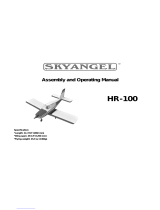
Transmitter settings, Mode 1: Transmitter settings, Mode 2 (as supplied):
Elevator
control and
Rudder
control
Elevator trim
Switch
Airbrakes
Switch
Airbrakes
Rudder
trim
Rudder
trim
Aileron
trim
Aileron
trim
Throttle
control
and
Aileron
control
Throttle trim
Select switch
Dual Rate
Select switch
Dual Rate
Aileron
control and
Elevator
control
Throttle
control and
Rudder
control
Elevator trimThrottle trim
Elevator
trim display
Status indicator
Throttle control
Dual-Rate status indicator Dual-Rate status indicator
Also: Status indicator for the individual trim settings Also: Status indicator for the individual trim settings
Status indicator, mode select
Status indicator, mode select
Rudder
trim display
Rudder
trim display
Aileron trim display Aileron trim display
Status indicator, transmitter
battery
Status indicator, transmitter
battery
Status indicator
Rotational speed
Status indicator
Rotational
speed
(Complete operating instructions for the J5 transmitter can be found in the Download area at www.robbe.com)

10
"Primary" and "expanded" control function setting
The transmitter offers the facility to adjust the sensitivity
of the stick movements. We recommend "softer" reduced
travels for beginners.
Open the transmitter battery compartment and insert the
eight fully-charged NiMH cells (check for correct polarity).
Switching sensitivity:
Switch the transmitter on.
Reduced control function:
Locate the toggle switch at top
right of the transmitter, and move it
down. The "Status indicator, Dual
Rate" disc is reduced to half.
Enlarged control function:
Locate the toggle switch at top
right of the transmitter, and move
it up. The "Status indicator, Dual
Rate" disc is shown in full.
Converting the transmitter from "Mode 2" (throttle
left) to "Mode 1" (throttle right)
The transmitter is supplied set to Mode 2 as standard. If
you prefer Mode 1 and wish to convert the transmitter to
that mode, use this procedure:
The transmitter must be switched off.
Locate the central cover over the battery compartment in
the rear of the transmitter, and open it by pressing both
retaining clips together using two fingers. Lift the cover up
and off.
The toggle switches located under the cover are used to
select Mode 1 and Mode 2:
Toggle switch up = Mode 1
Toggle switch down = Mode 2
You can now close the battery cover and switch the trans-
mitter on. The screen displays the new setting.
Status indicator, mode select
Dual-Rate status indicator
(see left)
Operating instructions - ARCUS SONIC RTF 2.4 GHz No. 2565

11
Transmitter settings Mode 1
Throttle trim:
If the propeller starts to move without
you touching the throttle stick, or does
not respond to stick movements, cor-
rect this with the throttle trim.
Rudder trim:
If the model's nose turns to right or left
when launched, adjust the rudder trim
buttons until the model maintains a
constant heading.
Elevator trim:
If the model raises or lowers its nose
when launched, adjust the elevator
trim until the model maintains a stable
attitude.
Aileron trim:
If the model rolls to right or left when
launched, adjust the aileron trim
buttons until the model maintains a
constant heading.
a
a
a
a
a
a
a
a
a
a
a
a
a
a
a
a
Operating instructions - ARCUS SONIC RTF 2.4 GHz No. 2565

12
Transmitter settings, Mode 2
Throttle trim:
If the propeller starts to move without
you touching the throttle stick, or does
not respond to stick movements, cor-
rect this with the throttle trim.
Rudder trim:
If the model's nose turns to right or left
when launched, adjust the rudder trim
buttons until the model maintains a
constant heading.
Elevator trim:
If the model raises or lowers its nose
when launched, adjust the elevator
trim until the model maintains a stable
attitude.
Aileron trim:
If the model rolls to right or left when
launched, adjust the aileron trim
buttons until the model maintains a
constant heading.
a
a
a
a
a
a
a
a
a
a
a
a
a
a
a
a
Operating instructions - ARCUS SONIC RTF 2.4 GHz No. 2565

13
Flight preparation
Switch the transmitter on (Fig. 1).The battery status is
displayed at the top of the screen. Move the throttle stick
and trim to the lowest position. Open the canopy, place
the fully charged LiPo flight battery in the recess, and use
the Velcro tape to hold it in place. The Centre of Gravity
(see illustration on page 15) is checked by supporting the
model under the wings on both sides of the fuselage using
your index fingers, and allowing it to hang freely. Ideally
the model will now balance level, with the nose inclined
slightly down. The CG can be fine-tuned by adjusting the
battery position.
Now connect the battery and replace the canopy on the
fuselage (Figs. 2 - 4).
The transmitter and the receiver are now ready for use.
Repeat this procedure every time you wish to fly the
model.
Note: the 2.4 GHz transmitter and receiver are supplied
already bound at the factory. It will only be necessary to
bind the system again after a repair, or if you replace a
component.
The correct pre-flight procedure.
Fig. 1 Fig. 2 Fig. 3
Fig. 4
Checking the working systems
Before the first flight it is important to set all the trims - ex-
cept for the throttle trim - to centre. The throttle stick must
be in the "fully back" position (towards you). If the propeller
turns, adjust the throttle trim until it comes to a halt.
The correct post-flight procedure.
Open the canopy and remove the flight battery. Replace
the canopy on the model, then switch the transmitter off.
Preparations for the first flight:
Wait for a day with absolute flat calm
conditions.
Charge the flight battery before
flying.
Operating instructions - ARCUS SONIC RTF 2.4 GHz No. 2565

14
Controlling the model in Mode 1 Controlling the model in Mode 2
Operating instructions - ARCUS SONIC RTF 2.4 GHz No. 2565
High RPM (launch):
Left turn:
Descent:
Roll right:
Airbrakes retracted:
High RPM (launch):
Left turn:
Descent:
Roll right:
Airbrakes retracted:
Motor off (landing):
Right turn:
Climb:
Roll left:
Airbrakes extended:
Motor off (landing):
Right turn:
Climb:
Roll left:
Airbrakes extended:

15
Once the model is properly trimmed, you can practise the
art of flying, and carry out manoeuvres such as circles,
squares, rectangles and figures-of-eight.
To avoid giving incorrect control commands, always stand
behind and to one side of the model.
You can fly a square pattern by alternating the direction
of flight: away from the pilot, to the pilot's right, and then
towards the pilot.
Tip: when the model is flying with the nose pointing
towards you, the controls are reversed (apart from
elevator and throttle control).
Important Notes
Launching: Hold the model in your hand, set the motor to full power, and
push the model forward smartly, directly into any wind. It is essential to
adjust the trims so that the aeroplane flies in a stable attitude, climbing
smoothly. Use the controls gently at first to learn how the model responds
to flight commands.
Landing: Slowly and steadily reduce the throttle setting until the mo-
del descends and touches down. The ailerons can be used as airbrakes
using the left switch on the transmitter; this helps to reduce wing lift; at
the same time the aileron function is still available. Once the model has
landed, disconnect the flight battery from the receiver, and finally switch
the transmitter off.
Caution: Stopping (obstructing) the motor when it is turning can cause
serious damage to the mechanical system, and may even result in a fire.
If the propeller is forcibly stopped, immediately move the throttle stick
back to Idle!
Note re. the flight battery: As soon as you notice a reduction in motor
power, land immediately and disconnect the battery. Never continue
flying until the battery is flat, as this causes a deep-discharge condition,
which results in permanent damage. Allow the battery to cool down
before recharging it.
Replacing the propeller:
A damaged propeller must be replaced immediately.
The first few flights
Operating instructions - ARCUS SONIC RTF 2.4 GHz No. 2565

Fig. 1
16
Operating instructions - ARCUS SONIC RTF 2.4 GHz No. 2565
Re-binding the transmitter
This procedure is only necessary if individual components are replaced.
Move the throttle stick and trim to the bottom position (motor stopped), then
place the transmitter as close as possible to the receiver.
Locate the horizontal trim switch below the right-hand stick unit on the transmit-
ter, and push it to the left while you switch the transmitter on (Fig. 1). The screen
now displays the message "5-H", and emits a series of beeps. Connect the LiPo
flight battery, and the LED on the receiver flashes at a high rate. Now hold the
Easy Link button pressed in for three to five seconds until the LED goes out.
When the binding process is complete, the transmitter's screen reverts to nor-
mal mode, and the LED on the receiver glows constantly. The servos will now
respond normally to stick movements.
Checking the working systems
Before the first flight it is important to set all the trims - except for the throttle trim
- to centre. The throttle stick must be in the "fully back" position (towards you). If
the propeller turns, adjust the throttle trim until it comes to a halt.

17
Protective function of the BL speed controller with the
battery connected:
If the flight battery is connected to the Arcus-Sonic's BL con-
troller, and the motor is not operated for a period of 2.5 mi-
nutes, a clear audible warning is emitted by the model. This
protective function is intended to remind the pilot to discon-
nect the battery from the controller after every flight.
If the model is allowed to glide for a long period without the
motor being switched on, this will trigger the audible warning.
You can switch it off again by "opening the throttle" once (in
which case the motor will not start running). The audible war-
ning has no effect on the servo functions or the receiver's
performance.
Airbrake setting
In the default setting the airbrakes (ailerons) extend down-
ward. This is the procedure for reversing this setting (ailerons
up):
Push the "MENU" button (right-hand trim lever) to the right
three times: "F-P" flashes. Now press the "ENTER" button
(left-hand trim lever): the current setting flashes.
One switch position is used for the neutral position of the ai-
lerons, which should be 50%. The other switch position de-
termines the travel of the airbrake function: if you set a value
above 50, the airbrakes (ailerons) extend up; if you set a va-
lue below 50, the brakes extend down.
Press "ENTER" to store the selected value, then quit the Se-
tup menu with "EXIT".
Data recovery
button
Adjuster
button
Exit Enter
Menu button
Setup menu
Enter the menu program by
pressing both trim levers down,
as shown in the illustration (Fig.
1), then switch the transmitter
on: the displays "NOR", "REV"
and the channel line flash.
In the "Setup menu" the func-
tions of the trim buttons are as
shown in Fig. 2.
Operating instructions - ARCUS SONIC RTF 2.4 GHz No. 2565
Fig. 1
Fig. 2

18
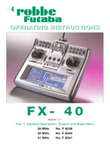
Replacement parts list - ARCUS SONIC RTF
Order No. Description
25650001 Fuselage
25650002 Tail set
25650003 Wing
25650004 Propeller set
25650005 Decal sheet (not shown)
NE200105 Control surface horns
NE200106 Control surface linkage
NE200107 Screw set
NE200108 Propeller driver
NE200109 LiPo battery, 11.1 V / 1800 mAh
NE200110 Motor set
NE200111 Servo extension lead
NE200112 Y-lead
NE200113 Battery charger
NE200114 Servo, 9 g, length: 170 mm
NE200115 Servo, 9 g, length: 450 mm
NE200116 BL speed controller, 20 A
NE200117 Receiver set
NE200118 Canopy (not shown)
NE200119 Retaining clip (not shown)
25650001 NE200105
NE200109
NE200113
25650002 NE200106
NE200110
NE200114
25650003
NE200107
NE200111
NE200115
2565004
NE200108
NE200112
NE200116 NE200117
Operating instructions - ARCUS SONIC RTF 2.4 GHz No. 2565

19
This symbol means that you should dispose of electrical and electronic equipment separately from the household waste when it reaches
the end of its useful life. Take your unwanted equipment to your local council collection point or recycling centre. This requirement applies to
member countries of the European Union as well as other non-European countries with a separate waste collection system.
Disposal of batteries
Batteries must not be discarded as domestic refuse. To protect the environment, always return exhausted or defective cells to your local recy-
cling centre. These include retail sales outlets for batteries, and communal toxic waste disposal centres. Cover any bare wires with insulating
tape in order to avoid short-circuits.
robbe Modellsport GmbH & Co. KG hereby declares that this device conforms to the fundamental requirements and other relevant
regulations of the appropriate CE Directive. Under www.robbe.com, you will find the original Conformity Declaration by clicking on the Logo
button "Conform" shown together with the appropriate device description.
Operating instructions - ARCUS SONIC RTF 2.4 GHz No. 2565

robbe Modellsport GmbH & Co.KG
Metzloserstraße 38 · D-36355 Grebenhain
Technical hotline: +49 (0)66 44 / 87-777 · hotline@robbe.com
Commercial register: Gießen Regional Court HRA 2722
Partner with personal liability:
robbe Modellsport Beteiligungs GmbH Gießen / HRB 5793 · Managing Directors: G. Geiger, E. Dörr
Errors and technical modifications reserved. · Copyright robbe-Modellsport 2011
Duplication and copying of the text, in whole or in part, is only permitted with the prior written approval of robbe-Modellsport GmbH & Co. KG
20
Operating instructions - ARCUS SONIC RTF 2.4 GHz No. 2565
/