Page is loading ...

Hoshizaki
“A Superior Degree
of Reliability”
www.hoshizaki.com
Models
F-450MAH(-C)
Modular Flaker
Hoshizaki America, Inc.
SERVICE MANUAL
Issued: 8-25-2009

2
IMPORTANT
Only qualified service technicians should install, service, and maintain the
icemaker. No service or maintenance should be undertaken until the technician
has thoroughly read this Service Manual. Failure to service and maintain the
equipment in accordance with this manual may adversely affect safety,
performance, component life, and warranty coverage.
Hoshizaki provides this manual primarily to assist qualified service technicians in the
service and maintenance of the icemaker.
Should the reader have any questions or concerns which have not been satisfactorily
addressed, please call, write, or send an e-mail message to the Hoshizaki Technical
Support Department for assistance.
HOSHIZAKI AMERICA, INC.
618 Highway 74 South
Peachtree City, GA 30269
Attn: Hoshizaki Technical Support Department
Phone: 1-800-233-1940 Technical Support
(770) 487-2331
Fax: 1-800-843-1056
(770) 487-3360
E-mail: [email protected]
Web Site: www.hoshizaki.com
NOTE: To expedite assistance, all correspondence/communication MUST include the
following information:
• Model Number
• Serial Number
• Complete and detailed explanation of the problem.

3
CONTENTS
I. Specifications .................................................................................................................... 4
1. F-450MAH .................................................................................................................... 4
2. F-450MAH-C ................................................................................................................ 5
II. General Information .......................................................................................................... 6
1. Construction .................................................................................................................6
2. Control Box Layout ....................................................................................................... 7
3. Timer Board ..................................................................................................................8
[a] Solid-State Control ................................................................................................ 8
[b] Timer Board ........................................................................................................... 8
[c] Sequence .............................................................................................................. 9
III. Technical Information ..................................................................................................... 12
1. Water Circuit and Refrigeration Circuit........................................................................ 12
2. Wiring Diagram ........................................................................................................... 13
[a] F-450MAH ........................................................................................................... 13
[b] F-450MAH-C ....................................................................................................... 14
3. Sequence of Electrical Circuit .................................................................................... 15
4. Timing Chart ............................................................................................................... 25
5. Performance Data ....................................................................................................... 28
[a] F-450MAH ........................................................................................................... 28
[b] F-450MAH-C ....................................................................................................... 29
IV. Service Diagnosis.......................................................................................................... 30
1. No Ice Production ....................................................................................................... 30
2. Low Ice Production ..................................................................................................... 33
3. Other ........................................................................................................................... 34
V. Removal and Replacement of Components ................................................................... 35
1. Service for Refrigerant Lines ...................................................................................... 35
[a] Refrigerant Recovery........................................................................................... 35
[b] Evacuation and Recharge [R-404A] .................................................................... 35
2. Brazing ....................................................................................................................... 36
3. Removal and Replacement of Compressor ................................................................ 37
4. Removal and Replacement of Drier ........................................................................... 38
5. Removal and Replacement of Expansion Valve ......................................................... 39
6. Removal and Replacement of Evaporator Assembly ................................................ 40
7. Removal and Replacement of Fan Motor ................................................................... 42
8. Removal and Replacement of Control Water Valve .................................................... 42
9. Removal and Replacement of Flush Water Valve ....................................................... 43
VI. Cleaning and Maintenance ........................................................................................... 44
1. Preparing the Icemaker for Long Storage ................................................................... 44
2. Cleaning and Sanitizing Instructions .......................................................................... 45
[a] Cleaning Solution ................................................................................................ 45
[b] Cleaning Procedure ............................................................................................ 46
[c] Sanitizing Solution............................................................................................... 47
[d] Sanitizing Procedure - Initial................................................................................ 47
[e] Sanitizing Procedure - Final ................................................................................ 48
3. Maintenance Instructions ............................................................................................ 50
Please review this manual. It should be read carefully before the icemaker is serviced or
maintenance operations are performed. Only qualified service technicians should service and
maintain the icemaker. This manual should be made available to the technician prior to service
or maintenance.

4
AC SUPPLY VOLTAGE 115/60/1
COMPRESSOR 120 V 8.5 RLA 51 LRA
GEAR MOTOR 120 V 1.6 FLA 1/6 HP
FAN MOTOR 115 V 0.85FLA 50W
OTHER 120 V 0.03A
MAXIMUM FUSE SIZE 20 A
MAX. HACR BREAKER (USA ONLY) 20 A
MAX. CIRC. BREAKER (CANADA ONLY) 20 A
MINIMUM CIRCUIT AMPACITY 20 A
APPROXIMATE ICE PRODUCTION Ambient WATER TEMP. (°F)
PER 24 HR. Temp.(°F) 50 70 90
lbs./day ( kg/day ) 70 *476 (216) 456 (207) 435 (197)
Reference without *marks 80 416 (189) 397 (180) 379 (172)
90 362 (164) *355 (161) 330 (150)
100 315 (143) 301 (137) *282 (128)
SHAPE OF ICE Flake
ICE QUALITY Approx. 70%, Ice (90/70°F, Conductivity 200 µs/cm)
APPROXIMATE STORAGE CAPACITY N/A
ELECTRIC & WATER CONSUMPTION 90/70°F 70/50°F
ELECTRIC W (kWH/100 lbs.) 915 (6.2) 858 (4.3)
POTABLE WATER 43 (12) 57 (12)
gal./24HR (gal./100 lbs.)
EXTERIOR DIMENSIONS (WxDxH) 21"-7/8" x 27-3/8" x 21-61/64" (556 x 696 x 557.7mm)
EXTERIOR FINISH Stainless Steel, Galvanized Steel (Rear)
WEIGHT Net 150 lbs. ( 68 kg ), Shipping 175 lbs. ( 80 kg )
CONNECTIONS - ELECTRIC Permanent - Connection
- WATER SUPPLY Inlet 1/2" FPT
- DRAIN Outlet 3/4" FPT
ICE MAKING SYSTEM Auger type
HARVESTING SYSTEM Direct Driven Auger ( 1/6 HP Gear Motor )
ICE MAKING WATER CONTROL Float Switch
COOLING WATER CONTROL N/A
BIN CONTROL SYSTEM Mechanical Bin Control ( Proximity Sw. )
COMPRESSOR Hermetic, Model RS43C1E-CAA-219
CONDENSER Air-cooled, Fin and tube type
EVAPORATOR Copper Tube on Cylinder
REFRIGERANT CONTROL Thermostatic Expansion Valve
REFRIGERANT CHARGE R-404A, 1 lb. (455 g)
DESIGN PRESSURE High 427 PSIG, Low 230 PSIG
P.C. BOARD CIRCUIT PROTECTION High Voltage Cut-off Relay
COMPRESSOR PROTECTION Internal Protector
GEAR MOTOR PROTECTION Manual reset Circuit Breaker or Fuse
REFRIGERANT CIRCUIT PROTECTION Auto-reset High Pressure Control Switch
LOW WATER PROTECTION Float Switch and Timer
ACCESSORIES - REQUIRED Ice Storage Bin
OPERATING CONDITIONS VOLTAGE RANGE 104 - 127 V
AMBIENT TEMP. 45 - 100° F
WATER SUPPLY TEMP. 45 - 90° F
WATER SUPPLY PRESSURE 10 - 113 PSIG
I. Specifications
1. F-450MAH
We reserve the right to make changes in specifications and design without prior notice.

5
AC SUPPLY VOLTAGE 115/60/1
COMPRESSOR 120 V 8.5 RLA 51 LRA
GEAR MOTOR 120 V 1.6 FLA 1/6 HP
FAN MOTOR 115 V 0.85FLA 50W
OTHER 120 V 0.03A
MAXIMUM FUSE SIZE 20 A
MAX. HACR BREAKER (USA ONLY) 20 A
MAX. CIRC. BREAKER (CANADA ONLY) 20 A
MINIMUM CIRCUIT AMPACITY 20 A
APPROXIMATE ICE PRODUCTION Ambient WATER TEMP. (°F)
PER 24 HR. Temp.(°F) 50 70 90
lbs./day ( kg/day ) 70 *426 (193) 407 (185) 387 (176)
Reference without *marks 80 368 (167) 350 (159) 333 (151)
90 317 (144) *310 (141) 287 (130)
100 273 (124) 260 (118) *244 (111)
SHAPE OF ICE Cubelet
ICE QUALITY Approx. 80%, Ice (90/70°F, Conductivity 200 µs/cm)
APPROXIMATE STORAGE CAPACITY N/A
ELECTRIC & WATER CONSUMPTION 90/70°F 70/50°F
ELECTRIC W (kWH/100 lbs.) 956 (7.4) 880 (5.0)
POTABLE WATER 37 (12) 51 (12)
gal./24HR (gal./100 lbs.)
EXTERIOR DIMENSIONS (WxDxH) 21"-7/8" x 27-3/8" x 21-61/64" (556 x 696 x 557.7mm)
EXTERIOR FINISH Stainless Steel, Galvanized Steel (Rear)
WEIGHT Net 150 lbs. ( 68 kg ), Shipping 175 lbs. ( 80 kg )
CONNECTIONS - ELECTRIC Permanent - Connection
- WATER SUPPLY Inlet 1/2" FPT
- DRAIN Outlet 3/4" FPT
ICE MAKING SYSTEM Auger type
HARVESTING SYSTEM Direct Driven Auger ( 1/6 HP Gear Motor )
ICE MAKING WATER CONTROL Float Switch
COOLING WATER CONTROL N/A
BIN CONTROL SYSTEM Infrared Sensor
COMPRESSOR Hermetic, Model RS43C1E-CAA-219
CONDENSER Air-cooled, Fin and tube type
EVAPORATOR Copper Tube on Cylinder
REFRIGERANT CONTROL Thermostatic Expansion Valve
REFRIGERANT CHARGE R-404A, 1 lb. (455 g)
DESIGN PRESSURE High 427 PSIG, Low 230 PSIG
P.C. BOARD CIRCUIT PROTECTION High Voltage Cut-off Relay
COMPRESSOR PROTECTION Internal Protector
GEAR MOTOR PROTECTION Manual reset Circuit Breaker or Fuse
REFRIGERANT CIRCUIT PROTECTION Auto-reset High Pressure Control Switch
LOW WATER PROTECTION Float Switch and Timer
ACCESSORIES - REQUIRED Ice Storage Bin
OPERATING CONDITIONS VOLTAGE RANGE 104 - 127 V
AMBIENT TEMP. 45 - 100° F
WATER SUPPLY TEMP. 45 - 90° F
WATER SUPPLY PRESSURE 10 - 113 PSIG
2. F-450MAH-C
We reserve the right to make changes in specifications and design without prior notice.

6
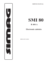
II. General Information
1. Construction
Water Supply
Inlet
Junction Box
Condenser
Fan Motor
Compressor
Drier
Control Water Valve
Bin Control
Ice Chute
Evaporator
Flush Water
Valve
Control Box
Gear Motor

7
2. Control Box Layout
Note: The above component names are identical with the wiring label, but not with
the parts list.

8
3. Timer Board
[a] Solid-State Control
1) A HOSHIZAKI exclusive solid-state control is employed in the self-contained flaker
icemakers.
2) A printed circuit board (hereafter called “timer board”) includes a stable and high
quality control system.
3) All models are pre-tested and factory-adjusted.
[b] Timer Board
CAUTION
1. Fragile, handle very carefully.
2. A timer board contains CMOS (Complementary Metal-Oxide Semicon-
ductor) integrated circuits, which are susceptible to failure due to static
discharge. It is especially important to use an anti-static wrist strap when
handling or replacing the board.
3. Do not touch the electronic devices on the board or the back of the
board to prevent damage to the board.
4. Do not change wiring and connections. Especially, never misconnect
terminals.
5. Do not fix the electronic devices or parts on the board in the field. Always
replace the whole board assembly when it goes bad.
The icemaker is controlled by the timer board for the following purposes:
1) To prevent the gear motor and the compressor from starting or stopping
simultaneously.
2) To reduce remaining ice in the refrigeration casing.
3) To protect the unit in case of low water and low water pressure.
4) To protect the unit in case the bin control causes chattering.

9
Fig. 1
[c] Sequence
Fig. 2

10
Fig. 3
EDOCTRAP10-503734
LEDOM10C441AA2H
GNITARzH06/05CAV42
1T.ces51±06
2T.ces22±09
3T.ces54±051
4Tsselro.ces1
5T%07±.ces7.6
6T%07±.ces7.6

11
Functions of Terminals
1) Terminals 1, 2
Power supply AC 24V.
2) Terminals 3, 4
Control X1 (GM) and X2 (CM) Relays.
When closed, energize X1 (GM) in 1 sec. and X2 (CM) in 60 sec.
When opened, de-energize X
1 (GM) in 150 sec. and X2 (CM) in 90 sec.
3) Terminals 5, 6
Control X
1 (GM) and X2 (CM) Relays.
When opened, de-energize X1 (GM) and X2 (CM) immediately.
When closed again, energize X1 (GM) in 1 sec. and X2 (CM) in 60 sec.
4) Terminals 7, 8, 9
X1 (GM) contacts.
8 is a movable contact, 7 is a make contact, and 9 is a break contact.
5) Terminals 10, 11
Control X2 (CM) Relays.
When opened, de-energize X2 (CM) immediately.
When closed, energize X2 (CM) immediately.
Note: 1. X2 Relay is a single pole, normally open relay, and its terminals are mounted
on the relay itself.
2. The above operation times are median. See Fig. 3 for details.

12
III. Technical Information
1. Water Circuit and Refrigeration Circuit

13
2. Wiring Diagram
[a] F-450MAH

14
[b] F-450MAH-C

15
3. Sequence of Electrical Circuit
[a] When power switch is moved to “ON” position and flush switch to “ICE” position,
water starts to be supplied to reservoir.

16
[b] When reservoir has been filled, gear motor starts immediately.

17
[c] Compressor starts about 60 sec. after gear motor starts.

18
[d] Bin control operates, and about 6 sec. later, compressor and gear motor stop
simultaneously.

19
[e] Low water (except water-cooled model).

20
[f] When flush switch is moved to “FLUSH” position, flush water valve opens and
flushes reservoir and evaporator.
/