Page is loading ...

Motion Control System
User’s Manual
NewStep
TM

2 Preface

Preface 3
EU Declaration of Conformity
We declare that the accompanying products, identified with the mark,
complies with requirements of the Electromagnetic Compatibility Directive,
89/336/EEC and the Low Voltage Directive 73/23/EEC.
Model Number: New Step Controller model NSC200.
Year
mark affixed: 2005
Type of Equipment: Electrical equipment for measurement, control and
laboratory use.
Standards Applied: Compliance was demonstrated to the following standards
to the extent applicable:
BS EN61326-1: 1997+A1+A2 “Electrical equipment for measurement, control
and laboratory use – EMC requirements.”
This equipment meets the CISPR 11 Class A Group 1 radiated and conducted
emission limits.
BS EN 61000-3-2:2001, Harmonic current emissions, Class A.
BS EN 61000-3-3:2002, Voltage fluctuations and flicker.
BS EN 61010-1:1993, A1+A2 “Safety requirements for electrical equipment for
measurement, control and laboratory use.”
Alain Danielo
VP European Operations
Newport Corporation
Zone Industrielle
45340 Beaune-la-Rolande, France
Dan Dunahay
Director of Quality Systems
Newport Corporation
1791 Deere Avenue
Irvine, CA 92606, USA

4 Preface
Warranty
Newport Corporation warrants that these products will be free from defects
in material and workmanship and will comply with Newport’s published spe-
cifications at the time of sale for a period of one year from date of shipment.
If found to be defective during the warranty period, products will either be
repaired or replaced at Newport's option.
To exercise this warranty, write or call your local Newport office or represen-
tative, or contact Newport headquarters in Irvine, California. You will be given
prompt assistance and return instructions. Send the products, freight prepaid, to
the indicated service facility. Repairs will be made and the products returned
freight prepaid. Repaired products are warranted for the remainder of the
original warranty period or 90 days, whichever occurs first.
Limitation of Warranty
The above warranties do not apply to products which have been repaired or
modified without Newport’s written approval, or products subjected to unusual
physical, thermal or electrical stress, improper installation, misuse, abuse, acci-
dent or negligence in use, storage, transportation or handling. This warranty also
does not apply to fuses, batteries, or damage from battery leakage.
This warranty is in lieu of all other warranties, expressed or implied, including
any implied warranty of merchantability or fitness for a particular use. Newport
Corporation shall not be liable for any indirect, special, or consequential
damages resulting from the purchase or use of its products.
© 2005 by Newport Corporation, Irvine, CA. All rights reserved. No part of this
manual may be reproduced or copied without prior written approval of Newport
Corporation. First printing 2005
This manual is provided for information only, and product specifications are
subject to change without notice. Any change will be reflected in future
printings.
Newport Corporation
1791 Deere Avenue
Irvine, CA, 92606, USA
Part No. 41793-01, Rev. A

Preface 5
Confidentiality & Proprietary Rights
Reservation of Title
The Newport programs and all materials furnished or produced connected there-
with ("Related Materials") contain trade secrets of Newport and are for use only
in the manner expressly permitted. Newport claims and reserves all rights and
benefits afforded under law in the Programs provided by Newport Corporation.
Newport shall retain full ownership of Intellectual Property Rights in and to all
development, process, align or assembly technologies developed and other deri-
vative work that may be developed by Newport. Customer shall not challenge,
or cause any third party to challenge, the rights of Newport.
Preservation of Secrecy and Confidentiality and Restrictions to Access
Customer shall protect the Newport Programs and Related Materials as trade
secrets of Newport, and shall devote its best efforts to ensure that all its per-
sonnel protect the Newport Programs as trade secrets of Newport Corporation.
Customer shall not at any time disclose Newport's trade secrets to any other
person, firm, organization, or employee that does not need (consistent with
Customer's right of use hereunder) to obtain access to the Newport Programs
and Related Materials. These restrictions shall not apply to information (1)
generally known to the public or obtainable from public sources; (2) readily
apparent from the keyboard operations, visual display, or output reports of the
Programs; 3) previously in the possession of Customer or subsequently deve-
loped or acquired without reliance on the Newport Programs; or (4) approved
by Newport for release without restriction.
Service Information
This section contains information regarding factory service for the source. The
user should not attempt any maintenance or service of the system or optional
equipment beyond the procedures outlined in this manual. Any problem that
cannot be resolved should be referred to Newport Corporation.

6 Preface
Technical Support Contacts
North America & Asia Europe
Newport Corporation Service Dept.
1791 Deere Ave.
Irvine, CA 92606, USA
Telephone: (949) 253-1694
Telephone: (800) 222-6440 x31694
Newport/MICRO-CONTROLE S.A.
Zone Industrielle
45340 Beaune la Rolande, FRANCE
Telephone: (33) 02 38 40 51 56
Newport Corporation USA Calling Procedure
If there are any defects in material or workmanship or a failure to meet spe-
cifications, promptly notify Newport's Returns Department by calling 1-800-
222-6440 or by visiting our website at
www.newport.com/returns within the
warranty period to obtain a Return Material Authorization Number (RMA#).
Return the product to Newport Corporation, freight prepaid, clearly marked with
the RMA#, and we will either repair or replace it at our discretion. Newport is
not responsible for damage occurring in transit and is not obligated to accept
products returned without an RMA#. Email:
When calling Newport Corporation, please provide the Customer Care
Representative with the following information:
•
Your Contact Information
•
Serial number or original order number
•
Description of problem (i.e., hardware or software)
To help our Technical Support Representatives diagnose your problem, please
note the following conditions:
•
Is the system used for manufacturing or research and development?
•
What was the state of the system right before the problem?
•
Have you seen this problem before? If so, how often?
•
Can the system continue to operate with this problem? Or is the system non-
operational?
•
Can you identify anything that was different before this problem occurred?

Preface 7
Table of Contents
EU Declaration of Conformity .......................................................... 3
Warranty............................................................................................ 4
Confidentiality & Proprietary Rights ................................................ 5
Technical Support Contacts............................................................... 6
Table of Contents .............................................................................. 7
List of Figures ................................................................................... 9
1 Safety Precautions 11
1.1 Definitions and Symbols ................................................................. 11
1.1.1 European Union CE Mark............................................................... 11
1.1.2 C-US CSA Mark ............................................................................. 11
1.1.3 Direct Current (DC) ........................................................................ 12
1.2 Warnings and Cautions ................................................................... 12
1.2.1 General Warnings............................................................................ 13
1.2.2 General Cautions............................................................................. 13
1.3 Manual Conventions ....................................................................... 13
2 Features & Specifications 15
2.1 NewStep™ System Overview......................................................... 15
2.2 NSC200 Controller / Driver ............................................................ 16
2.3 NSC-SB Switchbox......................................................................... 19
2.4 NSA12 Linear Actuator................................................................... 21
2.5 MFA-PP Motorized Linear Stage.................................................... 24
2.6 NSC-PS25 Power Supply................................................................ 28
2.7 NSC-JB RS485 Junction Box.......................................................... 30
2.8 NSC-485-232-I RS485-to-RS232 Converter................................... 31
2.9 NewStep™ System Environmental Specifications ......................... 32
3 Getting Started 33
3.1 Unpacking and Handling................................................................. 33
3.2 Inspection for Damage .................................................................... 33
3.3 Inventory of Parts............................................................................ 34
3.4 Installation Location........................................................................ 34
3.5 Interconnecting NewStep Components ........................................... 35
3.6 Connection to Non-NewStep Components...................................... 41

8 Preface
4 Local Operation 43
4.1 Operating Modes ............................................................................. 43
4.2 Manual User Controls...................................................................... 44
4.3 Reading the LED Status Lights ....................................................... 45
4.3.1 LED Indicator on NSC200 Controller............................................. 45
4.3.2 LED Indicators on NSC-SB Switchbox........................................... 45
5 NewStep-Util Software 47
5.1 Overview ......................................................................................... 47
5.2 RS232 Communications Setup........................................................ 47
5.3 Software Installation........................................................................ 48
5.4 Controller Initialization ................................................................... 49
5.5 Network Scan .................................................................................. 50
5.6 Working with the Main Screen........................................................ 51
5.6.1 Setup Tab......................................................................................... 53
5.6.2 Move Tab......................................................................................... 55
5.6.3 Status Tab ........................................................................................ 56
5.6.4 About Tab........................................................................................ 57
6 NewStep ASCII Command Set 59
6.1 Command Set Introduction.............................................................. 59
6.1.1 LabView Support............................................................................. 59
6.1.2 Address Field................................................................................... 59
6.1.3 Set or Query Commands.................................................................. 60
6.1.4 Saving Settings to Non-Volatile Memory ....................................... 60
6.2 Command Set Summary.................................................................. 60
6.3 Command Set Details ...................................................................... 62
7 Maintenance & Service 99
7.1 Enclosure Cleaning.......................................................................... 99
7.2 Technical Support............................................................................ 99
7.3 Service Form ................................................................................. 101

Preface 9
List of Figures
Figure 1: CE Mark ..................................................................................... 11
Figure 2: CSA Mark ..................................................................................... 11
Figure 3: Direct Current Symbol................................................................... 12
Figure 4: NSC200 top and bottom views ...................................................... 18
Figure 5: NSC-SB Switchbox, Front and Side.............................................. 19
Figure 6: Switchbox Connections ................................................................. 21
Figure 7: NSA12 Liner Actuator................................................................... 22
Figure 8: Mounted NSA12 ............................................................................ 22
Figure 9: Dimensions, NSA12 Linear Actuator ............................................ 23
Figure 10: Single MFA-PP Linear Stage......................................................... 25
Figure 11: Stacked MFA-PP Linear Stages..................................................... 25
Figure 12: Dimensions, MFA-PP Motorized Linear Stage ............................. 26
Figure 13: MFA-TP Top Plates....................................................................... 26
Figure 14: MFA-BK Top Plate ....................................................................... 26
Figure 15: MFA-BP Base Plate....................................................................... 27
Figure 16: NSC-PS25 Power Supply to One load........................................... 29
Figure 17: NSC-PS25 Power Supply to Multiple Loads ................................. 29
Figure 18: NSC-JB RS485 Junction Box ........................................................ 30
Figure 19: Branching with Multiple RS485 Junction Boxes........................... 31
Figure 20: NSC-485-232-I Converter ............................................................. 32
Figure 21: Connections, 1 Controller, 1 Supply.............................................. 37
Figure 22: Connections, 2 Controllers, 1 Supply ............................................ 38
Figure 23: Connections, 1 Controller, 1 Supply, Computer Control............... 39
Figure 24: Connections, 2 Controllers, 1 Supply, Computer Control ............. 40
Figure 25: Connections, 1 Controller, 1 Switchbox, 2 Positioners.................. 41
Figure 26: NSC200 top and bottom views ...................................................... 43
Figure 27: Set Communication Port Screen ................................................... 48
Figure 28: Initialize Controller Screen ............................................................ 49
Figure 29: Initializing Another Controller Screen........................................... 49
Figure 30: Set Communication Port Screen .................................................... 50
Figure 31: View all Screen.............................................................................. 51
Figure 32: Setup Screen .................................................................................. 52
Figure 33: Move Screen .................................................................................. 55
Figure 34: Cycle Utility Screen....................................................................... 56
Figure 35: Status Screen.................................................................................. 57


1 Safety Precautions
1.1 Definitions and Symbols
The following terms and symbols are used in this documentation and also appear
on the NewStep Actuator and Controller where safety-related issues occur.
1.1.1 European Union CE Mark
Figure 1: CE Mark
The CE mark indicates that the equipment has been designed and tested to
comply with all applicable European Union (CE) regulations.
1.1.2 C-US CSA Mark
Figure 2: CSA Mark
The presence of the C-US CSA mark indicates that the equipment has been
designed, tested and certified as complying with all applicable US and Canadian
safety standards.

12 Safety Precautions
1.1.3 Direct Current (DC)
Figure 3: Direct Current Symbol
This symbol indicates that the equipment is suitable for DC power only.
1.2 Warnings and Cautions
The following are definitions of Warnings, Cautions and Notes that may be used
in this manual to call your attention to important information regarding your
safety, to the safety and preservation of your equipment, and to important tips.
WARNING
Situation has potential to cause bodily harm or death.
CAUTION
Situation has potential to cause damage to property or equipment.
NOTE
Additional information the user or operator should consider.

Safety Precautions 13
1.2.1 General Warnings
Observe these general warnings when operating or servicing this equipment:
•
Read all warnings on the unit and in the operating instructions.
•
Do not use this equipment in or near water.
•
Only connect the power cord to a grounded power outlet.
•
Route power cords and other cables so they are not likely to be damaged.
•
Disconnect power before cleaning the equipment. Do not use liquid or aerosol
cleaners; use only a damp lint-free cloth.
•
To avoid explosion, do not operate this equipment in an explosive atmosphere.
1.2.2 General Cautions
Observe these cautions when operating or servicing this equipment:
•
Use only specified replacement parts.
•
Follow precautions for static sensitive devices when handling this equipment.
•
This product should only be powered as described in this manual.
•
There are no user-serviceable parts inside the NewStep system components.
•
If this equipment is used in a manner not specified within this manual, the
protection provided by the equipment may be impaired.
•
Do not position this equipment in a location that would make it difficult to
disconnect the AC power cord.
1.3 Manual Conventions
The following conventions are used in this manual:
•
Acronyms appear on the first occurrence enclosed in parentheses following
their definition. An acronym is a word formed from the initial letters of a string
of words. Example: Read Only Memory (ROM).
•
Italics or boldface text are used as an alternative to quotation marks to high-
light special text, such as keyboard keys, onscreen buttons, or text entries.
Examples: Press Enter. AU command.


2 Features & Specifications
2.1 NewStep™ System Overview
Newport’s NewStep family of motion controllers and positioners are designed
to provide affordable, motorized fine-positioning of mechanical stages and
optical mounts in a wide range of optomechanical systems. NewStep system
components (as of February 2005) include the following:
MODEL DESCRIPTION
NSC200
Hand-held motion controller/driver with manual controls
and an addressable RS485 computer interface.
NSA12
Miniature linear motorized actuator, 11 mm travel.
MFA-PP
Motorized linear Stage, 25 mm travel.
NSC-PS25
AC power supply.
NSC-PSC1
1 meter (3 ft) power supply output cable.
NSC-PSC3
3 meter (10 ft) power supply output cable.
NSC-485-232-I
RS485-to-RS232 converter.
NSC-JB
Junction box to split 1 RS485 channel into to 5 channels.
NSC-CB1
1 meter (3 ft) RS485 cable.
NSC-CB3
3 meter (10 ft) RS485 cable.
NSC200-KT
NewStep kit including NSC200 controller, NSA12 actuator,
NSC-PC25 power supply, NSC-PSC3 power supply cable.

16 Features & Specifications
NSC-SB
Switchbox allowing one NSC200 to drive up to 8
positioners. Included cables:
P/N 41791-01 1.8 m (6 ft) power cable to controller.
P/N 15769-02 1.8 m (6 ft) driver cable to controller.
P/N NSC-CB2 1.8 m (6 ft) RS485 cable to controller.
2.2 NSC200 Controller / Driver
The NSC200 is an integrated, single-axis, stepper motor controller/driver. It
is designed to be hand held but also provides through-holes for bolting to an
optical table with a 1” or 25 mm grid of mounting holes. Used by itself, the
NSC200 provides easy and affordable means to control a single positioner,
which can be an NSA12 linear actuator or MFA-PP linear stage. Ultra-smooth,
high-resolution positioning is provided by 64x micro-stepping and all-digital
control, which provides increased accuracy and reliability compared to poten-
tiometer based designs.
Use of an external NSC-SB switchbox allows a single NSC200 to control up to
eight positioners one channel at time.
Two primary control modes are selectable whether or not a switchbox is used:
Local (manual control) or Remote (computer control). Selection of Local or
Remote is by pressing the knob of the NSC200. The control mode is indicated
by the color of a tri-color LED. Remote is the default mode at power-up. For
details on Local operation, see Section 4 of this manual.
Two secondary control modes are selectable whether the controller is in Local
or Remote mode: Velocity or Position. Velocity is the default mode at power-
up.
In Velocity mode, the rotary knob at the front of the NSC200 is turned to select
one of eight (8) speed settings for each direction plus a rest position. Rotate the
knob in one direction, and the positioner moves in that direction. Rotate the
knob in the other direction, and the actuator moves in that other direction. The
farther the knob is rotated, the faster the positioner moves. The knob is spring-
loaded and returns to its zero point when released, thus stopping motion.
In Position mode, the rotary knob is turned to its extreme clockwise or counter-
clockwise position. The controller then moves the positioner by a preset number
of micro-steps, either up or down.

Features & Specifications 17
Remote (computer) control makes use of the NSC200’s digitally addressable
RS485 port, which is interfaced to the RS232 COM port of a PC. The interface
is provided by an RS485-to-RS232 converter, an optional 1x5 RS485 junction
box, plus cables, all available from Newport. In Remote mode, the NSC200
accepts and executes ASCII commands. These can be issued in three primary
ways:
1. NewStep-Util software, distributed on CD with each NSC200. For details,
see Section 5 of this manual.
2. User-written LabView applications using drivers distributed on CD with
each NSC200. The drivers are compatible with LabView 5, 6 or 7.
3. Other user-written software that issues and receives ASCII commands, as
documented in Section 6 of this manual. For details, see Section 5 of this
manual.
Compared to the predecessor NSC100, the NSC200 offers a number of new
features and higher communication speeds. As a result, the versions of NewStep-
Util software, LabView drivers, and ASCII command set developed for the
NSC200 are not backward compatible with the NSC100. It is however possible
to use NSC100’s and NSC200’s on the same RS485 network provided that their
respective software is used.

18 Features & Specifications
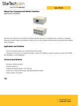
Figure 4: NSC200 top and bottom views
Control knob for:
• Velocity control
• Position control
• Channel selection
• Local or Remote
mode selection
Tri-color
status LED
Buttons to select:
• Velocity or
Position mode
• Switchbox
channel
P
Flat portion of
housing to seat
against optical
table
V
Mounting holes
for bolts to
optical table
Reset button
for RS-485
address
Specifications
Number of controlled axes 1 without NSC-SB switchbox
8 with NSC-SB switchbox
Operating modes 1. Manual velocity mode.
2. Manual position mode.
3. Computer controlled mode.
Selection of manual or computer
Pressing down on control knob.
Controls, Local (manual) mode
1. Button to select velocity mode.
2. Button to select position mode.
3. Rotary knob to activate motion.
Controls, Remote (computer) mode ASCII commands I/O via RS485 port.
Power requirements
When driving positioner
In standby mode
0.7A @ 15 Vdc
0.3A @ 15 Vdc

Features & Specifications 19
Power output when driving positioner 400 mA @ 15 Vdc
Compatible positioners NSA12 linear actuator.
MFA-PP motorized linear stage.
Stepper motor control 64 micro-steps per full-step.
Connectors Coaxial mini jack for power input
6-position, 4-wire RJ11 jack for RS485
9-pin mini DIN, female, to positioner
Mechanical
Dimensions (W x D x H)
Weight
50 x 150 x 50 mm (2” x 6” x 2”)
250 g (9 oz)
Environmental See NewStep system specs
2.3 NSC-SB Switchbox
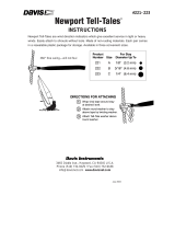
Figure 5: NSC-SB Switchbox, Front and Side
The NSC-SB switchbox is a intelligent multiplexer (or switch) which allows one
NSC200 controller to drive up to eight NewStep positioners one channel at a
time. The controller mode can be either Local or Remote. In Local mode, the
channel is selected by first simultaneously pressing the V and P buttons for five
seconds, then pressing the V and P buttons individually to increment or decre-
ment the channel. In Remote mode, the channel is selected under computer
control. In either mode, the status of each channel is indicated by the color of a
bank of tri-color LEDs labeled 1-8.

20 Features & Specifications
When used, switchbox serves as the connection hub between the power supply,
computer (if applicable), and positioners. The controller detects the presence of
the switchbox and automatically enables or disables functionalities as required.
•
Power. The switchbox is powered directly from the NSC-PS25 power
supply via first power cable, and in turn powers the associated controller via
a second power cable. The side of the switchbox features two coaxial mini
jacks, one labeled with a symbol for power in, one labeled Controller.
•
RS485 I/O. In Remote mode, the switchbox communicates with the com-
puter via a first RS485 cable, and in turn communicates with the controller
via a second RS485 cable. The side of the switchbox features two RJ11
jacks, one labeled PC, one labeled Controller. In Local mode, only the
RS485 cable to the controller is used.
•
Drive Signals. The switchbox can drive up to eight NewStep positioners,
and in turn is driven by the controller. The back of the switchbox features
eight female 9-pin mini-DIN connectors for positioner cables. The side of
the switchbox features a single female 9-pin mini-DIN connector for
connection to the controller.
Specifications
Positioner input channels 1 (multiplexed by switchbox)
Positioner output channels 8 (only selected channel is active)
Power requirements 15 Vdc, 40 mA
Channel status indication One tri-color LED per channel
Case dimensions (H x W x D) 35 x 182 x 151 mm (1.4” x 7.2” x 5.9”)
Case material Aluminum, painted.
Connector for power input Coaxial mini jack, positive center.
Connector to computer (if used) 6-position, 4-wire RJ11 for RS485 I/O.
Connectors to positioners 8 connectors, 9-pin mini-DIN, female.
Connectors to controller 6-position, 4-wire RJ11 for RS485 I/O.
Coaxial mini jack, positive center, for power.
9-pin mini-DIN, female, for drive signal.
/