Page is loading ...

Revision 1.3 Page i
ACM100
Alternating Current Monitor
User’s Manual
Revision 1.3
Copyright © 2014 Maretron, LLP All Rights Reserved
Maretron, LLP
9014 N. 23
rd
Ave #10
Phoenix, AZ 85021-7850
http://www.maretron.com
Maretron Manual Part #: M001701

ACM100 User’s Manual
Page ii Revision 1.3
Revision History
Revision
Description
1.0
Original document
1.1
Corrected AC sensor part number
Updated mounting drawing
1.2
Added sensed voltage and current range specifications
Added prohibition of red Loctite threadlocking compound and cleaning agents
containing acetone
1.3
Updated maximum voltage specifications
Added description of connection to three-phase delta circuits
Updated list of devices/programs that can be used for configuration
Updated transmission intervals of transmitted messages
Typographical corrections
Expanded PGN entries in Appendix A
Removed obsolete device priority subsection in configuration section
Added mechanical drawings for current transducer accessories

Revision 1.3 Page iii
Table of Contents
1 Introduction ........................................................................................................................... 1
1.1 Firmware Revision .................................................................................................... 1
1.2 ACM100 Features .................................................................................................... 1
1.3 ACM100 Accessories ............................................................................................... 2
1.4 Quick Install .............................................................................................................. 2
2 Installation ............................................................................................................................. 2
2.1 Unpacking the Box ................................................................................................... 2
2.2 Choosing a Mounting Location ................................................................................. 2
2.3 Mounting the ACM100 .............................................................................................. 2
2.4 Connecting the ACM100 .......................................................................................... 3
2.4.1 NMEA 2000
®
Connection............................................................................... 3
2.4.2 AC Sensor Connections ................................................................................ 4
2.4.2.1 Single-Phase (Phase A) Connection ................................................ 5
2.4.2.2 Single-Phase (Phase A, B) Connection ........................................... 6
2.4.2.3 Three-Phase Wye (Phase A, B, C) Connection ............................... 8
2.4.2.4 Three-Phase Delta (Phase A, B, C) Connection ............................ 10
2.4.3 Checking Connections ................................................................................. 12
2.5 Configuring the ACM100 ........................................................................................ 12
2.5.1 Advanced Configuration… ........................................................................... 12
2.5.1.1 Current Transducer A ..................................................................... 12
2.5.1.2 Current Transducer B ..................................................................... 13
2.5.1.3 Current Transducer C .................................................................... 13
2.5.1.4 Power Damping Period .................................................................. 13
2.5.1.5 V,I,F Damping Period ..................................................................... 13
2.5.1.6 Installation Description ................................................................... 13
2.5.1.7 NMEA 2000
®
PGN Enable/Disable ................................................ 13
2.5.1.8 Restore Factory Defaults ............................................................... 14
2.5.2 AC Circuit Type ............................................................................................ 14
2.5.3 AC Device Type ........................................................................................... 14
2.5.4 Device Instance ........................................................................................... 14
2.5.5 Label ............................................................................................................ 14
2.5.6 Reset Total Energy Recorded ...................................................................... 14
3 Output Parameters .............................................................................................................. 15
3.1 Line-Specific and Line-to-Neutral Measurements ................................................... 15
3.2 Line-to-Line Measurements .................................................................................... 15
4 Maintenance ........................................................................................................................ 16
5 Troubleshooting .................................................................................................................. 16
6 Technical Specifications ...................................................................................................... 17
7 Technical Support ............................................................................................................... 18
8 Installation Template ........................................................................................................... 19
9 Accessories Mechanical Drawings ...................................................................................... 20
10 Maretron (2 Year) Limited Warranty .................................................................................... 22

ACM100 User’s Manual
Page iv Revision 1.3
Table of Figures
Figure 1 – Mounting the ACM100 .............................................................................................. 3
Figure 2 – NMEA 2000
®
Connector Face Views ....................................................................... 4
Figure 3 – Single-Phase (Single Line) Connection Diagram ...................................................... 5
Figure 4 – Single-Phase (Dual Line) Connection Diagram ........................................................ 6
Figure 5 – Three-Phase Wye Connection Diagram ................................................................... 8
Figure 6 – Three-Phase Delta Connection Diagram ................................................................ 10
Figure 7 – Mounting Surface Template ................................................................................... 19
Figure 8 – M000530 100A Current Transducer ....................................................................... 20
Figure 9 – M000612 400A Current Transducer ....................................................................... 21
Table of Appendices
Appendix A – NMEA 2000
®
Interfacing .................................................................................... A1

Revision 1.3 Page 1
1 Introduction
Congratulations on your purchase of the Maretron Alternating Current (AC) Monitor (ACM100).
Maretron has designed and built your ACM100 to the highest standards for years of dependable
and accurate service.
Maretron’s ACM100 is a device which monitors AC power sources and outputs information about
these sources onto the industry standard NMEA 2000
®
marine data network. ACM100 output
information is then displayed with networked NMEA 2000
®
equipment such as the Maretron
DSM150/DSM250 dedicated display or with NMEA 2000
®
compatible software such as Maretron
N2KView. The ACM100 can sense voltages up to 380VAC (line-to-neutral) and currents up to
400A.
The Maretron ACM100 is designed to operate within the harsh demands of the marine
environment. However, no piece of marine electronic equipment can function properly unless
installed, configured, and maintained in the correct manner. Please read carefully and follow
these instructions for installation, configuration, and usage of the Maretron ACM100 in order to
ensure optimal performance.
1.1 Firmware Revision
This manual corresponds to ACM100 firmware revision 1.0.9.2.
1.2 ACM100 Features
The Maretron ACM100 has the following features.
NMEA 2000
®
Interface
Waterproof Connectors
Sealed Waterproof Enclosure
Opto-Isolated from NMEA 2000
®
Eliminating Potential Ground Loops
Monitoring of busses carrying AC power and transmitting
o Voltage
o Frequency
Monitoring AC Power Sources such as Utilities and Generators and transmitting:
o Voltage
o Current
o Frequency
o Real Power
o Reactive Power
o Apparent Power
o Power Factor
o Total Energy Imported
o Total Energy Exported
Can be used in the following configurations
o 120VAC single phase
o 120/240VAC split-phase
o 230VAC single phase

ACM100 User’s Manual
Page 2 Revision 1.3
o Three-phase Wye (4-wire) up to (380/658Y)
o Three-phase Delta (3-wire) up to 660V
1.3 ACM100 Accessories
Maretron offers the following accessories for the ACM100 (please refer to Section ? for
dimensions):
M000630 100 Amp AC transducer with cable
M000612 400 Amp AC transducer with cable
1.4 Quick Install
Installing the Maretron ACM100 involves the following five steps. Please refer to the individual
sections for additional details.
1. Unpack the box (Section 2.1)
2. Choose a mounting location (Section 2.2)
3. Mount the ACM100 (Section 2.3)
4. Connect the ACM100 (Section 2.4)
5. Configure the ACM100 (Section 2.5)
2 Installation
2.1 Unpacking the Box
When unpacking the box containing the Maretron ACM100, you should find the following items:
1 – ACM100 – AC Monitor
1 – 100A AC Current Transducer with 5 ft. (1.5m) long cable (Part # M000630)
1 – Parts Bag containing 4 Stainless Steel Mounting Screws
1 – ACM100 User’s Manual
1 – Warranty Registration Card
If any of these items are missing or damaged, please contact Maretron.
2.2 Choosing a Mounting Location
Please consider the following when choosing a mounting location.
1. The ACM100 is waterproof, so it can be mounted in a damp or dry location.
2. The orientation is not important, so the ACM100 can be mounted on a horizontal deck,
vertical bulkhead, or upside down if desired.
3. The ACM100 is temperature rated to 55°C (130°F), so it should be mounted away from
engines or engine rooms where the operating temperature exceeds the specified limit.
2.3 Mounting the ACM100
Attach the ACM100 securely to the vessel using the included stainless steel mounting screws
or other fasteners as shown in Figure 1 below. Do not use threadlocking compounds containing

Revision 1.3 Page 3
methacrylate ester, such as Loctite Red (271), as they will cause stress cracking of the plastic
enclosure.
Figure 1 – Mounting the ACM100
2.4 Connecting the ACM100
The ACM100 requires two types of electrical connections: 1) the NMEA 2000
®
connection
(refer to Section 2.4.1), and 2) the AC sensor connections (i.e., current transducer(s) and
sensing voltage(s) connections), which are described in Section 2.4.2.
2.4.1 NMEA 2000
®
Connection
The NMEA 2000
®
connector can be found on the side of the enclosure. The NMEA 2000
®
connector is a round five pin male connector (see Figure 2). You connect the ACM100 to an
NMEA 2000
®
network using a Maretron NMEA 2000
®
cable (or compatible cable) by connecting
the female end of the cable to the ACM100 (note the key on the male connector and keyway on
the female connector). Be sure the cable is connected securely and that the collar on the cable
connector is tightened firmly. Connect the other end of the cable (male) to the NMEA 2000
®
network in the same manner. The ACM100 is designed such that you can plug or unplug it from
an NMEA 2000
®
network while the power to the network is connected or disconnected. Please
follow recommended practices for installing NMEA 2000
®
network products.

ACM100 User’s Manual
Page 4 Revision 1.3
Figure 2 – NMEA 2000
®
Connector Face Views
2.4.2 AC Sensor Connections
The ACM100 sensor connections are made by connecting to the 12-pin terminal strip on the top
of the unit. First, remove the four screws at the corners of the unit detaching the splash guard
from the unit. On the bottom of the splash guard, you will find a label detailing the wire connection
to pin number assignments, which are repeated in the table below.
Pin #
Signal Name
Connection
1
V
A
Line
Voltage Phase A Line
2
V
B
Line
Voltage Phase B Line
3
V
C
Line
Voltage Phase C Line
4
V
A
Neutral
Voltage Phase A Neutral
5
V
B
Neutral
Voltage Phase B Neutral
6
V
C
Neutral
Voltage Phase C Neutral
7
I
A+
Current Phase A Plus
8
I
A-
Current Phase A Minus
9
I
B+
Current Phase B Plus
10
I
B-
Current Phase B Minus
11
I
C+
Current Phase C Plus
12
I
C-
Current Phase C Minus
WARNING: The voltages present on AC circuits can cause electrocution.
Before making any electrical connections to the ACM100, ensure that power is
removed from all AC circuits that will be connected to the ACM100. Only restore
AC power after all connections have been made to the ACM100 and the splash
guard has been re-installed.

Revision 1.3 Page 5
WARNING: If the supplied current transducer is placed around a wire carrying
AC current, then extremely high voltages can develop on the output leads of
the current transducer, with severe risk of electrocution. For safety, keep the
output leads of the current transducer(s) shorted or tied together until they are
connected to the proper terminals on the ACM100.
WARNING: User supplied voltage sense cables must be 18 gauge or larger,
have insulation rated to 600V, and must have the conductor connected to the
hot lead of the AC power source protected by a fuse rated at 3A or less (the
current consumed by the voltage sense circuit on the ACM100 is negligible, at
less than 10mA).
Before attempting to connect the ACM100 to the AC source, determine the type of system you
will be monitoring. The ACM100 supports the connection and monitoring of four different system
types; 1) single-phase single line system (Section 2.4.2.1), 2) single-phase dual line system
(Section 2.4.2.2), 3) three-phase wye connected system (Section 2.4.2.3), or 4) three-phase
delta connected system (Section 2.4.2.4).
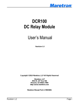
2.4.2.1 Single-Phase (Phase A) Connection
Please refer to Figure 3 for connecting the ACM100 to a single phase, single line system.
Figure 3 – Single-Phase (Single Line) Connection Diagram
Use the following instructions when you are connecting the ACM100 to a single-phase circuit
connected via one (hot) phase wire and one neutral wire. You will need to install one current
transducer and one voltage sense cable.
Step 1: De-energize the AC Source.
Line (Phase A)
Neutral
U.S.
120 Volts
60Hz
+
-
Europe
220 Volts
50Hz
+
-
AC Source
1
2
5
4
3
6
7
8
9
10
11
12
Fuse
V
A
Line
V
A
Neutral
Current
Transducer
ACM100 Screw Terminals
V
B
Line
V
C
Line
V
B
Neutral
V
C
Neutral
I
A+
I
A-
I
B+
I
B-
I
C+
I
C-

ACM100 User’s Manual
Page 6 Revision 1.3
Step 2: The Current Transducer has black and white wires. Install the Current Transducer as
follows:
a. Connect the black wire to pin 7 (I
A+
) on the ACM100
b. Connect the white wire to pin 8 (I
A-
) on the ACM100
c. Disconnect the hot wire from the AC power source and place it through the hole in the
Current Transducer such that the arrow on the Current Transducer points towards the
AC power source. Then, reattach the hot wire to the AC source.
Step 3: You must supply a cable for connecting the voltage sense pins on the ACM100 to the
AC source. For the purposes of these instructions, we will assume that the cable has one black
conductor and one white conductor. Install the voltage sense cable as follows:
a. Connect the white wire from one end of the Voltage Sense cable to pin 4 (V
ANeutral
) on
the ACM100.
b. Connect the white wire from the other end of the Voltage Sense cable to the neutral
wire of the AC source being monitored.
c. Connect the black wire from one end of the Voltage Sense cable to pin 1 (V
ALine
) on
the ACM100
d. Connect the black wire from the other end of the Voltage Sense cable to a fuse
appropriately sized for the black wire (18 gauge wire minimum and 3 amp fuse or
less).
e. Connect the other end of the fuse to the AC source hot wire (the fuse should be placed
within 6 inches of the connection to the hot wire).
2.4.2.2 Single-Phase (Phase A, B) Connection
Please refer to Figure 4 for connecting the ACM100 to a single phase, dual line system.
Figure 4 – Single-Phase (Dual Line) Connection Diagram
V
A
Line
V
A
Neutral
V
B
Line
V
C
Line
V
B
Neutral
V
C
Neutral
I
A+
I
A-
I
B+
I
B-
I
C+
I
C-
Line (Phase A)
Neutral
U.S.
120 Volts
60Hz
+
-
Europe
220 Volts
50Hz
+
-
AC Source
1
2
5
4
3
6
7
8
9
10
11
12
Fuse
Current
Transducer
ACM100 Screw Terminals
Fuse
Line (Phase B)
Current
Transducer

Revision 1.3 Page 7
Use the following instructions when you are connecting the ACM100 to a single-phase circuit
connected via two hot wires. You will need to install two current transducer and two user-supplied
voltage sense cables. The ACM100 comes with a single current transducer so you will need to
purchase an additional current transducer (please refer to Section 1.3) for monitoring this type
of system.
Step 1: De-energize the AC Source.
Step 2: The Current Transducer has black and white wires. Install the Phase A Current
Transducer as follows:
a. Connect the black wire to pin 7 (I
A+
) on the ACM100
b. Connect the white wire to pin 8 (I
A-
) on the ACM100
c. Disconnect the Phase A hot wire from the AC power source and place it through the
hole in the Current Transducer such that the arrow on the Current Transducer points
towards the AC power source. Then, reattach the hot wire to the AC power source.
Step 3: Repeat step 2 for the Phase B Current Transducer as follows:
a. Connect the black wire to pin 9 (I
B+
) on the ACM100
b. Connect the white wire to pin 10 (I
B-
) on the ACM100
c. Disconnect the Phase B hot wire from the AC power source and place it through the
hole in the Current Transducer such that the arrow on the Current Transducer points
towards the AC power source. Then, reattach the hot wire to the AC power source.
Step 4: You must supply cables for connecting the voltage sense pins on the ACM100 to the
AC source. For the purposes of these instructions, we will assume that each cable has one black
conductor and one white conductor. Install the first voltage sense cable as follows:
a. Connect the white wire from one end of the first Voltage Sense cable to pin 4 (V
ANeutral
)
on the ACM100.
b. Connect the white wire from the other end of the first Voltage Sense cable to the
neutral wire of the AC source being monitored
c. Connect the black wire from one end of the first Voltage Sense cable to pin 1 (V
ALine
)
on the ACM100
d. Connect the black wire from the other end of the first Voltage Sense cable to a fuse
appropriately sized for the black wire (18 gauge wire minimum and 3 amp fuse or
less).
e. Connect the other end of the fuse to the AC source hot wire (the fuse should be placed
within 6 inches of the connection to the hot wire).
Step 5: Install the second Voltage Sense cable as follows:
a. Connect the white wire from one end of the second Voltage Sense cable to pin 5
(V
BNeutral
) on the ACM100.
b. Connect the white wire from the other end of the second Voltage Sense cable to the
neutral wire of the AC source being monitored.
c. Connect the black wire from one end of the second Voltage Sense cable to pin 2
(V
BLine
) on the ACM100

ACM100 User’s Manual
Page 8 Revision 1.3
d. Connect the black wire from the other end of the second Voltage Sense cable to a
fuse appropriately sized for the black wire (18 gauge wire minimum and 3 amp fuse
or less).
e. Connect the other end of the fuse to the AC source hot wire (the fuse should be placed
within 6 inches of the connection to the hot wire).
2.4.2.3 Three-Phase Wye (Phase A, B, C) Connection
Please refer to Figure 5 for connecting the ACM100 to a three phase wye system.
Figure 5 – Three-Phase Wye Connection Diagram
Use the following instructions when you are connecting the ACM100 to a three-phase “Wye”
circuit connected via three hot wires and a single neutral. You will need to install three current
transducers and three user-supplied voltage sense cables. The ACM100 comes with a single
current transducer so you will need to purchase two additional current transducers for monitoring
this type of system.
Step 1: De-energize the AC Source.
Step 2: The Current Transducer has black and white wires. Install the first Current Transducer
as follows:
a. Connect the black wire to pin 7 (I
A+
) on the ACM100
b. Connect the white wire to pin 8 (I
A-
) on the ACM100
c. Disconnect the Phase A hot wire from the AC power source and place it through the
hole in the Current Transducer such that the arrow on the Current Transducer points
Line (Phase A)
Neutral
U.S.
120 Volts
60Hz
+
-
Europe
220 Volts
50Hz
+
-
AC Source
1
2
5
4
3
6
7
8
9
10
11
12
Fuse
V
A
Line
V
A
Neutral
Current
Transducer
ACM100 Screw Terminals
V
B
Line
V
C
Line
V
B
Neutral
V
C
Neutral
I
A+
I
A-
I
B+
I
B-
I
C+
I
C-
Fuse
Current
Transducer
Fuse
Current
Transducer
Line (Phase B)
Line (Phase C)

Revision 1.3 Page 9
towards the AC power source. Then, reattach the Phase A hot wire to the AC power
source.
Step 3: Install the second Current Transducer as follows:
a. Connect the black wire to pin 9 (I
B+
) on the ACM100
b. Connect the white wire to pin 10 (I
B-
) on the ACM100
c. Disconnect the Phase B hot wire from the AC power source and place it through the
hole in the Current Transducer such that the arrow on the Current Transducer points
towards the AC power source. Then, reattach the Phase B hot wire to the AC power
source.
Step 4: Install the third Current Transducer as follows:
a. Connect the black wire to pin 11 (I
C+
) on the ACM100
b. Connect the white wire to pin 12 (I
C-
) on the ACM100
c. Disconnect the Phase C hot wire from the AC power source and place it through the
hole in the Current Transducer such that the arrow on the Current Transducer points
towards the AC power source. Then, reattach the Phase C hot wire to the AC power
source.
Step 5: You must supply a cable for connecting the voltage sense pins on the ACM100 to the
AC source. For the purposes of these instructions, we will assume that the cable has one black
conductor and one white conductor. Install the voltage sense cable as follows:
a. Connect the white wire from one end of the Voltage Sense cable to pin 4 (V
ANeutral
) on
the ACM100.
b. Connect the white wire from the other end of the Voltage Sense cable to the neutral
wire of the AC source being monitored.
c. Connect the black wire from one end of the Voltage Sense cable to pin 1 (V
ALine
) on
the ACM100
d. Connect the black wire from the other end of the Voltage Sense cable to a fuse
appropriately sized for the black wire (18 gauge wire minimum and 3 amp fuse or
less).
e. Connect the other end of the fuse to the AC source hot wire (the fuse should be placed
within 6 inches of the connection to the hot wire).
Step 6: Install the second Voltage Sense cable as follows:
a. Connect the white wire from one end of the second Voltage Sense cable to pin 5
(V
BNeutral
) on the ACM100.
b. Connect the white wire from the other end of the second Voltage Sense cable to the
neutral wire of the AC source being monitored.
c. Connect the black wire from one end of the second Voltage Sense cable to pin 2
(V
BLine
) on the ACM100
d. Connect the black wire from the other end of the second Voltage Sense cable to a
fuse appropriately sized for the black wire (18 gauge wire minimum and 3 amp fuse
or less).
e. Connect the other end of the fuse to the AC source hot wire (the fuse should be placed
within 6 inches of the connection to the hot wire).

ACM100 User’s Manual
Page 10 Revision 1.3
Step 7: Install the third Voltage Sense cable as follows:
a. Connect the white wire from one end of the second Voltage Sense cable to pin 6
(V
CNeutral
) on the ACM100.
b. Connect the white wire from the other end of the second Voltage Sense cable to the
neutral wire of the AC source being monitored.
c. Connect the black wire from one end of the second Voltage Sense cable to pin 3
(V
CLine
) on the ACM100
d. Connect the black wire from the other end of the second Voltage Sense cable to a
fuse appropriately sized for the black wire (18 gauge wire minimum and 3 amp fuse
or less).
e. Connect the other end of the fuse to the AC source hot wire (the fuse should be placed
within 6 inches of the connection to the hot wire).
2.4.2.4 Three-Phase Delta (Phase A, B, C) Connection
Please refer to Figure 6 for connecting the ACM100 to a three phase delta system.
Figure 6 – Three-Phase Delta Connection Diagram
Use the following instructions when you are connecting the ACM100 to a three-phase delta
circuit connected via three hot wires. You will need to install three current transducers and three
user-supplied voltage sense cables. The ACM100 comes with a single current transducer so
you will need to purchase two optional current transducers (please refer to Section 1.3) for
monitoring this type of system.
Step 1: De-energize the AC Source.
Line (Phase A)
“Floating”
Neutral
Max
380 Volts
50-60Hz
+
-
AC Source
1
2
5
4
3
6
7
8
9
10
11
12
Fuse
V
A
Line
V
A
Neutral
Current
Transducer
ACM100 Screw Terminals
V
B
Line
V
C
Line
V
B
Neutral
V
C
Neutral
I
A+
I
A-
I
B+
I
B-
I
C+
I
C-
Fuse
Current
Transducer
Fuse
Current
Transducer
Line (Phase B)
Line (Phase C)

Revision 1.3 Page 11
Step 2: The Current Transducer has black and white wires. Install the first Current Transducer
as follows:
a. Connect the black wire to pin 7 (I
A+
) on the ACM100
b. Connect the white wire to pin 8 (I
A-
) on the ACM100
c. Disconnect the Phase A hot wire from the AC power source and place it through the
hole in the Current Transducer such that the arrow on the Current Transducer points
towards the AC power source. Then, reattach the Phase A hot wire to the AC power
source.
Step 3: Install the second Current Transducer as follows:
a. Connect the black wire to pin 9 (I
B+
) on the ACM100
b. Connect the white wire to pin 10 (I
B-
) on the ACM100
c. Disconnect the Phase B hot wire from the AC power source and place it through the
hole in the Current Transducer such that the arrow on the Current Transducer points
towards the AC power source. Then, reattach the Phase B hot wire to the AC power
source.
Step 4: Install the third Current Transducer as follows:
a. Connect the black wire to pin 11 (I
C+
) on the ACM100
b. Connect the white wire to pin 12 (I
C-
) on the ACM100
c. Disconnect the Phase C hot wire from the AC power source and place it through the
hole in the Current Transducer such that the arrow on the Current Transducer points
towards the AC power source. Then, reattach the Phase C hot wire to the AC power
source.
Step 5: You must supply a cable for connecting the voltage sense pins on the ACM100 to the
AC source. For the purposes of these instructions, we will assume that the cable has one black
conductor and one white conductor. Install the voltage sense cable as follows:
a. Connect the black wire from one end of the Voltage Sense cable to pin 1 (V
ALine
) on
the ACM100
b. Connect the black wire from the other end of the Voltage Sense cable to a fuse
appropriately sized for the black wire (18 gauge wire minimum and 3 amp fuse or
less).
c. Connect the other end of the fuse to the AC source hot wire (the fuse should be placed
within 6 inches of the connection to the hot wire).
Step 6: Install the second Voltage Sense cable as follows:
a. Connect the black wire from one end of the second Voltage Sense cable to pin 2
(V
BLine
) on the ACM100
b. Connect the black wire from the other end of the second Voltage Sense cable to a
fuse appropriately sized for the black wire (18 gauge wire minimum and 3 amp fuse
or less).
c. Connect the other end of the fuse to the AC source hot wire (the fuse should be placed
within 6 inches of the connection to the hot wire).
Step 7: Install the third Voltage Sense cable as follows:

ACM100 User’s Manual
Page 12 Revision 1.3
a. Connect the black wire from one end of the second Voltage Sense cable to pin 3
(V
CLine
) on the ACM100
b. Connect the black wire from the other end of the second Voltage Sense cable to a
fuse appropriately sized for the black wire (18 gauge wire minimum and 3 amp fuse
or less).
c. Connect the other end of the fuse to the AC source hot wire (the fuse should be placed
within 6 inches of the connection to the hot wire).
Step 8: Connect the neutral terminals as follows:
a. Connect a white wire between pin 4 (V
ANeutral
), pin 5 (V
BNeutral
), and pin 6 (V
CNeutral
) on
the ACM100. This creates a “floating neutral” signal that will enable measurements to
be made without a true neutral connection.
2.4.3 Checking Connections
Once the NMEA 2000
®
connection, Current Transducer(s), and Voltage Sense connection(s) to
the ACM100 have been completed, restore power to the monitored AC source and check to see
that information is being properly transmitted by observing an appropriate NMEA 2000
®
display.
If you don’t see AC power data, refer to Section 5, “Troubleshooting”.
2.5 Configuring the ACM100
The ACM100 will transmit data over the NMEA 2000 network as it is shipped from the factory;
however, it may require configuration, depending on the type of AC source being monitored.
There are several configurable items within the ACM100, which are detailed in the remainder of
this section.
You configure the ACM100 using Maretron N2KAnalyzer
®
software or a Maretron
DSM150/DSM250 display. Please refer to the N2KAnalyzer User’s Manual, DSM150 User’s
Manual, or DSM250 User’s Manual, as appropriate, for details.
2.5.1 Advanced Configuration…
Certain parameters do not normally need to be set in order for normal operation, but are included
in an advanced configuration section for use in special situations.
2.5.1.1 Current Transducer A
There are two configurable items for Current Transducer A: amperage and direction.
If you are using the 100A current transducer (P/N #M000630), select the 100A option. If you are
using the 400A current transducer (P/N #M000612), select the 400A option.
For the direction setting, if you notice that the current of phase A is negative when it should be
positive, or vice-versa, then the current transducer has been installed backwards. If this
happens, then instead of reconnecting the current transducer, you may change the value of this
parameter from the default value of “Normal Install” to “Inverse Install” to correct for this.

Revision 1.3 Page 13
2.5.1.2 Current Transducer B
There are two configurable items for Current Transducer B: amperage and direction.
If you are using the 100A current transducer (P/N #M000630), select the 100A option. If you are
using the 400A current transducer (P/N #M000612), select the 400A option.
For the direction setting, if you notice that the current of phase B is negative when it should be
positive, or vice-versa, then the current transducer has been installed backwards. If this
happens, then instead of reconnecting the current transducer, you may change the value of this
parameter from the default value of “Normal Install” to “Inverse Install” to correct for this.
2.5.1.3 Current Transducer C
There are two configurable items for Current Transducer A: amperage and direction.
If you are using the 100A current transducer (P/N #M000630), select the 100A option. If you are
using the 400A current transducer (P/N #M000612), select the 400A option.
For the direction setting, if you notice that the current of phase C is negative when it should be
positive, or vice-versa, then the current transducer has been installed backwards. If this
happens, then instead of reconnecting the current transducer, you may change the value of this
parameter from the default value of “Normal Install” to “Inverse Install” to correct for this.
2.5.1.4 Power Damping Period
If you feel that the monitored Power parameters are changing too quickly or too slowly on the
display, you can adjust the damping that is applied to the output readings by adjusting this
parameter. . The default damping period is 5 seconds. . You may change it to a value in the
range of 0.2 seconds to 10 seconds.
2.5.1.5 V,I,F Damping Period
If you feel that the monitored Voltage, Current, and Frequency parameters are changing too
quickly or too slowly on the display, you can adjust the damping that is applied to the output
readings by adjusting this parameter. . The default damping period is 0.5 seconds. . You may
change it to a value in the range of 0.2 seconds to 10 seconds.
2.5.1.6 Installation Description
You can configure the two installation description parameters with any text you wish. Examples
include date of installation, location, etc. NMEA 2000 diagnostic tools such as Maretron
N2KAnalyzer
®
can display this information.
2.5.1.7 NMEA 2000
®
PGN Enable/Disable
The ACM100 is capable of transmitting many different kinds of NMEA 2000
®
messages (or
PGNs) associated with AC power sources. You may individually enable or disable each of these
messages. You may also change the rate of transmission of each of these messages if desired.

ACM100 User’s Manual
Page 14 Revision 1.3
2.5.1.8 Restore Factory Defaults
Selecting this configuration option causes all stored parameters in the ACM100 to be reset to
the values they contained when the unit was manufactured.
2.5.2 AC Circuit Type
You must configure the ACM100 as to what type of AC circuit connection it is monitoring. The
allowable values for this parameter are as follows:
Single-Phase (Phase A) – use this value when power is connected via a single hot wire
and a single neutral wire (a typical 110VAC connection in the US).
Single-Phase (Phase A, B) – use this value when power is connected via the two hot
wires and single neutral wire from a single phase of a transducer (a typical 220VAC
connection in the US).
Three-Phase (Phase A, B, C) – use this value when power is connected via the three
hot wires and single neutral wire from a three-phase “Wye” or “Delta” connected circuit.
2.5.3 AC Device Type
You must configure the ACM100 as to what type of AC source it is monitoring. The allowable
values for this parameter are as follows:
“Generator” (default) – use this value when you are monitoring the output of a genset.
“Utility” – use this value when you are monitoring shore power
“Bus” – use this value if you are monitoring power flowing across a cable that is not
located directly at the output of a genset or a shore power connection (e.g., an AC
selection switch might have as an input the shore power and another input from the
genset, connecting the ACM100 at the output of the AC selection switch would require
the ACM100 to be configured as “Bus”.
2.5.4 Device Instance
NMEA 2000
®
provides a unique AC power instance for each AC power source on a vessel. This
value should be programmed in each ACM100 so that each ACM100 is associated with a unique
device instance number. The default instance number is 0, which is used to indicate the first
ACM100 that is hooked to the network. Subsequent ACM100s connected to the network would
be numbered 1, 2, and so on.
2.5.5 Label
Program this parameter with a text string which identifies this device. Maretron display
products will display this label text when you are selecting data to display.
2.5.6 Reset Total Energy Recorded
The ACM100 accumulates the total energy imported from a Utility and exported from a
generator. Select this option to zero the total energy accumulated readings in the ACM100.

Revision 1.3 Page 15
3 Output Parameters
The ACM100 outputs a variety of information about the AC power source onto the NMEA 2000
network. The tables below detail which measurements are made available on the bus for the
different combinations of different AC source types and circuit types which may be selected.
3.1 Line-Specific and Line-to-Neutral Measurements
Parameter
AC Source Type
Available Data
Bus
Generator
Utility
Average
Phase A
Phase B
Phase C
Line-Neutral AC
RMS Voltage
1
2
AC RMS Current
1
2
AC Frequency
1
2
Real Power
1
2
Apparent Power
1
2
Reactive Power
1
2
Power Factor
1
2
Total kW Hours
Export
Total kW Hours
Import
Notes:
1. Available only if circuit type has been set to “Single-Phase (Phase A,B)” or
“Three-Phase (Phase A,B,C)”
2. Available only if circuit type has been set to “Three-Phase (Phase A,B,C)”
3.2 Line-to-Line Measurements
Parameter
AC Source Type
Available Data
Bus
Generator
Utility
Average
Phase A
to
Phase B
Phase B
to
Phase C
Phase C
to
Phase A
Line-Line AC RMS
Voltage
1
2
2
Notes:
1. Available only if circuit type has been set to “Single-Phase (Phase A,B)” or
“Three-Phase (Phase A,B,C)”
2. Available only if circuit type has been set to “Three-Phase (Phase A,B,C)”

ACM100 User’s Manual
Page 16 Revision 1.3
4 Maintenance
Regular maintenance is important to ensure continued proper operation of the Maretron
ACM100. Perform the following tasks periodically:
Clean the unit with a soft cloth. Do not use chemical cleaners as they may remove paint
or markings or may corrode the ACM100 enclosure or seals. Do not use any cleaners
containing acetone, as they will deteriorate the plastic enclosure.
Ensure that the unit is mounted securely and cannot be moved relative to the mounting
surface. If the unit is loose, tighten the mounting screws.
Check the security of the cable connected to the NMEA 2000
®
connector, and tighten if
necessary.
Check the security of all of the current transducer connections and voltage transducer
connections on the top of the unit and tighten if necessary.
5 Troubleshooting
If you notice unexpected operation of the Maretron ACM100, follow the troubleshooting
procedures in this section to remedy simple problems. If these steps do not solve your problem,
please contact Maretron Technical Support (refer to Section 7 for contact information).
Symptom
Troubleshooting Procedure
No AC power data
visible on NMEA 2000
®
network.
Ensure that the ACM100 is properly connected to the NMEA
2000
®
network.
Ensure that the current transducers and voltage sense cables are
properly connected to the ACM100.
Ensure that the ACM100 has the appropriate NMEA 2000
®
PGNs
enabled as described in Section 1.
Exported power is
increasing when it
shouldn’t be
Imported power in not
increasing when it
should be
Currents are showing
as negative values
when they should be
showing as positive
values
The current transducer(s) are installed backwards. Either 1)
reinstall the current transducers in the opposite direction of 2)
configure the ACM100 to recognize the reversed installation as
described in Sections 1, 1, and 1.
Power readings are not
what I expect
Please review carefully the installation instructions in Section
2.4.2 and the configuration of the circuit type in Section 0.
/