Page is loading ...

CT146 – 10” TABLE SAW

2
INDEX
GENERAL SAFETY INSTRUCTIONS…………………………………………………………PAGE 3
SPECIFIC SAFETY INSTRUCTIONS……………………………………………………….PAGE 4-6
Grounding Information……………………………………………………………………………PAGE 7
Changing from 110V to 220V……………………………………………………………………PAGE 8
Introduction & Features…………………………………………………………………………..PAGE 9
Loose Parts Diagram…………………………………………………………………………PAGE 10-11
ASSEMBLY INSTRUCTIONS
Removing Hardware & Parts……………………………………………………………..……..PAGE 12
Assembly of Legs & Stand…………………………………………………………..…….PAGE 13 – 14
Mounting the Table to Stand…………………………………………………………………….PAGE 15
Installing the Extension Tables………………………………………………………………….PAGE 16
Installing the Bevel Adjusting Hand Wheel…………………………………………………….PAGE 17
Installing the Height Adjusting Hand Wheel……………………………………………………PAGE 18
Installing the Front Rail to Table……………………………………………………………...…PAGE 19
Installing the Back Rail to Table……………………………………………………..……PAGE 20 – 21
Adjusting the Front & Back Rails………………………………………………………………..PAGE 22
Installing the Rip Fence…………………………………………………………………………..PAGE 23
Aligning the Throat Plate…………………………………………………………………………PAGE 24
Installing the Spacer Bar…………………………………………………………………………PAGE 25
Installing the Blade Guard Assembly………………………………………………...…………PAGE 26
Aligning the Blade Guard Assembly & the Blade……………………………………...………PAGE 27
Mounting the Motor Assembly…………………………………………………………………..PAGE 28
Installing the Belt Guard………………………………………………………………………….PAGE 29
Installing the Belt………………………………………………………………………………….PAGE 30
Installing the Switch Assembly…………………………………………………………………..PAGE 31
Securing the Electrical Cords…………………………………………………….……..……….PAGE 32
Installing the End Caps of Fence……………………………………………….……………….PAGE 33
Troubleshooting……………………………………………………………………..…………….PAGE 34
Maintenance……………………………………………………………………………………….PAGE 35
SCHEMATIC DIAGRAMS & PARTS LIST
Miter Gauge Assembly……………………………………………………………….………PAGE 36-37
Stand Assembly……………………………………………………………………………….PAGE 38-39
Rip Fence Assembly………………………………………………………………………….PAGE 40-41
Blade Guard Assembly……………………………………………………………………….PAGE 42-43
Motor Assembly……………………………………………………………………...………..PAGE 44-45
Main Housing Assembly……….…………………………………………………...………..PAGE 46-47
Table Assembly……………………………………………………………………………….PAGE 48-49
Internal Body Assembly………………………………………………………………………PAGE 50-52
Warranty Information……………………………………………………………………………..PAGE 53

3
GENERAL SAFETY INSTRUCTIONS
Extreme caution should be used when operating all power tools.
Know your power tool, be familiar with its operation, read through the owner’s
manual and practice safe usage procedures at all times.
• CONNECT your machine ONLY to the matched and specific power source.
• ALWAYS WEAR SAFETY GLASSES, RESPIRATORS, HEARING
PROTECTION AND SAFETY SHOES when operating your machine.
• DO NOT WEAR LOOSE CLOTHING OR JEWELLERY when operating your
machine.
• A SAFE ENVIRONMENT IS IMPORTANT. Keep the area free of dust, dirt and
other debris in the immediate vicinity of your machine.
• BE ALERT! Do not use prescription or other drugs that may affect your ability
or judgment to safely use your machine.
• DISCONNECT the power source when changing drill bits, hollow chisels, router
bits, shaper heads, blades, knives or making other adjustments or repairs.
• NEVER leave a tool unattended while it is in operation.
• NEVER reach over the table when the tool is in operation.
• NEVER make crosscuts with the rip fence in place.
• NEVER attempt to cut material that is warped or twisted.
• NEVER attempt a procedure if it does not feel safe or comfortable.
• ALWAYS keep blades, knives and bits sharpened and properly aligned.
• ALWAYS keep all safety guards in place and ensure their proper function.
• ALWAYS use push sticks and feather boards to safely feed your work though
the machine.
• ALWAYS make sure that any tools used for adjustments are removed before
operating the machine.
• ALWAYS secure your work with the appropriate clamps or vises.
• ALWAYS keep bystanders safely away while the tool is in operation.
THINK SAFETY. WORK SAFELY.

4

5

6

7
GROUNDING
To prevent possible electrical hazards, have a qualified electrician ensure that
the line is properly wired. This machine is pre-wired to be use with a 120 volt
power supply and ensure the cord is plugged into a grounded power outlet.

8
CHANGING FROM 110V TO 220V
This table saw is pre-wired for 110V, 60 Hz. The following diagrams will help
explain the procedure to change over from 110V to 220V. The use of a qualified
technician is needed for this procedure.
First, unplug the saw. Located on the top of the junction box, remove the Philips
screw at the back of the junction box and lift off the cover.
Remove the electric holding tape from the wire connectors and remove the wire
connectors at the same time. Reconnect the leads and re-install the wire
connector. Wrap each wire with new UL approved electrical tape, 2 layers is
sufficient.
Recheck your wiring diagrams and reinstall the junction box cover using the
Phillips screw. At this point cut off the 110V power cord plug and replace it with a
3-prong 220 V 15AMP UL approved plug. Connect the power cord white and
black leads respectively to the hot plug blade terminals. Connect the green
grounding wire to the plug ground prong terminal.
You can now plug your saw into a 220-240V, 15 amp, 3-prong receptacle.
You need to ensure that the power supply is a 240V branch circuit having at least
15 amp capacity and is protected by a 15 amp time-delay fuse or circuit breaker.

9
INTRODUCTION
As part of a growing line of Craftex Woodworking Equipment, we are proud to
introduce the CT146 10” Contractors Table Saw. This is a professional
woodworking tool and like all tools, proper care and safety precautions should be
exercised at all times. Please read this manual and adhere to all safety rules
when using this machine. With proper care and safety techniques you should
receive years of excellent service from this well built table saw.
FEATURES
Motor – 1.5HP, 120/240V,60Hz,13/6.5 Amps
Blade Diameter – 10”
Blade Arbor – 5/8”
Cutting Depth at 0° - 3 3/8”
Cutting Depth at 45° - 2 ¼”
No Load Speed – 3,450 RPM
Large Blade Raising and Tilting Wheels
Precision Ground Cast-Iron Table
Precision Ground Cast Iron Extension
Tables
Precision Aluminum Rip Fence with micro
adjustment
Rip Fence Hooks for Storage
‘T’ Slot Mitre Gauge.
Sturdy Steel Stand
Optional Mount Safety Power Switch
Net Weight – 120.5 Kg
Shipping Weight – 127 Kg

10
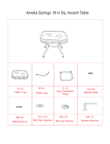
LOOSE PARTS OF MACHINE

11
LOOSE PARTS OF MACHINE

12
ASSEMBLY
Carefully remove the all components and place it carefully on a level and stable
work surface. This tool is heavy and it is recommended that you use the help of a
friend to lifting heavy components.
Remove any protective oil, grease that has been applied to the unpainted metal
surfaces. Household cleaners and spot removers should work fine here.
You will now want to apply a coat of paste wax to the table and table extensions.
Do not discard your packaging until you have carefully inspected your table saw,
identified all loose parts and have properly operated the tool.
WARNING – DO NOT lift this saw without the help of another person. Hold the saw with a firm
grip and close to your body to ensure that you or the saw does not slip while being handled.
Be as careful as possible to prevent back injury.
WARNING – If any parts are found to be damaged of missing do not being assembly or
attempt to operate this tool. Failure to do so may result in serious personal injury

13
ASSEMBLY
Assembly of Legs & Stand
Locate the following parts
15 Hex Nuts, Flanged (5/16 – 18)
15 Carriage Bolts (5/15-18 x 5/8”)
8 Hex Nuts (3/8-16)
Place the front brace inside the first leg piece & align the holes on the leg piece
with the front brace. At this time, insert two carriage bolts and hand tighten only
using the flanged hex nuts.
See Figure 1
Figure 1

14
ASSEMBLY
Now you can attach the second leg piece to the other side of the front brace
using another two carriage bolts and flanged hex nuts, same as show above.
Repeat the above steps for the back brace and hand tighten
See Figure 1
Place the left side brace inside the leg piece and align the holes on the side
brace with the holes of the leg piece. Ensure that the miter gauge hook is secure
to the leg piece on the right side of the leg stand. Use two of the carriage bolts
and hand tighten using the flanged hex nuts.
Repeat the same step for the opposite side of the of the saw (minus the miter
gauge hook)
See Figure 1
Now thread one hex nut (3/8-16) on the screw of the leveling foot and adjust it
until it stops. Slip a foot brace onto the leveling foot before you place the leveling
foot in the hole of the bottom of the leg. Secure with another hex nut. This will
ensure stability.
Insert a screw through the hole in the leg stand and adjust the leveling feet all the
way to the bottom of the leg. Now you can securely tighten all hex nuts using a
wrench.
See Figure 2
Figure 2

15
ASSEMBLY
Turn the saw table upside down as show in Figure 3
Mounting the table saw to the stand
Remove the following hardware from the hardware package and layout for use.
8 Flanged Hex Nuts (5/16-18)
8 Carriage Bolts (5/16 -18 x 5/8”)
Be sure to place the saw on a flat, level and smooth surface. Using a sheet of
cardboard under the saw is recommended.
Place the assembled leg stand on the table saw base. Align the holes with the
holes of the legs. (The Craftex logo denotes the front of the saw and this must be
used as the front face.)
See Figure 3
WARNING – DO NOT lift this saw without the help of another person. Hold the saw with a firm
grip and close to your body to ensure that you or the saw does not slip while being handled.
Be as careful as possible to prevent back injury.
Figure 3

16
ASSEMBLY
Insert a screw though the hole in the leg stand and also in the and in the saw
base. Add a hex nut here and hand tighten only.
Repeat for the remaining holes and tighten all hardware when complete with a
wrench to ensure it is secure.
See Figure 3
Installing the Extension Tables
While the table is still upside down, it is the ideal time to install the extension
tables. Place the extension table against the table top.
Insert 4 hex head screws (5/16-18 x ¾” with washers) into the holes in the
extension table and screw into the table top. At this time, do not tighten.
The holes in the table top are threaded.
Repeat the above step for the other side of the extension table. Once this is
done, stand the saw upright onto its legs. (DO NOT lift this saw without help, the
saw is a heavy machine and precaution must be taken)
See Figure 4
Line the front edge of the table top with the front edge of the table extension.
Check the alignment of the table top edge to the extension rail edge and tighten
the two corner nuts only with a wrench.
Check the center of the table top and extension table and ensure that they are
aligned. Tighten at this time with a wrench.
Repeat the above stops for the other side extension table.
Figure 4

17
ASSEMBLY
Installing the Bevel Adjusting Hand wheel
First, find the following loose parts
1 Bevel Hand Wheel
1 Pan Head Screw (1/4-=20 x 5/8” with washer)
Place the bevel hand wheel onto the bevel shaft. Ensure that the fit is proper and
slide it all the way.
Use the pan head screw and tighten the screw in the middle of the bevel hand
wheel.
See Figure 5
Figure 5

18
ASSEMBLY
Installing the Height Adjusting Hand wheel
First, remove the blade height lock knob by turning it counterclockwise.
Then, slide the height adjusting hand wheel onto the rod and against the lock
tube.
Last, secure the height adjustment hand wheel by reinstalling the blade height
lock knob.
See Figure 6
Figure 6

19
ASSEMBLY
Installing the Front Rail to the Table
Insert the square head bolts (5/16-18 x 1”) into the holes on the front of the saw
table and extension tables.
Take the flanged hex nut (5/16-18) loosely allowing the square bolt head to
protrude just a little.
Now, slide the front rail slot just over each of the square head bolts and at this
point only finger tighten.
Align the front rail with the 7 1/8” mark on the right side of the rip scale with the
right edge of the cast iron table top
See Figure 7

20
ASSEMBLY
Installing the Back Rail to the Table
Insert the square head bolts (5/16-18 x 1”) into the holes on the back of the saw
table and extension tables.
Take the flanged hex nut (5/16-18) loosely allowing the square bolt head to
protrude just a little.
Now, slide the back rail slot just over each of the square head bolts and at this
point only finger tighten.
See Figure 8
Figure 8
/