Page is loading ...

Installer: Please complete the details on the back cover and leave this
manual with the homeowner.
Homeowner: Please keep these instructions for future reference.
Certified to/Certifié pour: CSA 2.17-2017
ANSI Z21.88-2017
CSA 2.33-2017
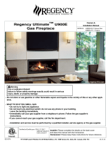
City Series
®
CB60E DIRECT VENT
Owners &
Installation Manual
STYLE MODEL
Three sided CB60E-NG / CB60E-LP
Corner Conversion 686-927 / 686-928
Tested by:
www.regency-re.com
- Do not store or use gasoline or other flammable vapors and liquids in the vicinity of this or any other appliance.
- WHAT TO DO IF YOU SMELL GAS
• Do not try to light any appliance.
• Do not touch any electrical switch: do not use any phone in your building.
Leave the building immediately.
• Immediately call your gas supplier from a neighbour's phone. Follow the gas supplier's
instructions.
• If you cannot reach your gas supplier, call the fire department.
- Installation and service must be performed by a qualified installer, service agency or the gas supplier.
WARNING
FIRE OR EXPLOSION HAZARD
Failure to follow safety warnings exactly could result in serious
injury, death, or property damage.
920-164b FPI FIREPLACE PRODUCTS INTERNATIONAL LTD. 6988 Venture St., Delta, BC Canada, V4G 1H4 01.14.20

2 | City Series CB60E
This appliance may be installed in an aftermarket, permanently located, manufactured home
(USA only) or mobile home, where not prohibited by local codes.
This appliance is only for use with the type of gas indicated on the rating plate. This appli-
ance is not convertible for use with other gases, unless a certified kit is used.
To the New Owner:
Congratulations!
You are the owner of a state-of-the-art Gas Fireplace by REGENCY
®
. The City Series are hand crafted appliances and have
been designed to provide you with all the warmth and charm of a wood fireplace at the flick of a switch. The CB60E City
Series have been approved by Intertek for both safety and efficiency. As it also bears our own mark, it promises to provide
you with economy, comfort and security for many trouble free years to follow. Please take a moment now to acquaint
yourself with these instructions and the many features of your Regency
®
Fireplace.

City Series CB60E | 3
MANUFACTURED MOBILE HOME REQUIREMENTS
INFORMATION FOR MOBILE/MANUFACTURED HOMES AFTER FIRST SALE
This Regency
®
product has been tested and listed by Intertek as a Direct Vent Wall Furnace to the following standards: to Vented Gas
Fireplace Heaters ANSI Z21.88-2017 • CSA 2.33-2017 and Gas-fired Appliances for Use at High Altitudes CSA 2.17-2017.
This Direct Vent System Appliance must be installed in accordance with the manufacturer's installation instructions and the Manufactured
Home Construction and Safety Standard, Title 24 CFR, Part 3280, or the current Standard of Fire Safety Criteria for Manufactured Home
Installations, Sites, and Communities ANSI/NFPA 501A, and with CAN/CSA Z240-MH Mobile Home Standard in Canada.
This appliance installation must comply with the manufacturer's installation instructions and local codes, if any. In the absence of local codes
follow the current National Fuel Gas Code, ANSI Z223.1 and the current National Electrical Code ANSI/NFPA 70 in the U.S.A., and the
current CAN/CGA B149 Gas Installation Code and the current Canadian Electrical Code CSA C22.1 in Canada.
This Regency
®
mobile/manufactured home listed appliance comes factory equipped with four 1/4" diameter holes located near each corner
of the base. Fasten the fireplace in place using screw, inserted through the holes.
This appliance comes equipped with a dedicated #8 Ground Lug for attachment of the ground wire to the steel chassis as applicable to local
codes. See the "Wiring Diagram" section.
The appliance, when installed, must be electrically grounded in accordance with local codes or, in the absence of local codes, with the
National Electrical Code, ANSI/NFPA 70, or the Canadian Electrical Code, CSA C22.1.
This appliance may only be installed in an aftermarket permanently located, manufactured home (U.S.A only) or mobile home, where not
prohibited by local codes.
This appliance can only be used with the type of gas indicated on the rating plate. This appliance is not convertible for use with other cases,
unless a certified kit is used.
Ensure that structural members are not cut or weakened during installation.

4 | City Series CB60E
WARNING
CARBON MONOXIDE POISONING HAZARD
Failure to follow the steps outlined below for each appliance connected to the venting
system being placed into operation could result in carbon monoxide poisoning or death.
The following steps shall be followed for each appliance connected to the venting system
being placed into operation, while all other appliances connected to the venting system are
not in operation:
1. Seal any unused openings in the venting system.
2. Inspect the venting system for proper size and horizontal pitch, as required in the
National Fuel Gas Code, ANSI Z223.1/NFPA 54 or the Natural Gas and Propane
Installation Code, CSA B149.1 and these instructions. Determine that there is no
blockage or restriction, leakage, corrosion and other deficiencies which could cause an
unsafe condition.
3. As far as practical, close all building doors and windows and all doors between the
space in which the appliance(s) connected to the venting system are located and other
spaces of the building.
4. Close fireplace dampers.
5. Turn on clothes dryers and any appliance not connected to the venting system. Turn on
any exhaust fans, such as range hoods and bathroom exhausts, so they are operating at
maximum speed. Do not operate a summer exhaust fan.
6. Follow the lighting instructions. Place the appliance being inspected into operation.
Adjust the thermostat so appliance is operating continuously.
7. Test for spillage from draft hood equipped appliances at the draft hood relief opening
after 5 minutes of main burner operation. Use the flame of a match or candle.
8. If improper venting is observed during any of the above tests, the venting system must
be corrected in accordance with National Fuel Gas Code, ANSI Z223.1/NFPA and/or
Natural Gas and Propane Installation Code, CSA B149.1.
9. After it has been determined that each appliance connected to the venting system
properly vents when tested as outlined above, return doors, windows, exhaust fans,
fireplace damper and any other gas-fired burning appliance to the previous
conditions of use.

City Series CB60E | 5
table of contents
Typical Installations ......................................................49
Maximum TV Recess ...............................................49
Flush TV with Hearth ...............................................49
Finishing ......................................................................50
Chase Venting .............................................................51
Wall Mount On / Off Switch and Battery
Holder Installation ........................................................52
Exterior Vent Termination Locations ............................53
5"x 8" Rigid Pipe Cross Reference Chart ....................54
Vent Restrictor Position ...............................................56
Horizontal Terminations - Flex Vent 5" x 8" ..................57
Venting Introduction .....................................................58
Venting Arrangement for Horizontal Terminations .......58
Horizontal Terminations - Rigid Pipe 5" x 8" ................59
Vertical Terminations - Rigid Pipe 5" x 8" ....................61
Venting Arrangement for Vertical Terminations ............62
Wiring the Unit .............................................................63
Wiring Diagram ............................................................64
System Data ................................................................65
High Elevation ..............................................................65
Gas Line Installation ....................................................65
Pilot Adjustment ...........................................................65
Gas Pipe Pressure Testing ..........................................65
885 S.I.T. Valve Description .........................................65
Inner Glass Panel Installation / Removal .....................66
Glass Barrier Installation .............................................68
Glass Barrier Adjustment.............................................69
Optional Barrier Glass Stoppers
Installation/Removal ....................................................70
LP Conversion Instructions ..........................................71
Bulb Replacement .......................................................73
Inner Black Panel Installation ......................................74
Outer Panels ................................................................74
Inner Black Enamel Panel Installation .........................76
Inner Black Glass Panel Installation ............................78
Burner and Firebox Media Options ..............................80
Optional Driftwood Log Set Installation .......................81
Optional Split Wood Log Set Installation .....................84
Optional Birch Wood Log Set Installation ....................87
Aeration Adjustment ....................................................91
Minimum Air Shutter Opening .....................................91
Copy of Safety Decal .....................................................6
Dimensions - Bay Install ................................................7
Dimensions - Corner Install ...........................................8
Important Message ......................................................9
Before You Start .............................................................9
First Fire ......................................................................10
Normal Operating Sounds Of Gas Appliances ............10
Lighting Procedure ......................................................11
Shutdown Procedure ...................................................11
Copy of the Lighting Plate Instructions ........................12
Proflame II Remote Control Operating Instructions .....13
Front & Side Glass Barrier Removal ............................17
Glass Barrier Adjustment.............................................18
Inner Glass Panel Installation/Removal .......................19
Inner Glass Panel Installation / Removal
- Side Glass ................................................................21
Optional Front Barrier Glass Stoppers Installation ......22
Bulb Replacement .......................................................23
Maintenance Instructions ............................................24
Log Replacement ........................................................24
Glass ...........................................................................24
Glass Replacement .....................................................24
General Safety Information ..........................................26
Installation Checklist ....................................................26
Locating Your Gas Fireplace - Bay Install ....................27
Locating Your Gas Fireplace - Corner Install ...............27
Installer's information
Owner's information
Unit Assembly Prior to Installation ...............................28
Clearances (3-sided) ...................................................30
Clearances ..................................................................31
Clearances - Corner Install ..........................................32
Mantel Clearances .......................................................33
Mantel Leg Clearances ................................................33
Framing Dimensions - Bay Install ................................34
Framing Dimensions Corner Kit - Corner Install
(Right Corner) ..............................................................35
Framing Dimensions Corner Kit - Corner Install
(Left Corner) ................................................................36
Corner Installation Kit (Black)
Assembly Steps ...........................................................37
Optional Framing Kit ....................................................40
Gas Connection - Back of Unit ....................................43
Gas Connection - Bottom of Unit .................................43
Gas Connection - Side of Unit .....................................43
Electrical Connection - Bottom of Unit .........................44
Electrical Connection - Side of Unit .............................44
Chase Vent Installation (White Front) ..........................45
Wall Board/Drywall Installation ....................................46
No Screw Zones ..........................................................46
Framing and Finishing Inset Installations ....................47
Typical Installations ......................................................48
Flush Install .............................................................48
Recessed Install ......................................................48
Installation
Maintenance Instructions ............................................92
Flame Pattern ..............................................................92
Log Replacement ........................................................92
Glass Gasket ...............................................................92
Glass ...........................................................................92
Glass Replacement .....................................................92
Valve Replacement ......................................................93
CB60E Main Assembly ................................................94
Warranty ......................................................................97
Maintenance

6 | City Series CB60E
safety decal
Part #: 920-166 - Side A
Colours: Black on white, except for parts indicated as being Red.
Punch out .25" hole top right corner where indicated.
Size: 100%
W- 6.27" x L- 9.18"
OCt. 23/19: Created decal
Material: Printable white polyester 7mm
Start serial sequence @ 000001
NOTE: This is a double sided decal
Part #: 920-166 - Side B
Colours: Black on white, except for parts indicated as being Red.
Punch out .25" hole top right corner where indicated.
Size: 100%
w- 6.52"
h- 11.13"
Oct. 23/19: Created decal
Part #: 920-165
Colour: Black on grey except what is indicated as being printed red.
Size: (File at 100%) 9.11"w x 6.27"h
Material:
Start serial sequence at 535000001
Oct. 23/19: Created draft
DO NOT REMOVE THIS LABEL / NE PAS ENLEVER CETTE ÉTIQUETTE
535
535
DOOR SEAL: Please
check that the door is
properly sealed
FPI Fireplace Products International Ltd. Delta, BC, Canada
Minimum Clearances to Combustibles /
Dégagement minimaux par rapport aux matériaux combustibles
Serial No./ No de série
MAY BE INSTALLED IN MANUFACTURED (MOBILE) HOMES AFTER FIRST SALE.
Listed/Nom: VENTED GAS FIREPLACE HEATER / FOYER AU GAZ À ÉVACUATION
Certified to / Certifi :é
ANSI Z21.88-2017 • CSA-2.33-2017
CSA 2.17-2017
Electrical supply / Alimentation électrique 115VAC, 2.5A, 60Hz.
Made in Canada/ Fabriqué au Canada
Duplicate S/N
(See instruction manual for detailed instructions)
(Voir manuel pour plus de détails)
GAZ PROPANE : Modèle CB60E-LP
PROPANE GAS: Model: CB60E-LP
Minimum supply pressure
Manifold pressure - High
Manifold pressure - Low
Orifice size
Maximum input
Minimum input
Altitude
GAZ NATUREL : Modèle CB60E-NG
5.0" WC/C.E. (1.25 kPa)
3.8" WC/C.E. (0.94 kPa)
1.1" WC/C.E. (0.27 kPa)
# 32 DMS
39,000 Btu/h (11.42 kW)
21,000 Btu/h (6.15 kW)
0-4500 ft/pi (0-1372 m)
11" WC/C.E. (2.73 kpa)
10.5" WC/C.E. (2.62 kPa)
2.9" WC/C.E. (0.72 kPa)
# 50 DMS
36,000 Btu/h (10.54 kW)
19,500 Btu/h (5.71 kW)
0-4500 ft/pi (0-1372 m)
Minimum supply pressure
Manifold pressure - High
Manifold pressure - Low
Orifice size
Maximum input
Minimum input
Altitude
Side Walls / Murs latéraux
A 5-7/8" (149 mm)
Ceiling / Plafond
B 81-1/4" (2064 mm)
Min. Mantel Height /Hteur Min
Manteau
C 9" (229 mm) with 12" mantel
Max. Mantel Depth/Profondeur Max
Manteau
D 12" (305 mm)
Alcove Width/Largeur Alcôve
E 119-1/2" (3035 mm)
Alcove Depth/Profondeur Alcôve
F 35" (889 mm)
This appliance must be installed in accordance with local codes, if any; if none, follow the National Fuel Gas Code, ANSI Z223.1, or Natural Gas and Propane Installation Code, CSA B149.1.
This appliance must be installed in accordance with the Standard CAN/CSA Z240 MH, Mobile Housing, in Canada, or with the Manufactured Home Construction and Safety Standard, Title 24 CFR, Part 3280, in the
United States, or when such a standard is not applicable, ANSI/NCSBCS A225.1/NFPA 501A, Manufactured Home Installations Standard.
This appliance is only for use with the type(s) of gas indicated on the rating plate and may be installed in an aftermarket, permanently located, manufactured home (USA only) or mobile home, where not prohibited by
local codes. See owner's manual for details. This appliance is supplied with a conversion kit.
L'appareil doit être installé conformément aux codes et règlements locaux, ou, en l'absence de tels règlements, selon les codes d'installation National Fuel Gas Code ANSI Z223.1, ou CSA-B149.1 Natural Gas and
Propane Installation Code en vigueur.
L'appareil doit être installé conformément à la norme CAN/CSA-Z240, Série MM, Maisons mobiles, ou la norme 24 CFR Part 3280, Manufactured Home Construction and Safety Standard. Si ces normes ne sont pas
applicables, veuillez vous référer à la norme ANSI/NCSBCS A225.1/NFPA 501A.
Cet appareil doit être utilisé uniquement avec les types de gaz indiqués sur la plaque signalétique et peut être installé dans une maison préfabriquée (É.-U. seulement) ou mobile installée à demeure si les règlements
locaux le permettent. Voir la notice de l'utilisateur pour plus de renseignements. Une trousse de conversion est fournie avec cet appareil.
C # 4001172
For Use Only with Barriers CB60E (Part #940-509/P, #940-510/P, #940-511/P) Follow installation instructions.
Utiliser uniquement avec l’écrans CB60E (n° 940-509/P, n° 940-510/P, n° 940-511/P) Suivre les instructions d'installation.
Pression d'alimentation minimale
Pression de sortie (manifold) - Haute
Pression de sortie (manifold) -
Basse
Taille de l’orifice
D bit calorifique maximalé
D bit calorifique minimalé
Altitude
Pression d'alimentation minimale
Pression de sortie (manifold) - Haute
Pression de sortie (manifold) - Basse
Taille de l’orifice
D bit calorifique maximalé
D bit calorifique minimalé
Altitude
VENTED GAS FIREPLACE HEATER - NOT FOR USE WITH SOLID FUELS.
NE PAS UTILISER AVEC UN COMBUSTIBLE SOLIDE. FOYER AU GAZ À ÉVACUATION -
Part No. 946-556 Heatwave Kit may be used. Le système Heatwave (pièce n°946-556) peut être utilisé.
Model/Modèle :
CB60E-NG
CB60E-LP
FOR USE WITH GLASS DOORS CERTIFIED WITH THE APPLIANCE ONLY DOIT ÊTRE UTILISÉ UNIQUEMENT AVEC LES PORTES VITRÉES CERTIFIÉES
2
Min. 180 in
Refer to Intertek's Directory of Building Products for detailed information.
Pour plus de détails , se reporter au Répertoire des produits de construction de Intertek.
D
E
F
A
B
C
This vented gas fireplace heater is not for use with air filters.
Ne pas utiliser de filtre à air avec ce foyer au gaz à évacuation.
920-166
CSA P.4.1 Fireplace Efficiency (FE) /Efficacité énergétique des foyers (EEF) CSA P.4.1
Natural Gas / Gaz naturel 56.23%
Propane Gas / Gaz propane 56.43%
CANADIAN ENERGY
PERFORMANCE
VERIFIED
RENDEMENT
ÉNERGÉTIQUE
VÉRIFIÉ
EP5011169
NATURAL GAS: Model: CB60E-NG
920-166
3DUWD
&RORXUV%ODFNRQ*UH\H[FHSWIRUSDUWVLQGLFDWHGDVEHLQJ5HG
3XQFKRXWKROHWRSULJKWFRUQHUZKHUHLQGLFDWHG
6L]H
Z
K
$SU&UHDWHGGHFDO
$SU$GGHG)U+HDGHUVZDUQLQJV
6HSW0DGHFKDQJHVWRWH[WSHU0DWWKHZ&KHQJ
'21275(029(7+,6,16758&7,213/$7(
1(3$6(1/(9(5&(77(e7,48(77('¶,16758&7,216
7278512))*$6$33/,$1&(3285e7(,1'5(81$33$5(,/$8*$=
7KLVDSSOLDQFHPXVWEHLQVWDOOHGLQDFFRUGDQFHZLWKORFDOFRGHVLIDQ\LIQRQHIROORZWKH1DWLRQDO)XHO*DV&RGH$16,=1)3$
RU1DWXUDO*DVDQG3URSDQH,QVWDOODWLRQ&RGHV&6$%
&HWDSSDUHLOGRLWrWUHLQVWDOOpFRQIRUPpPHQWDX[FRGHVORFDX[V¶LO\DOLHX(QO¶DEVHQFHGHWHOVFRGHVVXLYUHOH1DWLRQDO)XHO*DV&RGH
$16,=1)3$RXOHV1DWXUDO*DVDQG3URSDQH,QVWDOODWLRQ&RGHV&6$%
&$87,21+RWZKLOHLQRSHUDWLRQ'RQRWWRXFK6HYHUHEXUQVPD\UHVXOW'XHWRKLJKVXUIDFHWHPSHUDWXUHVNHHS
FKLOGUHQFORWKLQJDQGIXUQLWXUHJDVROLQHDQGRWKHUOLTXLGVKDYLQJÀDPPDEOHYDSRUVDZD\.HHSEXUQHUDQGFRQWURO
FRPSDUWPHQWFOHDQ6HHLQVWDOODWLRQDQGRSHUDWLQJLQVWUXFWLRQVDFFRPSDQ\LQJDSSOLDQFH
$77(17,216XUIDFHVFKDXGHVORUVTXHO¶DSSDUHLOHVWHQPDUFKH1HSDVWRXFKHU5LVTXHGHEUOXUHVJUDYHV(QUDLVRQ
GHVWHPSpUDWXUHVpOHYpHVOHVHQIDQWVOHVYrWHPHQWVHWOHPRELOLHUOH FDUEXUDQWHWWRXWDXWUH OLTXLGHDX[YDSHXUV
LQÀDPPDEOHV GRLYHQW rWUH WHQXV pORLJQpV GH O¶DSSDUHLO 1HWWR\HU UpJXOLqUHPHQW OH EUOHXU HW OH FRPSDUWLPHQW GHV
FRPPDQGHV9RLUOHVFRQVLJQHVG¶LQVWDOODWLRQHWG¶XWLOLVDWLRQIRXUQLHVDYHFO¶DSSDUHLO
/,*+7,1*,16758&7,216&216,*1(6'¶$//80$*(
)25<2856$)(7<5($'%()25(/,*+7,1*
32859275(6e&85,7e±¬/,5($9$17/$0,6((10$5&+(
:$51,1*,I\RXGRQRWIROORZWKHVHLQVWUXFWLRQVH[DFWO\DILUHRUH[SORVLRQPD\UHVXOWFDXVLQJSURSHUW\GDPDJH
SHUVRQDO LQMXU\ RU ORVVRI OLIH,PSURSHU LQVWDOODWLRQ DGMXVWPHQWDOWHUDWLRQ VHUYLFHRU PDLQWHQDQFH FDQFDXVH
LQMXU\RUSURSHUW\GDPDJH5HIHUWRWKHRZQHU¶VLQIRUPDWLRQPDQXDOSURYLGHGZLWKWKLVDSSOLDQFH)RUDVVLVWDQFH
RUDGGLWLRQDOLQIRUPDWLRQFRQVXOWDTXDOLILHGLQVWDOOHUVHUYLFHDJHQF\RUJDVVXSSOLHU
$9(57,66(0(174XLFRQTXHQHUHVSHFWHSDVVFUXSXOHXVHPHQWOHVLQVWUXFWLRQVGHODSUpVHQWHQRWLFHULVTXHG HGpFOHQFKHU
XQLQFHQGLHRXXQHH[SORVLRQSRXYDQWHQWUDvQHUGHVGpJkWVPDWpULHOVRXGHVEOHVVXUHVSRXYDQWrWUHPRUWHOOHV
7RXWGpIDXWGLQVWDOODWLRQGHUpJODJHGHPRGL¿FDWLRQGHVHUYLFHRXGHQWUHWLHQSHXWHQWUDvQHUGHVEOHVVXUHVRXGHVGRP
PDJHVPDWpULHOV5HSRUWH]YRXVDXPDQXHOGXWLOLVDWLRQIRXUQLDYHFFHWpTXLSHPHQW3RXUREWHQLUGHODLGHRXGHVLQIRU
PDWLRQVFRPSOpPHQWDLUHVFRQVXOWHUXQLQVWDOODWHXURXXQVHUYLFHGHQWUHWLHQTXDOL¿pRXOHIRXUQLVVHXUGHJD]
$7KLVDSSOLDQFHLVHTXLSSHGZLWKDQLJQLWLRQGHYLFHZKLFKDXWRPDWLFDOO\OLJKWVWKHSLORW
'RQRWWU\WROLJKWWKHSLORWE\KDQG
%%()25(23(5$7,1*VPHOODOODURXQGWKHDSSOLDQFHDUHDIRUJDV%HVXUHWRVPHOOQH[WWRWKHÀRRU
EHFDXVHVRPHJDVLVKHDYLHUWKDQDLUDQGZLOOVHWWOHRQWKHÀRRU
:+$772'2,)<2860(//*$6
'RQRWWU\WROLJKWDQ\DSSOLDQFH
'RQRWWRXFKDQ\HOHFWULFVZLWFKGRQRWXVHDQ\SKRQHLQ\RXUEXLOGLQJ
,PPHGLDWHO\FDOO\RXUJDVVXSSOLHUIURPDQHLJKERXUVSKRQH)ROORZWKHJDVVXSSOLHU¶VLQVWUXFWLRQV
,I\RXFDQQRWUHDFK\RXUJDVVXSSOLHUFDOOWKH¿UHGHSDUWPHQW
& 'RQRWXVHWKLVDSSOLDQFHLIDQ\SDUWKDVEHHQXQGHUZDWHU,PPHGLDWHO\FDOODTXDOL¿HGVHUYLFH
WHFKQLFLDQWRLQVSHFWWKHDSSOLDQFHDQGUHSODFHDQ\SDUWRIWKHFRQWUROV\VWHPDQGDQ\
JDVFRQWUROZKLFKKDVEHHQXQGHUZDWHU
' ,IWKHJDVYDOYHUHTXLUHVUHSDLUFDOODTXDOL¿HGVHUYLFHWHFKQLFLDQ)RUFHRUDWWHPSWHGUHSDLUPD\UHVXOWLQD¿UHRUH[SORVLRQ
$ &HWDSSDUHLOHVWPXQLG¶XQGLVSRVLWLIG¶DOOXPDJHTXLDOOXPHDXWRPDWLTXHPHQWODYHLOOHXVH
1HWHQWH]SDVG¶DOOXPHUODYHLOOHXVHPDQXHOOHPHQW
%$9$17/$0,6((10$5&+(UHQLÀH]WRXWDXWRXUGHO¶DSSDUHLOSRXUGpFHOHUXQHRGHXUGHJD]5HQLÀH]DXQLYHDXGXSODQFKHUFDUFHUWDLQVJD]
VRQWSOXVORXUGVTXHO¶DLUHWSHXYHQWV¶DFFXPXOHUDXQLYHDXGXVRO
48()$,5(6,92866(17(=81(2'(85'(*$=
1HWHQWH]SDVG¶DOOXPHUO¶DSSDUHLO
1HWRXFKH]jDXFXQLQWHUUXSWHXUQXWLOLVH]SDVGHWpOpSKRQHVVHWURXYDQWGDQVOHEkWLPHQW
$SSHOH]LPPpGLDWHPHQWYRWUHIRXUQLVVHXUGHJD]GHSXLVXQWpOpSKRQHH[WpULHXU6XLYH]OHVLQVWUXFWLRQVGXIRXUQLVVHXU
6LYRXVQHSRXYH]SDVUHMRLQGUHOHIRXUQLVVHXUDSSHOH]OHVHUYLFHLQFHQGLH
& 1¶XWLOLVH]SDVFHWDSSDUHLOV¶LODpWpSORQJpGDQVO¶HDXPrPHSDUWLHOOHPHQW)DLWHVLQVSHFWHUO¶DSSDUHLOSDUXQWHFKQLFLHQTXDOL¿pHWUHPSODFH]WRXW
pOpPHQWGXV\VWqPHGHFRQWU{OHRXGHFRPPDQGHTXLDpWpSORQJpGDQVO¶HDX
'6LOHURELQHWGHJD]H[LJHGHVUpSDUDWLRQVFRQWDFWHUXQWHFKQLFLHQGHVHUYLFHTXDOL¿p4XLFRQTXHWHQWHGHIRUFHUODPDQHWWHRXGHODUpSDUHUSHXW
SURYRTXHUXQHH[SORVLRQRXXQLQFHQGLH
$55Ç7(=/LVH]OHVLQVWUXFWLRQVGHVpFXULWpVXUODSRUWLRQVXSpULHXUHGHFHWWHpWLTXHWWH
&HWDSSDUHLOHVWPXQLGXQGLVSRVLWLIGDOOXPDJHIRQFWLRQQDQWVXUGHPDQGHTXLVpWHLQWDSUqVVHSWMRXUV
6¶DVVXUHUTXHOHFRPPXWDWHXUSULQFLSDOHVWHQSRVLWLRQ21HWRXTXHOHEORFSLOHVPXUDOOHFDVpFKpDQWHVWHQSRVLWLRQ5(027(!
$SSX\HUVXUODWRXFKH212))GHODWpOpFRPPDQGHSXLVUHOkFKHU8QELSVRQRUHUHWHQWLUDGHSXLVOHUpFHSWHXU6LYRXVQXWLOLVH]SDVOD
WpOpFRPPDQGHODSSDUHLOSHXWpJDOHPHQWrWUHDOOXPpHQIDLVDQWJOLVVHUOHFRPPXWDWHXUGXEORFSLOHVVXUODSRVLWLRQ21!OHFDVpFKp
DQW
$SUqVHQYLURQVHFRQGHVOHV\VWqPHGDOOXPDJHSURGXLUDXQHpWLQFHOOHSHQGDQWVHFRQGHVSRXUDOOXPHUOHEUOHXUSULQFLSDO
/DSSDUHLOV¶DOOXPHUD
5HPDUTXH$XSUHPLHUDOOXPDJHOHV\VWqPHWHQWHG¶DOOXPHUOHVÀDPPHVSHQGDQWVHFRQGHV6LO¶HVVDLHVWLQIUXFWXHX[OHV\VWqPH
IHUDXQHSDXVHGHVHFRQGHV&¶HVWFHTXRQDSSHOOHOpWDSHGHUHFWL¿FDWLRQ&HGpODLpFRXOpOHV\VWqPHWHQWHjQRXYHDXGDOOXPHUOHV
ÀDPPHVHQSURGXLVDQWGHVpWLQFHOOHVSHQGDQWVHFRQGHV6LOHVÀDPPHVQHV¶DOOXPHQWWRXMRXUVSDVOHV\VWqPHVHPHWHQPRGHYHU
URXLOODJH
,OIDXWDORUVOHUpLQLWLDOLVHUHQVXLYDQWOHVpWDSHVFLGHVVRXVSRXUOHGpYHUURXLOOHU
D $WWHQGUHPLQXWHVHWpWHLQGUHO¶DSSDUHLOHQDSSX\DQWVXUODWRXFKH212))GHODWpOpFRPPDQGH
E $WWHQGUHVHFRQGHVHWDSSX\HUHQFRUHXQHIRLVVXUODWRXFKH212))
F/DSSDUHLOUpSqWHUDOpWDSH
6LODSSDUHLOQHIRQFWLRQQHSDVVXLYH]OHVLQVWUXFWLRQV3RXUpWHLQGUHODSSDUHLODXJD]HWDSSHOH]XQWHFKQLFLHQTXDOL¿pRXYRWUH
IRXUQLVVHXUGHJD]
67235HDGWKHVDIHW\LQIRUPDWLRQDERYHRQWKLVODEHO
7KLVDSSOLDQFHLVHTXLSSHGZLWKDQRQGHPDQGSLORWWKDWVKXWVRႇDIWHUVHYHQGD\V
(QVXUHWKH0DLQVZLWFKLVLQWKH21SRVLWLRQDQGRUWKHZDOOPRXQWHGEDWWHU\KROGHULIHTXLSSHGLVLQWKH5(027(!SRVLWLRQ
3UHVVDQGUHOHDVHWKH212))EXWWRQRQWKHUHPRWHKDQGKHOGWUDQVPLWWHU$QDXGLEOHEHHSVKRXOGEHKHDUGIURPWKHUHFHLYHU,IQRW
XVLQJWKHUHPRWHWKHXQLWFDQDOVREHWXUQHGRQE\VOLGLQJWKHEDWWHU\KROGHUVZLWFKWRWKH21!SRVLWLRQLIHTXLSSHG
$IWHUDSSUR[LPDWHO\VHFRQGVWKHVSDUNLJQLWLRQV\VWHPZLOOVSDUNIRUVHFRQGVWROLJKWWKHPDLQEXUQHU
7KHXQLWZLOOWXUQRQ
1RWH7KH¿UVWDWWHPSWWRLJQLWLRQZLOOODVWDSSUR[LPDWHO\VHFRQGV,IWKHUHLVQRÀDPHLJQLWLRQUHFWL¿FDWLRQWKHERDUGZLOOVWRSVSDUN
LQJIRUDSSUR[LPDWHO\VHFRQGV$IWHUWKLVZDLWWLPHWKHERDUGZLOOVWDUWDVHFRQGWU\IRULJQLWLRQE\VSDUNLQJIRUDSSUR[LPDWHO\
VHFRQGV,IWKHUHLVVWLOOQRSRVLWLYHLJQLWLRQDIWHUWKHVHFRQGDWWHPSWWKHERDUGZLOOJRLQWRORFNRXW
7KHV\VWHPZLOOQHHGWREHUHVHWDVIROORZVDIWHUJRLQJLQWRORFNRXWPRGH
D :DLWPLQXWHVWXUQWKHV\VWHPRႇE\SUHVVLQJWKH212))EXWWRQRQWKHUHPRWH
E $IWHUDSSUR[LPDWHO\VHFRQGVSUHVVWKH212))EXWWRQDJDLQ
F 8QLWZLOOUHSHDWVWHS
,IWKHDSSOLDQFHZLOOQRWRSHUDWHIROORZWKHLQVWUXFWLRQV7R7XUQ2ႇ*DV$SSOLDQFHDQGFDOO\RXUVHUYLFHWHFKQLFLDQRUJDVVXSSOLHU
1) Press the ON/OFF button on the remote or slide the wall mount switch to the "OFF" position.
2) If service is to be performed–you must disconnect power and shut off gas to the unit.
Appuyer sur la touche ON/OFF de la télécommande ou faites glisser l'interrupteur mural sur la position "OFF".
/RUVGHOHQWUHWLHQGHODSSDUHLOYRXVGHYH]GpEUDQFKHUODOLPHQWDWLRQpOHFWULTXHHWFRXSHUOHJD]DOLPHQWDQWODSSDUHLO
This is a copy of the label that accompanies Direct Vent Gas Fireplace. We have printed a copy of the
contents here for your review. The safety label is located on the front inside base of the unit, visible when
the outer front panel is removed.
NOTE: Regency
®
units are constantly being improved. Check the label on the unit and if there is a
difference, the label on the unit is the correct one.
Copy of Safety Decal
For the State of Massachusetts, installation
and repair must be done by a plumber or
gas fitter licensed in the Commonwealth of
Massachusetts.
For the State of Massachusetts, flexible con-
nectors shall not exceed 36 inches in length.
For the State of Massachusetts, the appli-
ances individual manual shut-off must be a
t-handle type valve.
The State of Massachusetts requires the
installation of a carbon monoxide alarm in
accordance with NFPA 720 and a CO alarm
with battery back up in the same room where
the gas appliance is installed.

City Series CB60E | 7
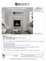
dimensions
71
1
4
"
1810 mm
11"
279 mm
18"
466 mm
10
1
4
"
260 mm
35
5
8
"
905 mm
72
5
16
"
1837 mm
35
5
8
"
905 mm
8"
204 mm
5"
127 mm
13"
330 mm
7
1
4
"
185 mm
20
5
16
"
515 mm
39"
990 mm
16" (406mm)
Dimensions - Bay Install
Note: Height Dimension is taken with leveling legs fully inserted and may vary depending on the height of the leveling legs, when unscrewed or extended.
Dimensions will appear as (inches)" / (metric) mm
throughout this manual. The inches are rounded to the
nearest 1/16" when converted, when greater accuracy
is required, use the metric dimensions.
Note: These units are non-load bearing.
ALL PICTURES / DIAGRAMS SHOWN THROUGHOUT THIS MANUAL ARE FOR ILLUSTRATION PURPOSES ONLY.
ACTUAL PRODUCT MAY VARY DUE TO PRODUCT ENHANCEMENTS.

8 | City Series CB60E
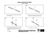
dimensions
71
1
4
"
1810 mm
11"
279 mm
18"
466 mm
10
1
4
"
263 mm
35
5
8
"
905 mm
72
5
16
"
1837 mm
35
5
8
"
905 mm
8"
204 mm
5"
127 mm
13"
330 mm
7
1
4
"
185 mm
20
5
16
"
515 mm
39"
990 mm
16
9
16
"
421 mm
Dimensions - Corner Install
Note: Height Dimension is taken with leveling legs fully inserted and may vary depending on the height of the leveling legs, when unscrewed or extended.
Dimensions will appear as (inches)" / (metric) mm
throughout this manual. The inches are rounded to the
nearest 1/16" when converted, when greater accuracy
is required, use the metric dimensions.
Note: These units are non-load bearing.
ALL PICTURES / DIAGRAMS SHOWN THROUGHOUT THIS MANUAL ARE FOR ILLUSTRATION PURPOSES ONLY.
ACTUAL PRODUCT MAY VARY DUE TO PRODUCT ENHANCEMENTS.

City Series CB60E | 9
owner's information
CLOTHING OR OTHER FLAMMABLE
MATERIAL SHOULD NOT BE PLACED
ON OR NEAR THE APPLIANCE.
CHILDREN AND ADULTS SHOULD BE
ALERTED TO THE HAZARDS OF HIGH
SURFACE TEMPERATURES, ESPE-
CIALLY THE FIREPLACE GLASS, AND
SHOULD STAY AWAY TO AVOID BURNS
OR CLOTHING IGNITION.
INSTALLATION AND REPAIR SHOULD
BE DONE BY AN AUTHORIZED
SERVICE PERSON. THE APPLIANCE
SHOULD BE INSPECTED BEFORE
USE AND AT LEAST ANNUALLY BY A
PROFESSIONAL SERVICE PERSON.
MORE FREQUENT CLEANING MAY
BE REQUIRED DUE TO EXCESSIVE
LINT FROM CARPETING, BEDDING
MATERIAL, ETC. IT IS IMPERATIVE THAT
CONTROL COMPARTMENTS, BURNERS
AND CIRCULATING AIR PASSAGEWAYS
OF THE APPLIANCE BE KEPT CLEAN.
DUE TO HIGH TEMPERATURES, THE
APPLIANCE SHOULD BE LOCATED
OUT OF TRAFFIC AND AWAY FROM
FURNITURE AND DRAPERIES.
WARNING: FAILURE TO INSTALL THIS
APPLIANCE CORRECTLY WILL VOID
YOUR WARRANTY AND MAY CAUSE A
SERIOUS HOUSE FIRE.
YOUNG CHILDREN SHOULD BE CARE-
FULLY SUPERVISED WHEN THEY ARE
IN THE SAME AREA AS THE APPLIANCE.
TODDLERS, YOUNG CHILDREN AND
OTHERS MAY BE SUSCEPTIBLE TO AC-
CIDENTAL CONTACT BURNS. A PHYSI-
CAL BARRIERS IS RECOMMENDED IF
THERE ARE AT RISK INDIVIDUAL IN
THE HOUSE. TO RESTRICT ACCESS
TO A FIREPLACE OR STOVE, INSTALL
AN ADJUSTABLE SAFETY GATE TO
KEEP TODDLERS, YOUNG CHILDREN
AND OTHER AT RISK INDIVIDUALS OUT
OF THE ROOM AND AWAY FROM HOT
SURFACES.
Important Message
SAVE THESE INSTRUCTIONS
City Line Direct Vent Fireplaces must be installed
in accordance with these instructions. Carefully
read all the instructions in this manual first. Consult
the "authority having jurisdiction" to determine the
need for a permit prior to starting the installation.
It is the responsibility of the installer to ensure
this fireplace is installed in compliance with
manufacturer's instructions and all applicable codes.
Before You Start
Safe installation and operation of this appliance
requires common sense, however, we are required
by the Canadian Safety Standards and ANSI
Standards to make you aware of the following:
ANY SAFETY SCREEN, GUARD, OR
BARRIER REMOVED FOR SERVICING
THE APPLIANCE, MUST BE REPLACED
PRIOR TO OPERATING THE APPLIANCE.
IF THE BARRIER BECOMES DAMAGED,
THE BARRIER SHALL BE REPLACED
WITH THE MANUFACTURER'S BARRIER
FOR THIS APPLIANCE.
A BARRIER DESIGNED TO REDUCE
THE RISK OF BURNS FROM THE HOT
VIEWING GLASS IS PROVIDED WITH
THIS APPLIANCE AND SHALL BE
INSTALLED FOR THE PROTECTION
OF CHILDREN AND OTHER AT-RISK
INDIVIDUALS
WE RECOMMEND REMOVING THE
GLASS WITH THE GLASS VACUUM
HOLDERS SUPPLIED BY THE MANU-
FACTURER. LOWER THE GLASS TO
REST IN A SAFE PLACE. THIS IS TO
PREVENT DAMAGE TO THE GLASS
EDGES. EXTRA CARE MUST BE TAKEN
WHEN REMOVING/INSTALLING THE
GLASS. BREAKAGE OR DAMAGE TO
THE EDGE OF THE GLASS WHICH
OCCURS AS A RESULT OF CARELESS
HANDLING WILL NOT BE COVERED
UNDER WARRANTY.

10 | City Series CB60E
owner's information
Normal Operating Sounds Of Gas
Appliances
It is possible that you will hear some sounds from
your gas appliance. This is perfectly normal due to
the fact that there are various gauges and types of
steel used within your appliance. Listed below are
some examples. All are normal operating sounds
and should not be considered as defects in your
appliance.
Burner Tray:
The burner tray is positioned directly under the
burner tube(s) media and logs and is made of a
different gauge material from the rest of the firebox
and body. Therefore, the varying thicknesses of
steel will expand and contract at slightly different
rates which can cause "ticking" and "cracking"
sounds. You should also be aware that as there
are temperature changes within the unit these
sounds will likely re-occur. Again, this is normal
for steel fireboxes.
Pilot Flame:
While the pilot flame is on it can make a very slight
"whisper" sound.
Gas Control Valve:
As the gas control valve turns ON and OFF, a
dull clicking sound may be audible, this is normal
operation of a gas regulator or valve.
Unit Body/Firebox:
Different types and thicknesses of steel will expand
and contract at different rates resulting in some
"cracking" and "ticking" sounds will be heard
throughout the cycling process.
During the first few fires, a white film may develop
on the glass front as part of the curing process.
The glass should be cleaned after the unit has
cooled down or the film will bake on and become
very difficult to remove. Use a non-abrasive
cleaner and DO NOT ATTEMPT TO CLEAN THE
GLASS WHILE IT IS HOT.
The FIRST FIRE in your fireplace is part of the paint
curing process. To ensure the paint is properly cured,
it is recommended you burn your fireplace for at
least four (4) hours the first time.
When first operated, the unit will release an odour
caused by the curing of the paint and the burning
off of any oils remaining from manufacturing. Smoke
detectors in the house may go off at this time. Open
a few windows to ventilate the room for a couple of
hours. The glass may require cleaning.
NOTE: When the glass is cold and the appli-
ance is lit, it may cause condensation
and fog the glass. This condensation
is normal and will disappear in a few
minutes as the glass heats up.
DO NOT ATTEMPT TO CLEAN THE GLASS
WHILE IT IS STILL HOT!
DO NOT BURN THE UNIT WITHOUT THE
GLASS IN PLACE.
First Fire

City Series CB60E | 11
owner's information
* Not offered on all models.
IMPORTANT: The remote control system supplied with this appliance has
several options for starting/operating the appliance using the battery holder
and ON/OFF key on the hand held transmitter.
Prior to operating this appliance, please read the remote control operating
instructions (packaged with remote control) to understand how to operate
this remote control system.
1. Ensure the battery holder switch is in the Remote position and / or wall
mounted battery holder (if equipped) is in the <REMOTE> position.
2. Press and release the ON/OFF button on the remote handheld transmitter
(see Diagram 1). An audible beep should be heard from the receiver. If
not using the remote, the unit can also be turned on by sliding the battery
holder switch to the <ON> position (if equipped).
Note: The first try for ignition will last approximately 60 seconds. If there is no
flame ignition (rectification) the board will stop sparking for approximately
35 seconds. After wait time , the board will start second try for ignition by
sparking for approximately 60 seconds . If there is still no positive ignition
the board will go into lock out.
The system will need to be reset as follows:
a) Turn the system off by pressing the ON/OFF button on the remote.
b) Wait 5 minutes then repeat from step 2.
Shutdown Procedure
1. Press the ON/OFF button on the remote
2. If service is to be performed- you must disconnect power and shut off gas
to the unit.
ON/OFF
Button
Diagram 1
3. After approximately 15 seconds (for powervent models) the spark ignition
system will spark for 60 seconds to light the main burner.
4. The unit will turn on.
Lighting Procedure
Continuous Pilot/Intermittent Pilot (CPI/IPI) selection
See remote control instructions for details.
Note: Power vent models do not have a continuous pilot option.
*
* Actual transmitter is black as shown in Diagram 1.
*
*
*

12 | City Series CB60E
owner's information
Copy of the Lighting Plate Instructions
Part #: 920-166 - Side A
Colours: Black on white, except for parts indicated as being Red.
Punch out .25" hole top right corner where indicated.
Size: 100%
W- 6.27" x L- 9.18"
OCt. 23/19: Created decal
Material: Printable white polyester 7mm
Start serial sequence @ 000001
NOTE: This is a double sided decal
Part #: 920-166 - Side B
Colours: Black on white, except for parts indicated as being Red.
Punch out .25" hole top right corner where indicated.
Size: 100%
w- 6.52"
h- 11.13"
Oct. 23/19: Created decal
Part #: 920-165
Colour: Black on grey except what is indicated as being printed red.
Size: (File at 100%) 9.11"w x 6.27"h
Material:
Start serial sequence at 535000001
Oct. 23/19: Created draft
DO NOT REMOVE THIS LABEL / NE PAS ENLEVER CETTE ÉTIQUETTE
535
535
DOOR SEAL: Please
check that the door is
properly sealed
FPI Fireplace Products International Ltd. Delta, BC, Canada
Minimum Clearances to Combustibles /
Dégagement minimaux par rapport aux matériaux combustibles
Serial No./ No de série
MAY BE INSTALLED IN MANUFACTURED (MOBILE) HOMES AFTER FIRST SALE.
Listed/Nom: VENTED GAS FIREPLACE HEATER /
FOYER AU GAZ À ÉVACUATION
Certified to / Certifi :é ANSI Z21.88-2017 • CSA-2.33-2017
CSA 2.17-2017
Electrical supply / Alimentation électrique 115VAC, 2.5A, 60Hz.
Made in Canada/ Fabriqué au Canada
Duplicate S/N
(See instruction manual for detailed instructions)
(Voir manuel pour plus de détails)
GAZ PROPANE : Modèle CB60E-LP
PROPANE GAS: Model: CB60E-LP
Minimum supply pressure
Manifold pressure - High
Manifold pressure - Low
Orifice size
Maximum input
Minimum input
Altitude
GAZ NATUREL : Modèle CB60E-NG
5.0" WC/C.E. (1.25 kPa)
3.8" WC/C.E. (0.94 kPa)
1.1" WC/C.E. (0.27 kPa)
# 32 DMS
39,000 Btu/h (11.42 kW)
21,000 Btu/h (6.15 kW)
0-4500 ft/pi (0-1372 m)
11" WC/C.E. (2.73 kpa)
10.5" WC/C.E. (2.62 kPa)
2.9" WC/C.E. (0.72 kPa)
# 50 DMS
36,000 Btu/h (10.54 kW)
19,500 Btu/h (5.71 kW)
0-4500 ft/pi (0-1372 m)
Minimum supply pressure
Manifold pressure - High
Manifold pressure - Low
Orifice size
Maximum input
Minimum input
Altitude
Side Walls / Murs latéraux
A 5-7/8" (149 mm)
Ceiling / Plafond
B 81-1/4" (2064 mm)
Min. Mantel Height /Hteur Min
Manteau
C 9" (229 mm) with 12" mantel
Max. Mantel Depth/Profondeur Max
Manteau
D 12" (305 mm)
Alcove Width/Largeur Alcôve
E 119-1/2" (3035 mm)
Alcove Depth/Profondeur Alcôve
F 35" (889 mm)
This appliance must be installed in accordance with local codes, if any; if none, follow the National Fuel Gas Code, ANSI Z223.1, or Natural Gas and Propane Installation Code, CSA B149.1.
This appliance must be installed in accordance with the Standard CAN/CSA Z240 MH, Mobile Housing, in Canada, or with the Manufactured Home Construction and Safety Standard, Title 24 CFR, Part 3280, in the
United States, or when such a standard is not applicable, ANSI/NCSBCS A225.1/NFPA 501A, Manufactured Home Installations Standard.
This appliance is only for use with the type(s) of gas indicated on the rating plate and may be installed in an aftermarket, permanently located, manufactured home (USA only) or mobile home, where not prohibited by
local codes. See owner's manual for details. This appliance is supplied with a conversion kit.
L'appareil doit être installé conformément aux codes et règlements locaux, ou, en l'absence de tels règlements, selon les codes d'installation National Fuel Gas Code ANSI Z223.1, ou CSA-B149.1 Natural Gas and
Propane Installation Code en vigueur.
L'appareil doit être installé conformément à la norme CAN/CSA-Z240, Série MM, Maisons mobiles, ou la norme 24 CFR Part 3280, Manufactured Home Construction and Safety Standard. Si ces normes ne sont pas
applicables, veuillez vous référer à la norme ANSI/NCSBCS A225.1/NFPA 501A.
Cet appareil doit être utilisé uniquement avec les types de gaz indiqués sur la plaque signalétique et peut être installé dans une maison préfabriquée (É.-U. seulement) ou mobile installée à demeure si les règlements
locaux le permettent. Voir la notice de l'utilisateur pour plus de renseignements. Une trousse de conversion est fournie avec cet appareil.
C # 4001172
For Use Only with Barriers CB60E (Part #940-509/P, #940-510/P, #940-511/P) Follow installation instructions.
Utiliser uniquement avec l’écrans CB60E (n° 940-509/P, n° 940-510/P, n° 940-511/P) Suivre les instructions d'installation.
Pression d'alimentation minimale
Pression de sortie (manifold) - Haute
Pression de sortie (manifold) -
Basse
Taille de l’orifice
D bit calorifique maximalé
D bit calorifique minimalé
Altitude
Pression d'alimentation minimale
Pression de sortie (manifold) - Haute
Pression de sortie (manifold) - Basse
Taille de l’orifice
D bit calorifique maximalé
D bit calorifique minimalé
Altitude
VENTED GAS FIREPLACE HEATER - NOT FOR USE WITH SOLID FUELS.
NE PAS UTILISER AVEC UN COMBUSTIBLE SOLIDE. FOYER AU GAZ À ÉVACUATION -
Part No. 946-556 Heatwave Kit may be used. Le système Heatwave (pièce n°946-556) peut être utilisé.
Model/Modèle :
CB60E-NG
CB60E-LP
FOR USE WITH GLASS DOORS CERTIFIED WITH THE APPLIANCE ONLY DOIT ÊTRE UTILISÉ UNIQUEMENT AVEC LES PORTES VITRÉES CERTIFIÉES
2
Min. 180 in
Refer to Intertek's Directory of Building Products for detailed information.
Pour plus de détails , se reporter au Répertoire des produits de construction de Intertek.
D
E
F
A
B
C
This vented gas fireplace heater is not for use with air filters.
Ne pas utiliser de filtre à air avec ce foyer au gaz à évacuation.
920-166
CSA P.4.1 Fireplace Efficiency (FE) /
Efficacité énergétique des foyers (EEF) CSA P.4.1
Natural Gas / Gaz naturel 56.23%
Propane Gas / Gaz propane 56.43%
CANADIAN ENERGY
PERFORMANCE
VERIFIED
RENDEMENT
ÉNERGÉTIQUE
VÉRIFIÉ
EP5011169
NATURAL GAS: Model: CB60E-NG
920-166
3DUWD
&RORXUV%ODFNRQ*UH\H[FHSWIRUSDUWVLQGLFDWHGDVEHLQJ5HG
3XQFKRXWKROHWRSULJKWFRUQHUZKHUHLQGLFDWHG
6L]H
Z
K
$SU&UHDWHGGHFDO
$SU$GGHG)U+HDGHUVZDUQLQJV
6HSW0DGHFKDQJHVWRWH[WSHU0DWWKHZ&KHQJ
'21275(029(7+,6,16758&7,213/$7(
1(3$6(1/(9(5&(77(e7,48(77('¶,16758&7,216
7278512))*$6$33/,$1&(3285e7(,1'5(81$33$5(,/$8*$=
7KLVDSSOLDQFHPXVWEHLQVWDOOHGLQDFFRUGDQFHZLWKORFDOFRGHVLIDQ\LIQRQHIROORZWKH1DWLRQDO)XHO*DV&RGH$16,=1)3$
RU1DWXUDO*DVDQG3URSDQH,QVWDOODWLRQ&RGHV&6$%
&HWDSSDUHLOGRLWrWUHLQVWDOOpFRQIRUPpPHQWDX[FRGHVORFDX[V¶LO\DOLHX(QO¶DEVHQFHGHWHOVFRGHVVXLYUHOH1DWLRQDO)XHO*DV&RGH
$16,=1)3$RXOHV1DWXUDO*DVDQG3URSDQH,QVWDOODWLRQ&RGHV&6$%
&$87,21+RWZKLOHLQRSHUDWLRQ'RQRWWRXFK6HYHUHEXUQVPD\UHVXOW'XHWRKLJKVXUIDFHWHPSHUDWXUHVNHHS
FKLOGUHQFORWKLQJDQGIXUQLWXUHJDVROLQHDQGRWKHUOLTXLGVKDYLQJÀDPPDEOHYDSRUVDZD\.HHSEXUQHUDQGFRQWURO
FRPSDUWPHQWFOHDQ6HHLQVWDOODWLRQDQGRSHUDWLQJLQVWUXFWLRQVDFFRPSDQ\LQJDSSOLDQFH
$77(17,216XUIDFHVFKDXGHVORUVTXHO¶DSSDUHLOHVWHQPDUFKH1HSDVWRXFKHU5LVTXHGHEUOXUHVJUDYHV(QUDLVRQ
GHVWHPSpUDWXUHVpOHYpHVOHVHQIDQWVOHVYrWHPHQWVHWOHPRELOLHUOHFDUEXUDQW HWWRXW DXWUHOLTXLGHDX[YDSHXUV
LQÀDPPDEOHV GRLYHQW rWUH WHQXV pORLJQpV GH O¶DSSDUHLO 1HWWR\HU UpJXOLqUHPHQW OH EUOHXU HW OH FRPSDUWLPHQW GHV
FRPPDQGHV9RLUOHVFRQVLJQHVG¶LQVWDOODWLRQHWG¶XWLOLVDWLRQIRXUQLHVDYHFO¶DSSDUHLO
/,*+7,1*,16758&7,216&216,*1(6'¶$//80$*(
)25<2856$)(7<5($'%()25(/,*+7,1*
32859275(6e&85,7e±¬/,5($9$17/$0,6((10$5&+(
:$51,1*,I\RXGRQRWIROORZWKHVHLQVWUXFWLRQVH[DFWO\DILUHRUH[SORVLRQPD\UHVXOWFDXVLQJSURSHUW\GDPDJH
SHUVRQDO LQMXU\ RUORVV RI OLIH,PSURSHU LQVWDOODWLRQDGMXVWPHQWDOWHUDWLRQ VHUYLFHRU PDLQWHQDQFHFDQFDXVH
LQMXU\RUSURSHUW\GDPDJH5HIHUWRWKHRZQHU¶VLQIRUPDWLRQPDQXDOSURYLGHGZLWKWKLVDSSOLDQFH)RUDVVLVWDQFH
RUDGGLWLRQDOLQIRUPDWLRQFRQVXOWDTXDOLILHGLQVWDOOHUVHUYLFHDJHQF\RUJDVVXSSOLHU
$9(57,66(0(174XLFRQTXHQHUHVSHFWHSDVVFUXSXOHXVHPHQWOHVLQVWUXFWLRQVGHO DSUpVHQWHQ RWLFHULVTXHG HGpFOHQFKHU
XQLQFHQGLHRXXQHH[SORVLRQSRXYDQWHQWUDvQHUGHVGpJkWVPDWpULHOVRXGHVEOHVVXUHVSRXYDQWrWUHPRUWHOOHV
7RXWGpIDXWGLQVWDOODWLRQGHUpJODJHGHPRGL¿FDWLRQGHVHUYLFHRXGHQWUHWLHQSHXWHQWUDvQHUGHVEOHVVXUHVRXGHVGRP
PDJHVPDWpULHOV5HSRUWH]YRXVDXPDQXHOGXWLOLVDWLRQIRXUQLDYHFFHWpTXLSHPHQW3RXUREWHQLUGHODLGHRXGHVLQIRU
PDWLRQVFRPSOpPHQWDLUHVFRQVXOWHUXQLQVWDOODWHXURXXQVHUYLFHGHQWUHWLHQTXDOL¿pRXOHIRXUQLVVHXUGHJD]
$7KLVDSSOLDQFHLVHTXLSSHGZLWKDQLJQLWLRQGHYLFHZKLFKDXWRPDWLFDOO\OLJKWVWKHSLORW
'RQRWWU\WROLJKWWKHSLORWE\KDQG
%%()25(23(5$7,1*VPHOODOODURXQGWKHDSSOLDQFHDUHDIRUJDV%HVXUHWRVPHOOQH[WWRWKHÀRRU
EHFDXVHVRPHJDVLVKHDYLHUWKDQDLUDQGZLOOVHWWOHRQWKHÀRRU
:+$772'2,)<2860(//*$6
'RQRWWU\WROLJKWDQ\DSSOLDQFH
'RQRWWRXFKDQ\HOHFWULFVZLWFKGRQRWXVHDQ\SKRQHLQ\RXUEXLOGLQJ
,PPHGLDWHO\FDOO\RXUJDVVXSSOLHUIURPDQHLJKERXUVSKRQH)ROORZWKHJDVVXSSOLHU¶VLQVWUXFWLRQV
,I\RXFDQQRWUHDFK\RXUJDVVXSSOLHUFDOOWKH¿UHGHSDUWPHQW
& 'RQRWXVHWKLVDSSOLDQFHLIDQ\SDUWKDVEHHQXQGHUZDWHU,PPHGLDWHO\FDOODTXDOL¿HGVHUYLFH
WHFKQLFLDQWRLQVSHFWWKHDSSOLDQFHDQGUHSODFHDQ\SDUWRIWKHFRQWUROV\VWHPDQGDQ\
JDVFRQWUROZKLFKKDVEHHQXQGHUZDWHU
' ,IWKHJDVYDOYHUHTXLUHVUHSDLUFDOODTXDOL¿HGVHUYLFHWHFKQLFLDQ)RUFHRUDWWHPSWHGUHSDLUPD\UHVXOWLQD¿UHRUH[SORVLRQ
$ &HWDSSDUHLOHVWPXQLG¶XQGLVSRVLWLIG¶DOOXPDJHTXLDOOXPHDXWRPDWLTXHPHQWODYHLOOHXVH
1HWHQWH]SDVG¶DOOXPHUODYHLOOHXVHPDQXHOOHPHQW
%$9$17/$0,6((10$5&+(UHQLÀH]WRXWDXWRXUGHO¶DSSDUHLOSRXUGpFHOHUXQHRGHXUGHJD]5HQLÀH]DXQLYHDXGXSODQFKHUFDUFHUWDLQVJD]
VRQWSOXVORXUGVTXHO¶DLUHWSHXYHQWV¶DFFXPXOHUDXQLYHDXGXVRO
48()$,5(6,92866(17(=81(2'(85'(*$=
1HWHQWH]SDVG¶DOOXPHUO¶DSSDUHLO
1HWRXFKH]jDXFXQLQWHUUXSWHXUQXWLOLVH]SDVGHWpOpSKRQHVVHWURXYDQWGDQVOHEkWLPHQW
$SSHOH]LPPpGLDWHPHQWYRWUHIRXUQLVVHXUGHJD]GHSXLVXQWpOpSKRQHH[WpULHXU6XLYH]OHVLQVWUXFWLRQVGXIRXUQLVVHXU
6LYRXVQHSRXYH]SDVUHMRLQGUHOHIRXUQLVVHXUDSSHOH]OHVHUYLFHLQFHQGLH
& 1¶XWLOLVH]SDVFHWDSSDUHLOV¶LODpWpSORQJpGDQVO¶HDXPrPHSDUWLHOOHPHQW)DLWHVLQVSHFWHUO¶DSSDUHLOSDUXQWHFKQLFLHQTXDOL¿pHWUHPSODFH]WRXW
pOpPHQWGXV\VWqPHGHFRQWU{OHRXGHFRPPDQGHTXLDpWpSORQJpGDQVO¶HDX
'6LOHURELQHWGHJD]H[LJHGHVUpSDUDWLRQVFRQWDFWHUXQWHFKQLFLHQGHVHUYLFHTXDOL¿p4XLFRQTXHWHQWHGHIRUFHUODPDQHWWHRXGHODUpSDUHUSHXW
SURYRTXHUXQHH[SORVLRQRXXQLQFHQGLH
$55Ç7(=/LVH]OHVLQVWUXFWLRQVGHVpFXULWpVXUODSRUWLRQVXSpULHXUHGHFHWWHpWLTXHWWH
&HWDSSDUHLOHVWPXQLGXQGLVSRVLWLIGDOOXPDJHIRQFWLRQQDQWVXUGHPDQGHTXLVpWHLQWDSUqVVHSWMRXUV
6¶DVVXUHUTXHOHFRPPXWDWHXUSULQFLSDOHVWHQSRVLWLRQ21HWRXTXHOHEORFSLOHVPXUDOOHFDVpFKpDQWHVWHQSRVLWLRQ5(027(!
$SSX\HUVXUODWRXFKH212))GHODWpOpFRPPDQGHSXLVUHOkFKHU8QELSVRQRUHUHWHQWLUDGHSXLVOHUpFHSWHXU6LYRXVQXWLOLVH]SDVOD
WpOpFRPPDQGHODSSDUHLOSHXWpJDOHPHQWrWUHDOOXPpHQIDLVDQWJOLVVHUOHFRPPXWDWHXUGXEORFSLOHVVXUODSRVLWLRQ21!OHFDVpFKp
DQW
$SUqVHQYLURQVHFRQGHVOHV\VWqPHGDOOXPDJHSURGXLUDXQHpWLQFHOOHSHQGDQWVHFRQGHVSRXUDOOXPHUOHEUOHXUSULQFLSDO
/DSSDUHLOV¶DOOXPHUD
5HPDUTXH$XSUHPLHUDOOXPDJHOHV\VWqPHWHQWHG¶DOOXPHUOHVÀDPPHVSHQGDQWVHFRQGHV6LO¶HVVDLHVWLQIUXFWXHX[OHV\VWqPH
IHUDXQHSDXVHGHVHFRQGHV&¶HVWFHTXRQDSSHOOHOpWDSHGHUHFWL¿FDWLRQ&HGpODLpFRXOpOHV\VWqPHWHQWHjQRXYHDXGDOOXPHUOHV
ÀDPPHVHQSURGXLVDQWGHVpWLQFHOOHVSHQGDQWVHFRQGHV6LOHVÀDPPHVQHV¶DOOXPHQWWRXMRXUVSDVOHV\VWqPHVHPHWHQPRGHYHU
URXLOODJH
,OIDXWDORUVOHUpLQLWLDOLVHUHQVXLYDQWOHVpWDSHVFLGHVVRXVSRXUOHGpYHUURXLOOHU
D $WWHQGUHPLQXWHVHWpWHLQGUHO¶DSSDUHLOHQDSSX\DQWVXUODWRXFKH212))GHODWpOpFRPPDQGH
E $WWHQGUHVHFRQGHVHWDSSX\HUHQFRUHXQHIRLVVXUODWRXFKH212))
F/DSSDUHLOUpSqWHUDOpWDSH
6LODSSDUHLOQHIRQFWLRQQHSDVVXLYH]OHVLQVWUXFWLRQV3RXUpWHLQGUHODSSDUHLODXJD]HWDSSHOH]XQWHFKQLFLHQTXDOL¿pRXYRWUH
IRXUQLVVHXUGHJD]
67235HDGWKHVDIHW\LQIRUPDWLRQDERYHRQWKLVODEHO
7KLVDSSOLDQFHLVHTXLSSHGZLWKDQRQGHPDQGSLORWWKDWVKXWVRႇDIWHUVHYHQGD\V
(QVXUHWKH0DLQVZLWFKLVLQWKH21SRVLWLRQDQGRUWKHZDOOPRXQWHGEDWWHU\KROGHULIHTXLSSHGLVLQWKH5(027(!SRVLWLRQ
3UHVVDQGUHOHDVHWKH212))EXWWRQRQWKHUHPRWHKDQGKHOGWUDQVPLWWHU$QDXGLEOHEHHSVKRXOGEHKHDUGIURPWKHUHFHLYHU,IQRW
XVLQJWKHUHPRWHWKHXQLWFDQDOVREHWXUQHGRQE\VOLGLQJWKHEDWWHU\KROGHUVZLWFKWRWKH21!SRVLWLRQLIHTXLSSHG
$IWHUDSSUR[LPDWHO\VHFRQGVWKHVSDUNLJQLWLRQV\VWHPZLOOVSDUNIRUVHFRQGVWROLJKWWKHPDLQEXUQHU
7KHXQLWZLOOWXUQRQ
1RWH7KH¿UVWDWWHPSWWRLJQLWLRQZLOOODVWDSSUR[LPDWHO\VHFRQGV,IWKHUHLVQRÀDPHLJQLWLRQUHFWL¿FDWLRQWKHERDUGZLOOVWRSVSDUN
LQJIRUDSSUR[LPDWHO\VHFRQGV$IWHUWKLVZDLWWLPHWKHERDUGZLOOVWDUWDVHFRQGWU\IRULJQLWLRQE\VSDUNLQJIRUDSSUR[LPDWHO\
VHFRQGV,IWKHUHLVVWLOOQRSRVLWLYHLJQLWLRQDIWHUWKHVHFRQGDWWHPSWWKHERDUGZLOOJRLQWRORFNRXW
7KHV\VWHPZLOOQHHGWREHUHVHWDVIROORZVDIWHUJRLQJLQWRORFNRXWPRGH
D :DLWPLQXWHVWXUQWKHV\VWHPRႇE\SUHVVLQJWKH212))EXWWRQRQWKHUHPRWH
E $IWHUDSSUR[LPDWHO\VHFRQGVSUHVVWKH212))EXWWRQDJDLQ
F 8QLWZLOOUHSHDWVWHS
,IWKHDSSOLDQFHZLOOQRWRSHUDWHIROORZWKHLQVWUXFWLRQV7R7XUQ2ႇ*DV$SSOLDQFHDQGFDOO\RXUVHUYLFHWHFKQLFLDQRUJDVVXSSOLHU
1) Press the ON/OFF button on the remote or slide the wall mount switch to the "OFF" position.
2) If service is to be performed–you must disconnect power and shut off gas to the unit.
Appuyer sur la touche ON/OFF de la télécommande ou faites glisser l'interrupteur mural sur la position "OFF".
/RUVGHOHQWUHWLHQGHODSSDUHLOYRXVGHYH]GpEUDQFKHUODOLPHQWDWLRQpOHFWULTXHHWFRXSHUOHJD]DOLPHQWDQWODSSDUHLO

City Series CB60E | 13
owner's information
Proflame II Remote Control Operating Instructions
919-829
09.29.17
PROFLAME II REMOTE CONTROL OPERATING INSTRUCTIONS
WARNING: THE TRANSMITTER AND RECEIVER ARE RADIO
FREQUENCY DEVICES. PLACING THE RECEIVER IN OR
NEAR METAL MAY SEVERELY REDUCE THE SIGNAL RANGE.
The Proflame 2 Transmitter provides for controlling the following hearth
appliance functions:
1. Main Burner On/Off
2. Main Burner flame modulation (6 levels)
3. Choice of standing or intermittent pilot (CPI/IPI)
4. Thermostat and Smart thermostat functions
5. Accent light modulation (6 levels)**
6. Split flow valve**
7. Comfort Fan speed modulation (6 levels)**
** This feature is not available on all models.
IMPORTANT:The Proflame Transmitter 2 is an integrated part of the
Proflame 2 System, which consists of these elements:
• Proflame 2 Transmitter, to be used in conjunction with:
• Integrated Fireplaces Control (Proflame 2 IFC)
The Proflame Transmitter uses a streamline design with a simple button
layout and informative LCD display (Fig. 1). A Mode Key is provided to
index between the features and a Thermostat Key is used to turn on/off
or index through Thermostat functions (Fig. 1 & 2). Additionally, a Key
Lock feature is provided (Fig. 22).
Figure 1: Proflame Transmitter
Figure 2: Transmitter LCD Display
TECHNICAL DATA
REMOTE CONTROL
Supply Voltage 4.5V (three 1.5V AAA batteries)
Ambient temperature
ratings
0 - 50
o
C (32 - 122
o
F)
Radio Frequency 315 MHZ
ATTENTION!
- Turn “OFF” the main gas supply of the appliance during installation or
maintenance of the Receiver device.
- Turn “OFF” main gas supply to the appliance prior to removing or rein-
serting the batteries.
- In case of remote control malfunction, turn off the IFC device using the
"ON/OFF" main switch.
- For installation / maintenance, switch off the IFC device removing main
power supply plug.
OPERATING PROCEDURE
Initializing the System for the first time
Power the receiver. Activate the procedure of the receiver address pro-
gramming, see the receiver instruction (*). The Receiver will “beep” three
(3) times to indicate that it is ready to synchronize with a Transmitter. Install
the 3 AAA type batteries in the Transmitter battery bay, located on the
base of the Transmitter. (fig. 3) With the batteries already installed in the
Transmitter, push the On button. The Receiver will “beep” four times to
indicate the Transmitter’s command is accepted and sets to the particular
code of that Transmitter. The system is now initialized.
(*) The receiver may be independent or integral to the IFC hearth ap-
pliance control module. The receiver instruction may not be indepen-
dent when part of the IFC.
Figure 3: Battery Compartment
4
PROFLAM
E 2
TRANSMI
TTER
USE
ANDINST
AL
L
The Proflame Remote Control System consists of three elements:
1. Proflame Transmitter.
2. Proflame Receiver and a wiring harness to connect the Receiver to the gas valve, stepper
motor and Fan Control Module.
3. Proflame Fan Control Module (FCM)
The Proflame Transmitter uses a streamline design with a simple button layout and informative
LCD display (Fig. 1).
The Transmitter is powered by 3 AAA type batteries.
A Mode Key is provided to Index between the features and a Thermostat Key is used to turn on/
off or index through Thermostat functions (Fig. 1 & 2).
TRANSMITTER (Remote Control with LCD Display)
SYSTEM DESCRIPTION
Fig. 1: PROFLAME Transmitter.
Low battery alarm
Child safety lock-out
Room
Temperature
Aux ON
Set Point
Temperature/Level/State
Flame ON
Thermostat OFF/
ON/SMART
Fan
Fig. 2: Transmitter LCD display.
Transmission
Turn on the Appliance
With the system OFF, press the ON/OFF Key on the
Transmitter. The Transmitter display will show some other
active Icons on the screen. At the same time the Receiver
wil activate the appliance. A single “beep” from the
Receiver will confirm reception of the command.
Turn off the Appliance
With the system ON, press the ON/OFF Key on the
Transmitter. The Transmitter LCD display will only show
the room temperature (Fig. 6). At the same time the
Receiver will turn off the appliance. A single “beep” from
the Receiver confirms reception of the command.
Fig. 6: Remote Control display.
3 Positions Slider
Fig. 4: Proflame Receiver body.
PRG Key
Fig3: Battery
compartment.
Fig. 4: Remote Control display in Farenheit. Fig. 5: Remote Control display in Celsius.
9957099_00_nero_mod_05-10-2011.i4 4 05/10/2011 8.36.38
1
* Actual transmitter
is black.

14 | City Series CB60E
owner's information
919-829 09.29.17
Figure 4: Remote Control dis-
play in Farenheit.
Temperature indication Display
With the system in the "OFF" position, press the Thermostat Key and
the Mode Key at the same time. Look at the LCD screen on the transmit-
ter to verify that a C or F is visible to the right of the room temperature
display (Figures 4 & 5).
Figure 5: Remote Control dis-
play in Celsius.
Turn on the Appliance
With the system OFF, press the ON/
OFF Key on the Transmitter. The
Transmitter display will show some
other active Icons on the screen. At
the same time the Receiver will ac-
tivate the appliance. A single “beep”
from the Receiver will confirm recep-
tion of the command.
Figure 6: Remote Control
display
Remote‑Flame Control
The Proflame has six (6) flame levels. With the system on, and the flame
level at the maximum in the appliance, pressing the Down Arrow Key
once will reduce the flame height by one step until the flame is turned off.
The Up Arrow Key will increase the flame height each time it is pressed.
If the Up Arrow Key is pressed while the system is on but the flame is off,
the flame will come on in the high position. ( Fig. 7 & 8 ) A single “beep”
will confirm reception of the command.
Fig. 7
Fig. 8
Room Thermostat (Transmitter Operation)
The Remote Control can operate as a room thermostat. The thermostat
can be set to a desired temperature to control the comfort level in a room.
To activate this function, press the Thermostat Key (Fig. 1). The LCD
display on the Transmitter will change to show that the room thermostat
is “ON” and the set temperature is now displayed (Fig. 9). To adjust the
set temperature, press the Up or Down Arrow Keys until the desired set
temperature is displayed on the LCD screen of the Transmitter.
Figure 9 Figure 10
Turn off the Appliance
With the system ON, press the ON/OFF Key on the Transmitter. The
Transmitter LCD display will only show the room temperature (Fig. 6).
At the same time the Receiver will turn off the appliance. A single “beep”
from the Receiver confirms reception of the command.
2

City Series CB60E | 15
owner's information
919-829
09.29.17
Smart Thermostat (Transmitter Operation)
The Smart Thermostat function adjusts the flame height in accordance
to the difference between the set point temperature and the actual room
temperatures. As the room temperature gets closer to the set point the
Smart Function will modulate the flame down.
To activate this function, press the Thermostat Key (Fig. 1) until the word
"SMART" appears to the right of the temperature bulb graphic (Fig. 11).
To adjust the set temperature, press the Up or Down Arrow Keys until
the desired set temperature is displayed on the LCD screen of the
Transmitter (Fig. 12).
Note. When Smart Thermostat is activated, manual flame height adjust-
ment is disabled.
Figure 12Figure 11: Smart Flame Function
Fan Speed Control**
If the appliance is equipped with a hot air circulating fan, the speed of
the fan can be controlled by the Proflame system. The fan speed can be
adjusted through six (6) speeds. To activate this function use the Mode Key
(fig.1) to index to the fan control icon (Fig. 13). Use the Up/Down Arrow
Keys (fig.1) to turn on, off or adjust the fan speed (fig. 14). A single “beep”
will confirm reception of the command.
Figure 13 Figure 14
Remote dimmer control (Light)**
The auxiliary function controls the AUX power outlet by the dimmable
light control. To activate this function use the Mode Key (fig. 1) to index
to the AUX icon (fig. 15 & 16).
The intensity of the output can be adjusted through six (6) levels. Use
the Up/Down Arrow Keys (Fig.1) adjust the output level (Fig. 16). A single
“beep” will confirm reception of the command.
Note: This function is available only with the IFC Control Module.
Figure 15 Figure 16
Split Flow control**
The secondary burner is controlled by the split Flow. To activate this
function use the Mode Key (fig. 1) to index to the SPLIT FLOW mode
icon (fig. 17 & 18).
Pressing the Up Arrow Key will activate the secondary burner. Pressing
the Down Arrow Key will turn the secondary burner off. A single “beep”
will confirm the reception of the command.
Figure 17 Figure 18
3

16 | City Series CB60E
owner's information
919-829 09.29.17
Continuous Pilot/Intermittent Pilot (CPI/IPI) selection
Note: Power vent models do not have a Continuous
Pilot option.
With the system in "OFF" position press the Mode Key (fig. 1) to index
to the CPI mode icon (fig. 19 & 20).
Pressing the Up Arrow Key will activate the Continuous Pilot Ignition
mode (CPI). Pressing the Down Arrow Key will return to IPI. A single
“beep” will confirm the reception of the command.
Figure 19 Figure 20
KEY LOCK
This function will lock the keys to avoid unsupervised operation.
To activate this function, press the MODE and UP Keys at the same
time (fig. 21).
To de-activate this function, press the MODE and UP Keys at the
same time.
Figure 21
LOW BATTERY POWER DETECTION
Transmitter
The life span of the remote control batteries depends on various factors:
quality of the batteries used, the number of ignitions of the appliance,
the number of changes to the room thermostat set point, etc.
When the Transmitter batteries are low, a Battery Icon will appear on the
LCD display of the Transmitter (Fig. 22) before all battery power is lost.
When the batteries are replaced this Icon will disappear.
Figure 22
CPI/IPI SWITCH
This appliance comes equipped with a CPI/IPI switch. The functions of
both the CPI/IPI switch are as follows:
Continuous pilot (CPI) - A pilot that when in operation, is intended to
remain continuously ignited until it is manually interrupted.
Intermittent pilot (IPI) - A pilot that is automatically ignited when an ap-
pliance is called on to operate and which remains continuously ignited
during each period of main burner operation. The pilot is automatically
extinguished when each main burner operating cycle is completed. The
mode of the fireplace is easily changed from an intermittent pilot ignition
system (IPI) to a continuous pilot ignition system (CPI) by using remote
control as noted above.
The benefits of having as CPI are as follows:
- Keeps venting primed for trouble free start-up under colder weather
conditions or inversions.
- Keeps the unit glass warm, which decreases the amount of condensa-
tion on start-up
-Provides owners with flexibility to choose a traditional continuous pilot.
The primary benefit of having the IPI function is a significant savings on
fuel as the pilot will only run when there is a call for heat.
Thermostat Icon: If the thermostat icon is not present on the remote
transmitter, follow instructions noted below:
1. Remove one battery from the remote.
2. Press and hold down the Thermostat button on the remote.
3. Reinstall the battery(removed in Step 1) while still holding down
thermostat button.
4. If you see "Set" the thermostat option is now enabled. If you see "Clr"
the thermostat option is now disabled.
5. Repeat the procedure if the "Set" or "Clr" to remove or add the option
back to the remote did not appear.
Enable all other functions if not present on the remote transmitter, follow
instructions noted below:
1. Remove one battery from remote.
2. Press and hold both the ON/OFF and MODE button at the same time .
3. Reinstall battery removed in Step 1 while holding both buttons—keep
holding buttons, then release the MODE button only.
4. The screen will show either "Clr" or "Set" as the first option available
is to disable or enable a mode.
5. "Clr" will remove a mode—use the up or down arrow while holding
down ON/OFF and MODE (mode icon will disappear once removed).
6. Use the "MODE" button to move to the next function.
7. "Set" will add a mode —use the up or down arrow while holding
down ON/OFF and MODE (mode icon will appear when added).
8. Use the "MODE" button to move to the next function.
Note: You should never program out the fan (if installed) or CPI/IPI
mode on the remote.
4

City Series CB60E | 17
owner's information
Note: Only the front glass barrier is shown in diagrams - follow same
procedure for side glass barrier removal.
OWNERS MANUAL
Glass safety barrier removal
1. Prepare a soft, scratch resistant surface to place the glass (i.e. large sheet or clean drop cloth).
2. Attach the vacuum clamps to the glass as shown. Press the vacuum clamps against the glass, then
close the clamps while maintaining pressure on the glass.
3. Slide the corner protectors onto the bottom corners of the glass. If you don’t have these, place a soft
cloth or piece of cardboard under the glass barrier to protect the corners during removal.
4. Using the vacuum clamps, lift the barrier straight up, pull it toward you, then gently lower it straight
down (see below).
Open
Vacuum clamps
Closed
Vacuum
clamps
Corner
protector
Corner
protector
Lift Pull forward Lower down Angle out
5. Angle the bottom edge toward you and carefully lift the glass barrier out, placing it on your
prepared soft, scratch resistant surface (i.e. drop cloth).
6. To reinstall, reverse steps.
Front & Side Glass Barrier Removal
Glass barrier removal video

18 | City Series CB60E
owner's information
Glass barrier adjustment
If glass isn’t hanging straight, use a phillips screwdriver to adjust the angle.
Clockwise = angles barrier out toward you
Counter clockwise = angles barrier in towards the unit.
Slide the screwdriver straight up at the two indicator slots.
Glass Barrier Adjustment
If side glass height needs adjustment, follow the next
step.
To adjust the side glass, remove the screws at the top of the
panel and move the glass up or down. When the glass is in
the correct position, replace and tighten the screws.

City Series CB60E | 19
owner's information
Inner Glass Panel Installation / Removal
1. Remove outer safety barrier glass panels if previously installed–see instruc-
tions in this manual.
2. Remove outer panels installed in unit - see panel removal section in this manual.
3. From the front inside lower panel of the unit--pivot the glass support into
upright position as shown below.
WARNING: GLASS HANDLING
We recommend using the glass vacuum holders supplied by the manufac-
turer. Lower the glass to rest in a safe place, this is to prevent damage to the
glass edges. Extra care must be taken when removing/installing the glass.
Breakage or damage to the edge of the glass which occurs as a result of
careless handling will not be covered under warranty.
• We recommend handling the glass with supplied vacuum clamps
• When removing glass–prepare a soft, scratch resistant
surface to place the 60-3/8"x 18-1/4" glass
• Never clean or remove hot glass
Note: The suction cups may leave a round film on the glass when
used. Ensure that the glass is cleaned using a fireplace glass
cleaner after each removal and prior to operating the appliance.
Note: glass panels must be installed to operate fireplace
4. Open the 8 clamps at the top of the glass.
Handle glass with supplied vacuum clamps
Glass supports in upright position
Clamps in closed position
With the top clamps in open position, use your hands to pull the two glass
gasket rails towards you.
Clamps in open position, rail pulled
forward
Press glass vacuum clamps in open position firmly onto surface of glass.
Bring handles together to close.
Open
Closed
Note--the following installation diagrams do not include the vacuum
clamps but it is strongly recommended to use clamps at
all times when handling the firebox glass.
Glass removal video

20 | City Series CB60E
owner's information
Levers to lower rebox glass
tooltip
6. Support the glass with one hand and open the 9 lower clamps.
5. Pull the 3 lower glass gasket pads forward to release the glass.
7. Locate the 2 levers below the glass and turn them both 90° in a clockwise
direction to lower the firebox glass panel.
8. Carefully lean glass forward onto support.
Glass panel--leaning on support
Lower clamps (x9) in open position
Push down on levers to lower glass panel
Gasket pad
NOTE: The firebox glass may remain propped on the glass supports to clean
the interior surface. Use care when cleaning -- do not apply excessive force
or pressure.
9. To remove the firebox glass panel from the unit: tilt the glass forward gently onto the
glass supports, grip both suction clamps and lift the glass up and out of
the unit.
10. To install glass--reverse steps.
IMPORTANT: Remove glass panel completely when installing or removing panels,
logs, media, etc. to avoid causing any damage to the glass.
/