Page is loading ...

INSTRUCTION MANUAL
VISION
2
V8.2
®
VIDEO MANAGEMENT AND DISTRIBUTION

IMPORTANT SAFETY INSTRUCTIONS
COPYRIGHT NOTICE
AMX© 2015, all rights reserved. No part of this publication may be reproduced, stored in a retrieval system, or transmitted, in any form or by any
means, electronic, mechanical, photocopying, recording, or otherwise, without the prior written permission of AMX. Copyright protection claimed
extends to AMX hardware and software and includes all forms and matters copyrightable material and information now allowed by statutory or judicial
law or herein after granted, including without limitation, material generated from the software programs which are displayed on the screen such as
icons, screen display looks, etc. Reproduction or disassembly of embodied computer programs or algorithms is expressly prohibited.
LIABILITY NOTICE
No patent liability is assumed with respect to the use of information contained herein. While every precaution has been taken in the preparation of this
publication, AMX assumes no responsibility for error or omissions. No liability is assumed for damages resulting from the use of the information
contained herein. Further, this publication and features described herein are subject to change without notice.
AMX WARRANTY AND RETURN POLICY
The AMX Warranty and Return Policy and related documents can be viewed/downloaded at www.amx.com.
1. READ these instructions.
2. KEEP these instructions.
3. HEED all warnings.
4. FOLLOW all instructions.
5. DO NOT use this apparatus near water.
6. CLEAN ONLY with dry cloth.
7. DO NOT block any ventilation openings. Install in accordance with the manufacturer's instructions.
8. DO NOT install near any heat sources such as radiators, heat registers, stoves, or other apparatus (including amplifiers) that
produce heat.
9. DO NOT defeat the safety purpose of the polarized or grounding type plug. A polarized plug has two blades with one wider than the
other. A grounding type plug has two blades and a third grounding prong. The wider blade or the third prong are provided for your
safety. If the provided plug does not fit into your outlet, consult an electrician for replacement of the obsolete outlet.
10. PROTECT the power cord from being walked on or pinched, particularly at plugs, convenience receptacles, and the point where
they exit from the apparatus.
11. ONLY USE attachments/accessories specified by the manufacturer.
12. USE ONLY with a cart, stand, tripod, bracket, or table specified by the manufacturer, or sold with the apparatus. When a cart is
used, use caution when moving the cart/apparatus combination to avoid injury from tip-over.
13. UNPLUG this apparatus during lightning storms or when unused for long periods of time.
14. REFER all servicing to qualified service personnel. Servicing is required when the apparatus has been damaged in any way, such as
power-supply cord or plug is damaged, liquid has been spilled or objects have fallen into the apparatus, the apparatus has been
exposed to rain or moisture, does not operate normally, or has been dropped.
15. DO NOT expose this apparatus to dripping or splashing and ensure that no objects filled with liquids, such as vases, are placed on
the apparatus.
16. To completely disconnect this apparatus from the AC Mains, disconnect the power supply cord plug from the AC receptacle.
17. Where the mains plug or an appliance coupler is used as the disconnect device, the disconnect device shall remain readily operable.
18. DO NOT overload wall outlets or extension cords beyond their rated capacity as this can cause electric shock or fire.
The exclamation point, within an equilateral triangle, is intended to alert the user to the presence of important operating and maintenance
(servicing) instructions in the literature accompanying the product.
The lightning flash with arrowhead symbol within an equilateral triangle is intended to alert the user to the presence of uninsulated "dangerous
voltage" within the product's enclosure that may be of sufficient magnitude to constitute a risk of electrical shock to persons.
ESD Warning: The icon to the left indicates text regarding potential danger associated with the discharge of static electricity from an outside
source (such as human hands) into an integrated circuit, often resulting in damage to the circuit.
WARNING: To reduce the risk of fire or electrical shock, do not expose this apparatus to rain or moisture.
WARNING: No naked flame sources - such as candles - should be placed on the product.
WARNING: Equipment shall be connected to a MAINS socket outlet with a protective earthing connection.
WARNING: To reduce the risk of electric shock, grounding of the center pin of this plug must be maintained.

Table o f Co ntents
i
Vision
2
Instruction Manual
Table of Contents
Overview ............................................................................................................1
Live Channels ................................................................................................................... 1
Vision2 Services ............................................................................................................... 1
Components of a Vision2 system ..................................................................................... 1
Format Compatibility......................................................................................................... 2
Server Specifications......................................................................................................... 2
Vision2 Expansion Storage................................................................................................ 3
STB-04 Set-Top Box .......................................................................................................... 3
Vision2 Network Switch Requirements ............................................................................ 4
Using Vision2 without a DNS Server................................................................................. 4
Wiring and Device Connections ........................................................................5
V2-Master Server Rear Panel Connections ....................................................................... 5
LAN (RJ-45) Port..................................................................................................................................... 5
Set-Top Box Connections.................................................................................................. 6
Installation ........................................................................................................7
Installing Master Server Accessories .............................................................................. 7
Installing a Secondary Power Supply..................................................................................................... 7
Installing Expansion Storage ................................................................................................................. 7
Set-Top Boxes ................................................................................................................... 8
Configuring the Set-Top Box .................................................................................................................. 8
Using the Remote Control .............................................................................................. 11
Live TV Feeds ........................................................................................................................................ 12
Video on Demand.................................................................................................................................. 12
Vision2 User Interface ....................................................................................15
Vision2 User Interface Requirements ............................................................................ 15
Accessing the Vision2 User Interface For the First Time............................................... 15
Vision2 Menu Structure.................................................................................................. 16
Menu and Archive Access Restrictions .......................................................................... 17
View Live Channels......................................................................................................... 18
Tablet Users ................................................................................................................... 18
Loading and Enabling Vision2 Services.......................................................................... 18
Loading a Service and Service Locking ................................................................................................ 19
Renaming a Service. ............................................................................................................................. 19
Server Management ........................................................................................20
Adding a Server to the Vision2 System .......................................................................... 20
Accessing a Vision2 Server Directly (Troubleshooting Only) ........................................ 20
Continued

Table o f Co n ten ts
ii
Vision
2
Instruction Manual
Changing a Server’s Name ............................................................................................. 21
Removing a Slave Server................................................................................................ 21
Licensing .........................................................................................................22
AMX License Manager ..................................................................................................... 22
Select A License Server ........................................................................................................................ 22
Search the Network for License Servers .............................................................................................. 23
Select Licensing Option Dialog ............................................................................................................. 23
Register License By Entitlement ID ...................................................................................................... 24
View Existing Licenses .......................................................................................................................... 24
Upgrade License............................................................................................................. 24
Vision2 License Management Screen.............................................................................. 25
Adding a License to a Vision2 Server ................................................................................................... 25
Removing a License from a Vision2 Server........................................................................................... 26
License Rules Engine ............................................................................................................................ 26
System Limits........................................................................................................................................ 26
Rules for V2-Master-XXXX Servers....................................................................................................... 26
Manage System ...............................................................................................27
View Logs........................................................................................................................ 27
User Interface Configuration .......................................................................................... 28
Adding a New Device to the Device List ................................................................................................ 29
Creating a New Template ..................................................................................................................... 30
Set-Top Box Management ............................................................................................... 33
Configuring Vision2 for use with Active Directory ......................................................... 34
User Access Control ............................................................................................................................. 35
V2 Services Permission ................................................................................................... 35
VOD Bandwidth ............................................................................................................... 37
Server and System Report Tab ............................................................................................................. 37
Configuration ........................................................................................................................................ 38
Changing the Channel Order........................................................................................... 39
Adding an Unmanaged Channel ........................................................................................................... 39
Live MPEG MAX CSE Encoder Service .............................................................40
Multicast Settings ................................................................................................................................. 41
Encoding Settings................................................................................................................................. 41
Viewing the Stream............................................................................................................................... 42
Reflector Service .............................................................................................43
Activating a Unicast Stream ................................................................................................................. 44
Activating a Multicast Stream............................................................................................................... 44
Viewing the Reflector Output Stream ................................................................................................... 44
Continued

Table o f Co n ten ts
iii
Vision
2
Instruction Manual
DVB Service .....................................................................................................45
Configuring a DVB Tuner Service ................................................................................... 45
Configure Tuner Hardware Settings..................................................................................................... 45
Configure Tuner Multicast Settings...................................................................................................... 45
Scan Tuner for Available Channels....................................................................................................... 46
Transmit Selected Channels................................................................................................................. 46
Channel To Transmit Table................................................................................................................... 46
Archive Service ...............................................................................................47
Setting Up an Archive..................................................................................................... 47
Configuring a Standard Vision2 Server (non NAS) Archive ................................................................. 47
Setting Up a NAS Archive...................................................................................................................... 48
Configuring a SAN Archive ................................................................................................................... 52
Configuring IIS for NAS/SAN Archives ................................................................................................ 52
Supported Video on Demand Media Formats.................................................................. 53
Flash Video (FLV) .................................................................................................................................. 53
Windows Media Video (WMV) ............................................................................................................... 53
MPEG-2 ................................................................................................................................................. 53
MPEG-4 AVC (H.264) ............................................................................................................................ 53
MP3 ....................................................................................................................................................... 53
Video on Demand and Managing Content...................................................................... 54
Playing Video ........................................................................................................................................ 55
Upload Video......................................................................................................................................... 56
Edit Poster Frame ................................................................................................................................. 56
Layout Menu ......................................................................................................................................... 56
View Menu............................................................................................................................................. 56
Playing a Video within the Archive ....................................................................................................... 57
Editing Metadata ............................................................................................................. 58
Archive Permissions........................................................................................................ 58
Configuring Metadata...................................................................................................... 59
Creating a New Metadata Section ........................................................................................................ 60
FTP Client........................................................................................................................ 61
Producer Service .............................................................................................63
Overview .......................................................................................................................... 63
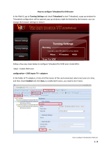
Configuration................................................................................................................... 63
Setting Up an Intermission................................................................................................................... 64
Viewing the Stream............................................................................................................................... 64
Schedule Editing ................................................................................................................................... 65
Record Service ................................................................................................66
Configuration................................................................................................................... 66
Recording a Video Stream .................................................................................................................... 67
Continued

Table o f Co n ten ts
iv
Vision
2
Instruction Manual
Manual Recording........................................................................................................... 67
Scheduled Recording ...................................................................................................... 68
Appendix A: Graceful Startup/Shutdown Procedure ......................................70
Overview ......................................................................................................................... 70
Shutdown ....................................................................................................................... 70
Startup/Restart .............................................................................................................. 71
Troubleshooting ............................................................................................................. 71
No TV signal on screen ......................................................................................................................... 71
No TV signal from Transmitter.............................................................................................................. 71
Appendix B - Backup and Upgrade process ....................................................72
Upgrading the Vision2 Software .................................................................................... 72
Backup Procedure .......................................................................................................... 72
Database Backup Procedure ................................................................................................................ 72
Restore Procedure.......................................................................................................... 72
Appendix C- Troubleshooting .........................................................................73
Time Zone Issue ............................................................................................................. 73

Overview
1
Vision
2
Instruction Manual
Overview
Vision
2
is a sophisticated, fully-integrated video capture, management, and broadcast system for organizations and homeowners
wanting a comprehensive, yet simple-to-use, IP video delivery solution. Vision
2
offers live, scheduled, or on-demand video, all
managed from a convenient web interface. Through the web interface, you can perform the following:
Capture and encode content
Upload, archive, manage, and publish content
Schedule programming
Broadcast at selectable bitrate to any platform
Provide live TV and video on-demand over Intranet to PCs and Set-top boxes attached to displays
Provide video on-demand to supported tablets
Live Channels
Vision
2
services output one or more multicast video streams, called Live Channels, which can be viewed by PC or Set-top box users.
Live Channels are managed by Vision
2
and so they are referred to as managed channels. If using a third party multicast video
stream source, it can be added to Vision
2
as an unmanaged channel. Unmanaged refers to the fact that Vision
2
does not control the
channel. Unmanaged channels also appear in the list of Live Channels available to PC and Set top box users.
Vision2 Services
Vision
2
consists of a number services which correspond to the main video functions. See the table below for a description of each
service.
Components of a Vision2 system
A Vision
2
system can consist of one or more Vision
2
servers. One of the Vision2 servers must be set as the master server, the other
servers known as slaves are subordinate to this server. Typically a V2-MASTER-xxxx server is used as the Master server but it is
possible to use other servers as the master server in smaller installations. User access the Vision2 user interface through a web
page on the master server,
http://<master server name>/v2.aspx. Tablet users connect to http://<master server name>/tablet.aspx
Similarly set-top boxes connect to the master server using the url http://<master server name>/v2.aspx.
The following table lists the different Vision
2
servers:
Vision2 Services
Service Description
Archive Video archive used for viewing videos on demand
DVB Add Digital Tuner channels to your Vision
2
system
Record Record any of the channels in your system to a selected Archive
Producer Create a scheduled TV channel using video stored in your archives
Reflector Transmit your Vision
2
channels over the internet or onto another
subnet
MAX CSE Encoder Use a MAX CSE encoder to add an analogue video source to your
Vision
2
system
Vision2 Server
Name
Description FG number
Master Server (note can also be
used as a Slave Server in a system
which already has a Master Server)
V2-MASTER-0300 FG3106-03
V2-MASTER-1200 FG3106-12
V2-MASTER-2400 FG3106-24
V2-MASTER-3600 FG3106-36
Hosts VOD Archive, Reflector, Producer, and
Record Services. You can only have one Master
Server per Vision2 installation, however the
same hardware can be used as a Slave Server.
Access point for Vision2 user interface. The V2-
MASTER is available with different amounts of
archive storage (Note the storage amounts
quoted in TB are the amounts available for use
by all Archives on the system, not the hard
drive space)
FG3106-03K 1.8 TB
FG3106-12K 9.1 TB
FG3106-24K 18.2TB
FG3106-36K 27.3TB

Overview
2
Vision
2
Instruction Manual
Format Compatibility
The following tables list the formats that are compatible with Live channels and Video on Demand.
* - Some Windows 7 Media Players support MP4.
Server Specifications
The following table lists the specifications for the V2-SERVER-0300 (FG3106-03), V2-SERVER-1200 (FG3106-12), V2-SERVER-
2400 (FG3106-24), and V2-SERVER-3600 (FG3106-36) servers:
Live Channel Compatibility
Amino VLC PC Client WMP Tablet
WMV NoNoYesYesNo
MPEG-2/MPEG-2 TS Yes Yes Yes Yes No
H.264 (AVC)/MPEG-2 TS Yes Yes No No No
H.264 (AVC)/MP4 Yes Yes No No No
Video on Demand Compatibility
Amino VLC PC Client WMP Tablet
WMV No Yes Yes Yes No
MPEG-2/MPEG-2 TS Yes Yes Yes Yes No
H.264 (AVC)/MPEG-2 TS Yes Yes Yes Yes No
H.264 (AVC)/MP4 No Yes Yes No* Yes
FLV (On2 VP6/FLV) No Yes Yes Yes No
MP3 Yes Yes Yes Yes Yes
V2-SERVER Specifications
Processor: 2 x Intel
®
Xeon
®
E5-2620, 2.00 GHz processors
Memory: 16GB RAM
Storage (available): • 1.8 TB (7.2K RPM) (V2-SERVER-0300, FG3106-03)
• 9.1 TB (7.2K RPM) (V2-SERVER-1200, FG3106-12)
• 18.2 TB (7.2K RPM) (V2-SERVER-2400, FG3106-24)
• 27.3 TB (7.2K RPM) (V2-SERVER-3600, FG3106-36)
Power: 1100W (100-240 VAC), 50/60 Hz
NOTE: You can add one additional power supply (V2-POWER-1100) to your
server to provide power supply redundancy.
Front Panel Components:
USB ports 2 USB 2.0 ports for mouse, keyboard, or external peripheral devices
Video connector 1 15-pin (female) video connector for connecting a video output device such as a
PC monitor
Power button Press to power on server.
Rear Panel Components:
Video connector 2 15-pin (female) video connectors for connecting a video output device such as a
PC monitor
Serial connector 1 9-pin (male) serial connector
USB port 3 USB 2.0 ports for mouse, keyboard, or external peripheral devices
LAN connectors 4 RJ-45 LAN ports for connecting to a network router (10/100/1000 Ethernet)
Rack Mount Sliding Ready™ rails with Cable Management arm
Operating Environment: • Operating Temperature: 10º C to 35º C (50º F to 95º F)
• Storage Temperature: -40º C to 65º C (-40º F to 149º F)
• Operating Relative Humidity (non-condensing twmax=29º C): 10% to 80% non-
condensing
• Maximum Humidity Gradient: 10% per hour, operational and non-operational
• Storage Relative Humidity: 5% to 95% non-condensing (twmax=38º C)
• Heat Dissipation: 4100 BTU/hr max
Dimensions (HWD): 3 7/16" (8.73cm) H x 19" (48.24cm) W x 29 3/4" (75.5cm) D
Weight: 71.5 lbs (32.5 kg)
Certifications: CE, NRTL, FCC Class A

Overview
3
Vision
2
Instruction Manual
Vision
2
Expansion Storage
The Vision
2
Expansion Storage V2-STORAGE-2400 (FG3102-01) is an optional accessory that connects directly to your Master
server to allow you to grow the storage capacity of your system. The Expansion Storage is shipped in a RAID configuration in order
to provide resiliency in the event of a disk failure.
The following table lists the specifications for the V2-STORAGE-2400 Expansion Storage (FG3102-01):
Please note that the V2-STORAGE-2400 is only compatible with a V2-MASTER Vision² Master Server (FG3106-XXK) which has a
V2-STORAGE-EXT810 Vision
2
External RAID Controller (FG3102-03) installed.
STB-04 Set-Top Box
The following table lists the specifications for the STB-04 Set-Top Box (FG3100-65):
V2-STORAGE-2400 Expansion Storage Specifications
Storage: 12 2TB 7.2K RPM NL SAS 6Gbps 3.5in HotPlug Hard Drives
Power: • 488W maximum continuous; 550W peak
• 90-264V
• 47-63 Hz
• 7.2A at 100V, 3.6A at 200V
Rear Panel Components:
Output ports 2 SAS connectors for connection to a Master server
Expansion ports 2 SAS connectors for expansion to an additional V2 Expansion storage unit
Operating Environment: • Operating Temperature: 10º to 35º C (50º to 95º F)
• Storage Temperature: -40º to 65º C (-40º to 149º F)
• Operating Relative Humidity: 8% to 85% (non-condensing)
• Storage Relative Humidity: 5% to 95% (non-condensing)
• 1181 BTU per hour
Dimensions (HWD): 3 7/16" (8.7 cm) H x 19" (48.2 cm) W x 23 3/8" (59.4 cm) D
Weight: 62.6 lbs (28.39 kg)
STB-04 Set-Top Box Specifications
Memory: 128MB Flash, 256MB RAM
Power: • 5V DC at 1.5A via external power supply
• Less than 8W typical usage (external supply input voltage 100-240V AC
50-60Hz 3A max)
Front Panel LED: Power on/IR command received (Red)
Rear Panel Components:
Power connector 1 connector port for a 5V DC at 3A power supply
LAN ports 1 x Ethernet 10/100 BaseT via RJ-45 shielded connector
USB port 1 Type-A USB 2.0 port for peripheral connections
HDMI port 1 HDMI 1.3a with HDCP and CEC port
SPDIF port 1 S/PDIF(optical) port
AUDIO VISUAL port 1 10-way Mini-DIN for Composite video, Component (YPrPb), RGB, S-Video, and
analog audio
IOIOIO port 1 IR extender and TVI port
Codecs: • MPEG-2 MP@HL
• MPEG-4 pt10 AVC/H.264 HP@L4
Video Resolution: Up to 720p and 1080i. The video output resolution on the STB should be set to
720p.
Graphics Resolution: HD graphics up to 1280x720
Audio: • Analog stereo audio out
• Stereo and Dolby 5.1 surround via S/PDIF and HDMI
• Dolby Digital+ pass through to external decoder
Operating Environment: • Operating Temperature: 0º to 40º C (32º to 104º F)
• Storage Relative Humidity: 5% to 95% (non-condensing)
Dimensions (HWD): 1 9/16" (4cm) H x 5 1/2" (14cm) W x 4 1/2" (11.4cm) D
Weight: 0.70 lbs (0.32 kg)
Included Accessories: • 1 Amino Universal Remote Control

Overview
4
Vision
2
Instruction Manual
Vision2 Network Switch Requirements
Vision
2
requires a Gigabit layer 2/3 network switch with IGMP Snooping/Querier support. The network switch should meet the
following requirements:
Using Vision2 without a DNS Server
Using Vision
2
with a DNS Server is recommended. If a DNS Server is not available, the hosts file will need to be edited on each
Vision
2
server and the names and IP addresses of all your Vision
2
servers added. The hosts file is located in the folder
C:\windows\system32\drivers\etc. FIG. 1 shows a hosts file for a setup with one master server called V2MASTER with IP address
192.168.20.110 and one Digital TV Appliance called V2DVBGATEWAY with IP address 192.168.20.111.
NOTE: If a DNS server is not available and the name of a server needs to be changed, you will have to update the name of the server
in the host file on each of the servers which make up the Vision
2
system.
Network Switch Requirements
Physical Interfaces: RJ-45 connectors for 10Base-T, 100Base-TX, 1000Base-T with 8, 16, 24, or 48
ports.
Layer 2 Services: • IGMP Snooping V1 or V2 (Not router dependant for operation)
• IGMP Querier
• Layer 2/3 switching
• Spanning Tree Protocol (STP)
Security: • QoS
• Storm Control Broadcast and Multicast
Performance Specifications: Jumbo frame support
Switching Capacity: Non Blocking 32Gbps (16Port) - 140Gbps (48Port)
Forward Rate: 24Mpps (16Port) - 96Mpps (48Port)
Internet Protocol: IPv4 or IPv6
Optional: • VLAN support
• Web User Interface
FIG. 1 Example Hosts File

Wiring and Device Connections
5
Vision
2
Instruction Manual
Wiring and Device Connections
V2-Master Server Rear Panel Connections
This section details the ports and connectors on the rear panel of the Vision
2
Master server.
The two flex drives at the rear of the V2-Master server are f itted with 146GB 15K SAS 2.5in Hot-Plug Drives conf igured as Raid1 for
the OS (Microsoft Windows Server 2008 Standard)
LAN (RJ-45) Port
FIG. 4 describes the blink activity for the LAN 10/100/1000 Base-T RJ-45 connector and cable.
NOTE: Vision
2
uses typical Cat5/5e/6 cabling for RJ-45 connections.
The following table lists the pinouts, signals, and pairing associated with the LAN connector.
FIG. 2
Vision
2
Master Server Rear Panel
FIG. 3 LAN (RJ-45) Port
FIG. 4 LAN Connector / LEDs
LAN RJ-45 Pinouts and Signals
Pin Signals Connections Pairing Color
1 TX + 1 --------- 1 1 --------- 2 Orange-White
2 TX - 2 --------- 2 Orange
3 RX + 3 --------- 3 3 --------- 6 Green-White
4 no connection 4 --------- 4 Blue
5 no connection 5 --------- 5 4 --------- 5 Blue-White
6 RX - 6 --------- 6 Green
7 no connection 7 --------- 7 7 --------- 8 Brown-White
8 no connection 8 --------- 8 Brown
Output port
LAN ports
Power connector
ETHERNET
A L
A - Activity LED (yellow)
lights when receiving or
transmitting LAN
data packets
L - Link LED (green) lights when
the LAN cables are connected
and terminated correctly.

Wiring and Device Connections
6
Vision
2
Instruction Manual
FIG. 5 diagrams the RJ-45 pin-outs and signals for the LAN RJ-45 connector and cable.
Set-Top Box Connections
The STB-04 Set-Top Box (FG3100-65) supports viewing the Live Channels from MAX CSE Encoders, Producers, Reflectors, or DVB
Tuners. The set-top boxes access the Vision
2
server and display available programming on a connected video source. The set-top
boxes are used only for MPEG 2 content. They support viewing MPEG Video on Demand Stop, Play, and Pause, Fast Forward and
Rewind features.
NOTE: The Set-Top Boxes support video up to a resolution of 720p or 1080i. Sending video with greater resolution could cause the
set-top boxes to reset themselves periodically.
FIG. 6 displays the rear panel of the STB-04 Set-Top box.
FIG. 5
RJ-45 Wiring Diagram
FIG. 6 STB-04 Set-Top Box (rear-view)
USB port
SPDIF
port
LAN
port
Power
HDMI port
Audio/Video port
IR Extender/TVI port

Installation
7
Vision
2
Instruction Manual
Installation
This section provides instructions on how to install the different Vision
2
accessories.
Installing Master Server Accessories
Optional accessories can be installed in the Master server for redundant power or for connection to an Archive server.
Installing a Secondary Power Supply
The V2-POWER-1100 (FG3106-PS) is a secondary power supply that can be used to add redundant power to FG3106-XX Vision
2
Master Servers. Master servers ship with a single 1100W power supply. One additional V2-POWER-1100 can be added to the server
to provide power supply redundancy.
NOTE: The V2-POWER-1100 power supply is only compatible with the FG3106-XX Vision
2
Master servers
Follow these steps to install a secondary power supply.
1. Remove the metal cover from the power supply expansion slot (see FIG. 8).
2. Slide the secondary power supply into the slot until the orange tab beside the power connector clicks into place.
Installing Expansion Storage
The following steps describe how to add an additional 24TB of Disk storage to an existing archive server.
1. Connect an SAS cable to the IN port on the rear of the V2-STORAGE-2400 Expansion Storage device (FIG. 10).
2. Connect the other end of the cable to the first SAS port on the rear of the Master server.
FIG. 7
V2-POWER-1100 Power Supply
FIG. 8 Master Server Rear Panel
FIG. 9 Vision
2
Archive/Video on Demand server with V2-PVA (rear-view)
FIG. 10 V2-STORAGE-2400 Expansion Storage (rear-view)
Remove metal cover
from expansion slot.

Installation
8
Vision
2
Instruction Manual
Set-Top Boxes
The STB-04 (FG3100-65) Set-Top Box supports viewing live programming via a Producer channel, MPEG encoder, or DVB Tuner
channel. The set-top boxes access the Vision
2
server and display available programming on a connected video source. The set-top
boxes are used only for MPEG2 and MP3 content. They support viewing MPEG Video on Demand, but support only Stop, Play,
Pause, Fast Forward, and Rewind features.
NOTE: The Set-Top Boxes have a limit of 18Mbps. Heavy traffic loads can cause the set-top box to reset itself periodically.
FIG. 11 displays the rear panel of the STB-04 Set-Top box.
NOTE: Do not use the reset button on the back of your set-top box.
Conf iguring the Set-Top Box
Before a set-top box can be used to view a video source, it must be configured to access the Vision
2
server. Plug a USB keyboard
into the USB port on the front of the set-top box.
NOTE:
The set-top-box will need to be power cycled to allow it to recognize the keyboard.
Perform these steps to configure the set-top box:
1. Connect the power supply to the power connector on the rear of the unit.
2. Choose one of the following methods to connect the set-top box to audio and video sources:
Use an HDMI cable to connect the HDMI port on the set-top box to an HDMI port on the video source. HDMI also transmits
an audio signal in addition to video.
Use a breakout cable to connect the AUDIO VISUAL port on the set-top box to your audio and video sources. In place of
connecting the breakout cable to your audio source, you can connect an optical audio cable from the SPDIF port on the
set-top box to your audio source.
3. Connect an RJ-45 LAN cable to LAN port 1 on the rear of the unit. The other end of the cable connects to your LAN. This
connection accesses your Vision
2
server and can be used to upload the latest firmware and Vision
2
menus to the set-top box.
Management Pages
Login to the management pages on your set-top box as follows:
1. Press Alt-M on the keyboard to access the Enter Management Pages login, see FIG. 12
2. In the Password text box, enter the password (the default is leaves) and press Enter. The Set-top box Management screen
appears
3. Check that your set-top box has the correct firmware and opera browser installed, using the arrow keys on the keyboard to
access User Prefs and press the right arrow cursor key to enter this page
4. You are prompted whether you want to enter the User Preferences page. Press enter and use the right/left cursor keys to
change this setting to Yes.
FIG. 11
STB-04 Set-Top Box (rear-view)
FIG. 12 Enter Management Password (default password - leaves)

Installation
9
Vision
2
Instruction Manual
5. Press enter again to confirm the new setting. The unit will prompt for the write password for modifying settings in the space
provided (the default is snake). You will need to enter this password whenever you change settings.
6. A new set of menus should now be visible. Select the info menu and check the software version. Ensure that Opera 10 version
2.34 or 2.5.2 is running (FIG. 13).
7. Select the back option and return to the main menu.
Set-Top Box Networking
Setup networking on the set-top box as follows:
1. Select the DHCP menu.
2. Change the DHCP setting to disabled.
3. Enter an IP address, Netmask, Gateway and (optional) DNS server setting for the set top box.
Browser Homepage
Set the browser home page for your set-top box to point to a page on your Vision2 master server:
1. Use the arrow keys on the keyboard to access the Browser option, and press the right arrow cursor key to enter this page
(FIG. 15).
FIG. 13
Software Version
FIG. 14 Network Settings
FIG. 15 Set-Top Box Browser Configuration

Installation
10
Vision
2
Instruction Manual
2. Select the home page setting using the cursor keys and press the DEL key to start editing.
3. Delete any text using the backspace key and then enter the address of the Vision
2
master server. If using a DNS server, either
enter the hostname of server, otherwise enter the server’s IP address. The URL is as follows:
http://<master server name>/aminoH140.aspx
or if there is no DNS server
http://<master server IP>/aminoH140.aspx
NOTE: The set-top box must be configured to point at the master server, not to any of the slave servers
4. Press enter and another Password prompt appears. Enter the password for modifying settings in the space provided (the
default is snake).
5. Set Full screen mode setting to Disabled, and GFX resolution to 720 HD..
Video Settings
Configure the video settings as follows:
1. Return to the User Prefs menu and select the Video page (FIG. 16).
2. Change the TV type setting to the correct aspect ratio for the attached display (e.g. 16:9).
3. Change the output resolution to 720p.
4. Select the back option and choose yes to return to the main menu.
Restart the set top box by selecting Restart followed by Yes and press Enter to reboot the set-top box.
NOTE: The Amino Set-Top Box must have both its GFX resolution and Output resolution set to 720p in order to ensure proper
operation.
FIG. 16
Video Settings

Installation
11
Vision
2
Instruction Manual
Using the Remote Control
The set-top box includes a universal remote control to control the video display and navigate through the Vision
2
menus. Not all
buttons on the remote work with your Vision
2
setup. While Vision
2
supports Video on Demand, you can use only the Play, Pause,
Stop, Fast-Forward, and Rewind features. FIG. 17 highlights some of the buttons you can use with Vision
2
and your set-top box.
NOTE: Subtitles are only supported on DTV streams.
NOTE: If using an STB-04 set-top box and you receive a "failed to load webpage" error, select the OK button on the remote and, using
the remote, power the set-top box off and on again. Afterward, the Vision
2
main menu loads.
After the set-top box reboots, it accesses the specified Vision
2
master server and downloads the latest Vision
2
menus.
NOTE: Ensure the set top box has Opera version 10 installed. Opera 11 is not supported.
The Vision
2
menus can be accessed by pressing the Menu button on the remote control. The Vision
2
Main Menu (FIG. 18) contains
two options discussed in detail in the following sections: Live TV Feeds and Video on Demand..
FIG. 17
Amino Remote Control
FIG. 18 Vision
2
Main Menu
Volume control
Play
Pause
Stop
Power
Navigational buttons for manuvering
through the Vision
2
menus
Menu button for accessing
the Vision
2
menu
Turn on Subtitles

Installation
12
Vision
2
Instruction Manual
Live TV Feeds
The Live TV Feeds menu (FIG. 19) displays a listing of all Live Channels available in the Vision2 system. Use the remote control to
scroll through the channels and press OK on the remote control to select and view a channel. See the Using the Remote
Control section on page 11 for more information on using the remote.
Video on Demand
The Video on Demand menu displays a listing of all available video archives (FIG. 20).
Use the remote control to scroll through the list of archives and press OK to enter an archive. Within an archive will be a number of
categories. Use the cursor keys on the remote to navigate to and highlight the desired category. Click OK to navigate into the
category.
Use the same method to select a video/audio file within a folder. Select a Video (FIG. 21) and click OK to view the video thumbnail
fullscreen along with any metadata associated with the video (FIG. 22). Click OK again to play the video. See the Using the Remote
Control section on page 11 for more information.
FIG. 19
Live TV Channels
FIG. 20 Video On Demand Section - List of Archives
FIG. 21 Selecting a Video to Play

Installation
13
Vision
2
Instruction Manual
FIG. 22 Video Metadata

Installation
14
Vision
2
Instruction Manual
FIG. 23 displays an example of video on demand programming. While viewing video on demand programming, you can use the
remote control to pause or stop the video stream. If you press OK on the remote control while a video is playing then a seek bar
appears. Press Left or Right on the control while the seek bar is displayed to move to the correct location in the video and then press
OK again to resume playback.
Use the Play button to resume viewing a paused video stream. To refresh your set top box to display new content in your archive or
to refresh the template displayed, navigate away from the main menu into the Live Channels or Video on Demand pages and press
and hold the menu button for a second or more. The screen should flash and will return to the main menu. The set-top box will
refresh and the new template and new Archive content can be viewed.
The set-top box also has a search feature, select the search icon and click OK to open the search dialogue box, see FIG. 24. Enter
the text you want to search for and click GO, this returns any matching videos. Note that the search is case-insensitive.
FIG. 23
Video Playback and Seek Bar
FIG. 24 Search Feature
/