Page is loading ...

Installation Instructions
Installation Instructions
SERIN
™
Wall Mount Electronic
Proximity Lavatory Faucet
Certified to comply with ASME A112.18.1
© 2016 American Standard
Product No.'s & Options
Specications
Faucet Installation
Electrical Installation
Start-up / Maintenance
FAQ’s / Troubleshooting
Replacement Parts
1
2
2-5
6-8
9-10
10-11
12
T064.34X T064.35X T06B.30X
MODEL NUMBERS
M965613 REV. 1.8 (11/16)
NOTE: Please refer to R350 Mounting Kit
installation instructions #M965614 prior to
faucet installation.
NOTE TO INSTALLER: Please give this manual to the customer after installation.NOTE TO INSTALLER: Please give this manual to the customer after installation.
To learn more about American Standard Selectronic
®
Products visit our website at: www.americanstandard-us.com
or e-mail us at: CRTTEAM@americanstandard.com
For Parts, Service, Warranty or other Assistance,
please call (844) CRT-TEAM / (844) 278-8326 (In Canada: 1-800-387-0369)
(In Toronto Area only: 1-905-306-1093)
CAUTION: Use only American Standard supplied
transformers and cable sets. Using non-AS
supplied cables, or cutting, splicing or modifying
any components will void the warranty.

M965613 REV. 1.8 (11/16)
1
6. Control box
7. Mixing Valve (optional, must be ordered separately)
8. Control Box Cover Screws
All American Standard Faucets Are Water Tested At Our Factory.
Some Residual Water May Remain In The Faucet During Shipping.
Thank you for selecting American-Standard...the benchmark of fine quality for over 100 years. To ensure
that your installation proceeds smoothly--please read these instructions carefully before you begin.
UNPACKING
1. Remove the fitting and loose items from the carton. The illustration below shows the fitting and all loose items
after they have been removed from the carton. Some items may be packaged partially assembled to other items.
605XTMV1070 R350 MOUNTING KIT
(Must have R350 Mounting Kit
installed prior to Wall Mount
faucet installation)
PRODUCT No.s
2
4
1
7
5
6
Mixing ValveBase Product
Spout
All T064. SERIES
3
1. Installation Instructions
2. Spout Assembly
3. Elbow Kit
4. Mounting Kit
5. Supply Hose
Installation Instructions
In s tal l at i on I ns t ruct i on s
SERIN™
Wall Mount Electronic
Proximity Lavatory Faucet
Certified to comply with ASME A112.18.1
© 2014 American Standard
M965613 REV. 1.3 (11/14)
Product No.'s & Options
Specications
Faucet Installation
Electrical Installation
Start-up / Maintenance
FAQ’s / Troubleshooting
Replacement Parts
1
2
2-5
6-8
9-10
10-11
12
T064.342
T064.353
T064.362
T064.372
T064.392
T064.345
T064.355
T064.365
T064.375
T064.395
MODEL NUMBERS
CAUTION: Use only American Standard
supplied cable sets. Using non-AS supplied
cables, or cutting, splicing or modifying any
components will void the warranty.
NOTE: Please refer to R350 Mounting Kit
installation instructions #M965614 prior to
faucet installation.
NOTE TO INSTALLER: Please give this manual to the customer after installation.NOTE TO INSTALLER: Please give this manual to the customer after installation.
To learn more about American Standard Selectronic
®
Products visit our website at: www.americanstandard-us.com
or e-mail us at: [email protected]
For Parts, Service, Warranty or other Assistance,
please call (844) CRT-TEAM / (844) 278-8326 (In Canada: 1-80 0-387-0369)
(In Toronto Area only: 1-905-306-1093)
8
Plug-In AC
Power Kit
Hard-Wired AC
Power Kit
Multi-AC
Power Kit
PK00.PAC
PK00.HAC PK00.MAC
POWER KITS SOLD SEPARATELY

RECOMMENDED TOOLS
1 Slip Jaw Pliers
2 Adjustable Wrench
3 Plumbers' Putty or Caulking
4 Phillips Screwdriver
5 Flat Blade Screwdriver
6 Electric Drill & 1/4"
Drill Bit
7 Tape Measure
1
2
1
2
3
4
5
6
7
10'
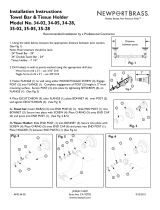
SPOUT ASSEMBLY INSTALLATION;
Fig. 1
FAUCET INSTALLATION
CAUTION
Turn off hot and cold water
supplies before beginning
1
1. Remove both MOUNTING SCREWS (1), then
remove upper PLASTIC GUARD (2). Remove the
CORD HOLDER (3a) and CABLE HOLDER (4a)
from the PLASTER GUARD (2).
IMPORTANT: Secure the CORD HOLDER (3a)
and the CABLE HOLDER (4a) from falling back
through the hole in the wall.
2. Remove the two EXTENSION CABLE ENDS (5a)
from the CABLE HOLDER (4a).
IMPORTANT: Secure the CORD HOLDER (3a)
and the EXTENSION CABLES (5a) from falling
back through the hole in the wall.
3. Remove the CORD HOLDER (3b) and CABLE
HOLDER (4b) from the two bottom PLASTER
GUARDS (6).Use a flat blade screwdriver to break
off the two ends of the lower PLASTER GUARDS
(6) flush with the finished wall.
IMPORTANT: Be carefull not to damage the wire
cables. Secure the CORD HOLDER (3b) and the
CABLE HOLDER (4b) from falling back through
the holes in the wall. Remove the two EXTENSION
CABLE ENDS (5b) from the CABLE HOLDER (4b).
M965613 REV. 1.8 (11/16)
Fig. 1
2
3/8" COMP.
*ELECTRICAL
BOX
(supplied by others)
Roughing-in Dimensions
GENERAL DESCRIPTION:
Electronic faucet with proximity operation. Vandal
resistant solid brass construction single post
mounting. Operates on DC (battery/power pack) or
AC permanent power (plug-in/hardwire). In-line
strainer for solenoid is integral. Single inlet 3/8
compression, built-in checks, and flexible stainless
steel 16-1/4" reach inlet hose for spout connection.
Note: All plumbing and electrical wiring must be
installed in accordance with applicable codes,
regulations and standards.
*RECOMENDED CONTROL BOX OR
EQUIVALENT BY OTHERS
CONTROL BOX IS ONLY REQUIRED FOR
HARD-WIRED AC INSTALLATIONS (.392 & .395)
4" (102mm) SQ. X 3-1/2" (89mm) DEEP CONTROL BOX
Hubbel-RACO #256 OR EQUAL (BY CONTRACTOR).
102 - 203mm Recommended
(4" - 8" Recommended)
70mm (2-3/4) DIA.
FINISHED FLOOR
81mm
(3-3/16)
150mm - 225mm
MIN. (5-7/8) - MAX. 8-7/8
FINISHED WALL
29-1/2" MAX.
(750mm)
6
5b
5b
4b
3a
3b
6
5a
5a
4a
CAUTION: Use only American Standard supplied
transformers and cable sets. Using non-AS
supplied cables, or cutting, splicing or modifying
any components will void the warranty.

INSTALL SPOUT MOUNTING KIT;
Fig. 2
1a
M965613 REV. 1.8 (11/16)
Fig. 2
Fig. 3
Fig. 4
1. Make sure that SEAL (7) is installed into the groove
on the back of the MOUNTING FLANGE (8). Feed
the CORD HOLDER (3a) and the EXTENSION
CABLES (5a) through the MOUNTING FLANGE (8).
2. Install the MOUNTING FLANGE (8) to the wall with
three SCREWS (9) that thread into the MOUNTING
PLATE (10) within the wall. DO NOT fully tighten
the SCREWS (9). HAND TIGHTEN ONLY.
1. Slide SPOUT ESCUTCHEON (11) onto SPOUT (12).
2. Slide COMPRESSION RING (13) and
COMPRESSION SEAL (14) onto SPOUT (12).
3. Connect SPOUT HOSE (15) onto CORD HOLDER (3a)
by pressing until secure connection is achieved .
INSTALL SPOUT ASSEMBLY;
Fig. 3
1b
1. Connect the FAUCET SENSOR CONNECTORS (16)
to the EXTENSION CABLES (5a), and secure the
connections by installing into CONNECTOR HOUSINGS
(17) as shown. Rotate the END CAPS (18) to secure the
connection within the CONNECTOR HOUSINGS (17).
2. Pull the bottom end of EXTENSION CABLES (5b)
so that the CONNECTOR HOUSINGS (17) are inside
the wall.
4. Pull bottom CORD HOLDER (3b) and fish SPOUT
HOSE (15) through the wall and out through the
bottom wall opening (19).
5. Cut the CORD HOLDER (3a) off the end of the
SPOUT HOSE (15) as shown.
IMPORTANT: Secure the SPOUT HOSE (15) from
falling back through the wall opening (19).
SECURE WIRE CONNECTIONS;
Fig. 4
1c
3
7
10
8
3a
9
5a
3b
3a
15
17
16
19
17
18
18
5a
5b
11
15
3a
13
14
12
CUT SPOUT
HOSE

M965613 REV. 1.8 (11/16)
Fig. 5
ALIGN SPOUT ASSEMBLY;
Fig. 5
4
12
8
12
11
13
20
21
1d
1. Align and push SPOUT (12) through hole, loosely
installed MOUNTING FLANGE (8) and MOUNTING
PLATE (10).
2. Once MOUNTING FLANGE (8) is aligned with
MOUNTING PLATE (10) opening, tighten the three
MOUNTING FLANGE SCREWS (9). (Tighten each
screw little by little to avoid missalignment!)
3. Align and slide and COMPRESSION SEAL (14) and
COMPRESSION RING (13) to MOUNTING FLANGE (8).
1. Once MOUNTING FLANGE (8) is installed, move the
SPOUT (12) in or out to determine desired spout length
from finished wall. Note: The Min. is 150mm, (5-7/8)
and the Max. is 225mm, (8-7/8) from the finished wall
to center of the spout end.
2. Tighten COMPRESSION RING (13) to MOUNTING
FLANGE (8) by tightening the three COMPRESSION
RING SCREWS (20) with HEX WRENCH (21) supplied.
This will fix SPOUT (12) length from finished wall.
3. Push ESCUTCHEON (11) to MOUNTING FLANGE (8)
and hand tighten to complete spout installation.
150mm - 225mm
MIN. (5-7/8) - MAX. 8-7/8
Fig. 6
SPOUT LENGTH
150mm - 225mm
MIN. (5-7/8) - MAX. 8-7/8
12
13
14
8
13
14
10
10
9
9
SECURE SPOUT ASSEMBLY;
Fig. 6
1e
8

M965613 REV. 1.8 (11/16)
5
INSTALL SUPPLY ELBOW
ASSEMBLY & CONTROL BOX;
Fig. 7 and Fig. 7a
1. Install HOSE CLAMP (22) onto SPOUT HOSE (15).
Install SPOUT HOSE (15) onto ELBOW NIPPLE (23).
Fully tighten HOSE CLAMP (22) to secure SPOUT
HOSE (15) to ELBOW ASSEMBLY (24). Fig. 7.
2. Using the ANCHORS (25) and SCREWS (26) supplied,
attach ELBOW ASSEMBLY (24) to finished wall, covering
the hole in wall. Fig. 7.
3. Remove CONTROL BOX COVER (27). Feed
EXTENSION CABLES (5b) THROUGH GROMMET (28)
in back of CONTROL BOX (29). (Refer to VIEW “A”). Hold
the CONTROL BOX (29) so that it covers the wall opening
and mark the four mounting hole locations as shown. Fig.
7a.
4. It is recommended that the CONTROL BOX (29) be
secured to a wall stud or cross brace within the wall using
the SCREWS (30) supplied. If the CONTROL BOX (29) is
to be installed on tile or plaster walls, the ANCHORS (31)
and SCREWS (30) should be used.
2
22
25
26
27
29
31
30
28
24
15
23
Fig. 7
Fig. 7a
5b
VIEW “A”
VIEW “A”
32
35
33
34
24
29
Fig. 8
LAVATORY RIM OR
MOUNTING SURFACE
NOTE: If using Mixing Valve (optional) See Sheet
#M968808 for installation instructions.
CONNECT SPOUT HOSE TO
CONTROL BOX; Fig. 8
3
1. Connect G 1/2˝ end of SUPPLY HOSE (32) to the
ELBOW ASSEMBLY (24). Tighten with adjustable
wrench to make a water tight connection.
2. Connect G 3/8˝ end of SUPPLY HOSE (32) to nipple
on top of CONTROL BOX (29). Tighten with adjustable
wrench to make a water tight connection.
3. IMPORTANT: INSERT FIBER WASHER (33)
INTO SUPPLY NUT (34) ON CONTROL BOX (29).
4. Connect FLEXIBLE SUPPLY (35) to bottom SUPPLY
NUT (34). Connect other end directly to wall supply.
Connection is G 3/8" compression.
Note: FLEXIBLE SUPPLY (35) measures 20" from the
bottom of the CONTROL BOX (29) base. If additional
supply length is required, installer must purchase parts
separately. If FLEXIBLE SUPPLY (35) is too long, loop to
avoid kinking.
COLD WATER OR
TEMPERED
WALL SUPPLY
CONTROL BOX
FOR HARDWIRE
INSTALLATION
(supplied by others)
9" TO 12"
(229mm TO 305mm)
NOTE: Find plastic bag containing 4 M5X16 screws
to be used for securing the CONTROL BOX COVER (1)
when installation is complete.

M965613 REV. 1.8 (11/16)
6
1. Remove CONTROL BOX COVER (1) from
CONTROL BOX (2). Fig. 1.
2. Feed the EXTENSION CABLE (3) from the Faucet
through SIDE GROMMET (4). Fig. 1a.
3. Connect SOLENOID CABLE (5) to EXTENSION
CABLE (3) from the Faucet. Fig. 1a.
4. Insert BATTERY (6) into BATTERY HOLDER (7),
make sure the shape of the BATTERY (6) follows the
shape of the BATTERY HOLDER (7) and terminal
end is inserted first. Fig. 1b.
5. Connect the BATTERY CONNECTOR (7a) from the
Standard or PWRX Battery to EXTENSION CABLE
(8) as shown. Fig. 1c. Place Standard Battery or
PWRX into Housing. Fig. 1d.
6. Replace CONTROL BOX COVER (1). Tighten cover
screws firmly.
PWRX & STANDARD
BATTERY; Fig. 1
A
ELECTRICAL INSTALLATION
Fig. 1a
Fig. 1b
Fig. 1
Fig. 1c
5
5
Fig. 1d
3
2
1
6
7
INSTALL BATTERY
STANDARD
BATTERY
STANDARD
BATTERY
PWRX
CR-P2
7a
7a
8
4
PWRX
CAUTION: Use only American Standard supplied
transformers and cable sets. Using non-AS
supplied cables, or cutting, splicing or modifying
any components will void the warranty.
Product Page
Plug-in AC Powe Kit
(PK00.PAC)
7
Hard-Wired AC Prower Kit
(PK00.HAC)
7
MULTI-AC Power Kit
(PK00.MAC)
8

M965613 REV. 1.8 (11/16)
7
Fig. 2
Fig. 2a
Fig. 3
Fig. 3a
BLACK & WHITE
POWER
CONNECTIONS
16
12
CONNECTOR NOT
USED IN THIS
INSTALLATION
12
10
11b
15
4" CONTROL BOX
OR EQUIVALENT BY
OTHERS
14
AC POWER
SUPPLY
2
1
4
10
AC POWER
SUPPLY
9
8
AC VERSIONS (HARDWIRE / PLUG-IN);
Fig. 2 and Fig. 3
B
CAUTION
Before opening CONTROL BOX
disconnect AC power supply.
1. Remove CONTROL BOX COVER (1) from CONTROL BOX
(2). Fig. 2.
2. Feed the EXTENSION CABLE (3) from the faucet through
GROMMET (4). Then connect the SOLENOID CABLE (5) to
EXTENSION CABLE (3). Install CONNECTOR LOCKING
DEVICE (6). Fig. 2a.
3. Insert POWER CORD (9) through OUTER GROMMET (10)
as shown. Connect it to the SINGLE AC ADAPTER (11). Fig. 2a.
4. Connect POWER CORD (9) to EXTENSION CABLE (8)
from faucet sensor. Replace CONTROL BOX COVER (1).
Tighten cover screws firmly.
Prior to making power connection, make sure
detection zone is not obstructed. Sensor is
self adjusting. Keep detection zone clear for 15
seconds after power is connected.
5. Plug AC POWER SUPPLY into wall outlet. Fig. 2a.
FOR HARDWIRE HOOKUP ONLY; Fig. 3
6. Insert 10 ft. EXTENTION (11a) from HARD WIRE POWER
SUPPLY (12) into CONTROL BOX through OUTER GROMMET
(10) and side GROMMET (4). Connect 10' Extension (11a) to
SINGLE AC ADAPTER (13). Fig. 3.
7. Insert EXTENSION CABLE (8) from faucet through
GROMMET (4a) and connect to SINGLE AC ADAPTER (13).
Replace CONTROL BOX COVER (1). Tighten cover screws
firmly. Fig. 3.
Contractor to supply ELECTRICAL BOX (14) and power to
POWER SUPPLY (12). Fig. 3a.
8. Connect White and Black connections to POWER SUPPLY
CONNECTIONS (15). Fig. 3a.
Prior to making power connection, make sure
detection zone is not obstructed. Sensor is
self adjusting. Keep detection zone clear for 15
seconds after power is connected.
9. Connect the 10 ft. EXTENSION (11b) to the POWER SUPPLY
CABLE (16). Mount POWER SUPPLY (12) into ELECTRICAL
BOX (14).
FOR PLUG-IN HOOKUP ONLY; Fig. 2
11a
13
7
3
8
4
4a
!
!
CAUTION: Use only American Standard supplied
transformers and cable sets. Using non-AS
supplied cables, or cutting, splicing or modifying
any components will void the warranty.
5
3
11
6

M965613 REV. 1.8 (11/16)
8
Fig. 4
Fig. 4a
Unit #1 Unit #2 Unit #3
AC POWER
SUPPLY
O
R
*MAXIMUM OF 15 UNITS PER AC POWER SUPPLY.
10' MAXIMUM CABLE LENGTH BETWEEN UNITS.
4" (102mm) SQ. X 3-1/2" (89mm) DEEP CONTROL BOX
Hubbel-RACO #256 OR EQUAL (BY OTHERS).
10 ft. EXTENSION
CABLE
10 ft. EXTENSION
CABLE
FOR AC-VERSION
(MULTI HOOK-UP); Fig. 4 and Fig. 4a
C
Unit #1 Detail
AC POWER
17
3
13
18
11b
5
4
4a
8
11a
1. Remove COVERS from all CONTROL BOX (2).
Fig. 4 and Fig. 4a.
2. Remove SOLID BLACK PLUG GROMMET (17) from
left side of all CONTROL BOX (2). Replace with GRAY
GROMMET (18). (Supplied with each Faucet).
Fig. 4 and Fig. 4a.
3. Feed the EXTENSION CABLE (3) from the Faucet
through GROMMET (4) and connect it to the
SOLENOID CABLE (5). Fig. 4 and Fig. 4a.
4. Feed the EXTENSION CABLE (8) from the Faucet
through GROMMET (4a) and connect to either of the
two terminals at the one end of the Y-ADAPTER (13).
Connect the 10 ft. EXTENSION (11a) to the other
terminal at the same end of the Y-ADAPTER (13).
Fig. 4 and Fig. 4a.
5. Feed the other end of the 10 ft.EXTENSION (11b)
through the two GRAY GROMMETS (4a and 4b) and
connect to the single terminal end of the next unit’s
Y-ADAPTER (13). Place Y-ADAPTER (13) into
CONTROL BOX (2) as shown in Fig. 4 and Fig. 4a.
6. Repeat Steps above for each additional Unit, for a
Max. of 15 Units on one AC POWER SUPPLY.
7. Replace CONTROL BOX COVERS. Tighten cover
screws firmly.
YOU CAN USE EITHER THE PLUG-IN
OR HARD-WIRED TRANSFORMER.
YOU CAN USE EITHER THE PLUG-IN
OR HARD-WIRED TRANSFORMER.
4b
2
OR
CAUTION: Use only American Standard supplied
transformers and cable sets. Using non-AS
supplied cables, or cutting, splicing or modifying
any components will void the warranty.

M965613 REV. 1.8 (11/16)
9
Fig. 2
Fig. 1
DETECTION
ZONE:
BETWEEN
SPOUT AND
BASE OF SINK
Fig.3
K
C
R-P2
3
6
4
5
2
1
STANDARD
BATTERY
7/16" SOCKET
WHITE
DEBRIS
CUP
FILTER
SCREEN
•
•
•
•
•
•
•
•
•
•
•
•
•
•
•
•
•
•
•
•
•
•
•
•
•
•
•
•
•
•
•
•
•
•
•
•
•
•
•
•
•
•
•
•
•
•
•
•
•
•
•
•
•
•
•
•
•
•
•
•
•
•
•
•
•
•
•
•
•
•
•
•
•
•
•
•
•
•
•
•
•
•
•
•
•
•
•
•
•
•
•
•
•
•
•
•
•
•
•
•
•
•
•
•
•
•
•
•
•
•
•
•
•
•
•
•
•
•
•
•
•
•
•
•
•
•
•
•
•
•
•
•
•
•
•
•
•
•
•
•
•
•
•
•
•
•
•
•
•
•
•
•
•
•
•
•
•
•
•
•
•
•
•
•
•
•
•
•
•
•
•
•
•
•
•
•
•
•
•
•
•
•
•
•
•
•
•
•
•
•
•
•
•
•
•
•
•
•
•
•
•
•
•
•
•
•
•
•
•
•
•
•
•
•
•
•
•
•
•
•
•
•
•
•
•
•
•
•
•
•
•
•
•
•
•
•
•
•
•
•
•
•
•
•
•
•
•
•
•
•
•
•
•
•
•
•
•
•
•
•
•
•
•
•
•
•
1. Remove COVER from CONTROL BOX (1).
2. Disconnect BATTERY HOLDER (3) from SENSOR
CABLE (5).
3. Remove old BATTERY from BATTERY HOLDER (3).
Install new BATTERY (2) making sure the terminal side
is inserted first and shape of the battery follows the
shape of the BATTERY HOLDER (3).
4. To change PWRX BATTERY PACK (4), unplug and
replace with new Power Pack.
5. Reconnect BATTERY HOLDER (3) to SENSOR
CABLE (5).
6. Replace CONTROL BOX COVER. Tighten cover screws
firmly.
HOW TO INSTALL AND CHANGE
BATTERY; Fig. 2
B
1. Remove CONTROL BOX COVER.
2. Close SUPPLY STOP (13) with 4mm Hex wrench.
Note: Activate sensor to keep water flowing out of
faucet while shutting off.
3. Unthread FILTER ASSEMBLY (6) using a 7/16" socket.
4. Pull out the FILTER ASSEMBLY (6), remove and clean
white debris cup and filter screen.
5. Install the FILTER ASSEMBLY (6) back in its place and
tighten with a 7/16" socket.
Caution: Do not over tighten.
6. Open SUPPLY STOP (13) with 4mm Hex wrench.
7. Replace CONTROL BOX COVER. Tighten cover
screws firmly.
HOW TO CLEAN FILTER
ASSEMBLY; Fig. 3
C
CAUTION
Before opening CONTROL BOX
disconnect AC power supply.
START-UP / MAINTENANCE
When the Sensor detects a user, the water immediately
starts to flow. Water flow will stop 1.5 seconds after user
is out of sensor range. This comfort timer allows the user
to move his hands without the flow cycling on and off. As
a precaution, a safety timer will turn off the water after
the sensor has been blocked for 55 seconds. Water flow
will resume when the blockage is removed from the
detection zone and the sensor is activated again.
HAND WASH SENSOR OPERATION;
Fig. 1
A
Prior to making power connection, make sure
detection zone is not obstructed. Sensor is
self adjusting. Keep detection zone clear for 15
seconds after power is connected.
!
Prior to making power connection, make sure
detection zone is not obstructed. Sensor is
self adjusting. Keep detection zone clear for 15
seconds after power is connected.
!
6
13

M965613 REV. 1.8 (11/16)
10
CAUTION
GENERAL CLEANING; Fig. 5
1. Only use a damp, soft cloth to clean the spout and
the sensor.
2. For tougher dirt, use a soft cloth with diluted dish
washing detergent. Wipe the area using a wet cloth
and dry using a soft cloth.
Do not scratch the sensor when cleaning.
Avoid using any abrasives or harsh detergents
or chemicals.
F
Fig. 6
FAQ'S
Q: How will I know if the battery needs to be replaced?
A: Valve will not open and sensor will continuously blink 2 times interrupted by a pause for up to 7 days.
Q: Why has the flow rate of the faucet reduced significantly?
A: The filter assembly, flow regulator or areator/spray may be clogged. Check and clean. Refer to Start-up/Maintenance,
sections C, D and E.
Q: Why doesn’t the water flow out of faucet when I'm within the sensor detection zone?
A: Battery may need replacement. Check. If sensor continuously blinks 2 times interrupted by pause, replace battery
or call (855) 752-9259.
Q: What is the normal operating pressure range?
A: Faucet will operate with supply pressures ranging from 20-80 psi.
Fig. 5
1. Remove SUPPLY HOSE (10) from SPOUT ELBOW
ASSEMBLY (11). Pull out FLOW REGULATOR (12)
from SPOUT ELBOW ASSEMBLY (11).
2. Clean FLOW REGULATOR (12). Replace FLOW
REGULATOR (12) and reassemble SUPPLY HOSE (10)
to SPOUT ELBOW ASSEMBLY (11).
HOW TO CLEAN FLOW
REGULATOR; Fig. 5
E
12
RINSE TO CLEAN FLOW
REGULATOR
10
11
1. Remove AERATOR or SPRAY HOUSING (7) with
KEY supplied with faucet.
2. Remove AERATOR or SPRAY (8) from HOUSING (7).
3. Clean the AERATOR or SPRAY SCREEN (9).
4. Reassemble and install into spout end. Be sure the
black seal washer is in place.
HOW TO CLEAN AND REMOVE
THE AERATOR OR SPRAY; Fig. 4
D
8
9
7
7
Fig. 4
KEY

M965613 REV. 1.8 (11/16)
11
TROUBLESHOOTING FLOW CHARTS
UNIT DOES NOT FUNCTION
11
22
YES
YES
YES
NO
NO
NO
YES
NO
OPEN EXTERNAL SUPPLY STOPS.
OPEN INTERNAL SUPPLY STOP.
(HEX KEY NEEDED)
CRITICALLY LOW BATTERY.
INSTALL NEW BATTERY.
DEAD BATTERY. INSTALL
NEW BATTERY. REPEAT.
NO
CHECK FOR DAMAGE TO SENSOR WIRE INSULATION.
REPLACE SENSOR.
ARE EXTERNAL SUPPLY
STOPS OPEN?
IS INTERNAL SUPPLY
STOP OPEN?
REPEATED DOUBLE FLASH
ON SENSOR?
RECONNECT BATTERY TO SENSOR.
DOES SENSOR FLASH FOR 5 SECONDS?
REPLACE SOLENOID
YES
YES
NO
CHECK FOR DAMAGE TO SENSOR WIRE INSULATION.
REPLACE SENSOR.
RECONNECT BATTERY TO SENSOR.
DOES SENSOR FLASH FOR 5 SECONDS?
NO
FULLY OPEN INTERNAL & EXTERNAL SUPPLY
STOPS BY TURNING COUNTER CLOCKWISE.
LOW FLOW COULD BE CAUSED BY DEBRIS
IN THE FILTER ASSEMBLY, FLOW REGULATOR
OR AERATOR/SPRAY. REMOVE, CLEAN AND
INSERT BACK TO ORIGINAL POSITION.
ARE INTERNAL & EXTERNAL SUPPLY
STOPS FULLY OPEN?
REPLACE SOLENOID
WATER IS CONTINUOUSLY RUNNING
LOW FLOW ISSUES
HOT LINE FOR HELP
For toll-free information and answers to your questions, call:
(844) CRT-TEAM / (844) 278-8326
IN CANADA 1-800-387-0369 (TORONTO 1-905-306-1093)
Weekdays 8:00 a.m. to 7:00 p.m. EST
IN MEXICO 01-800-839-1200
Product names listed herein are trademarks of AS America, Inc. ©2016
To learn more about American Standard Selectronic
®
Products visit our website at:
www.americanstandard-us.com or e-mail us at: CR[email protected]
Mon. - Fri. 8:00 a.m. to 8:00 p.m. EST Saturday 10:00 a.m. to 4:00 p.m. EST

M965613 REV. 1.8 (11/16)
12
CHROME 002
SATIN NICKEL 295
Appropriate finish code
A924162-0070A
SUPPLY HOSE
M907815-YYY0A
ESCUTCHEON
M964917-0070A
SPOUT MOUNTING KIT
M964918-0020A
SPOUT ELBOW
MOUNTING KIT
(0.5 GPM)
M964960-0020A
SPOUT ELBOW
MOUNTING KIT
(1.5 GPM)
M964410-0070A
SOLENOID ASSEMBLY
A950507-0070A
FILTER ASSEMBLY
A950509-0070A
SUPPLY STOP
M964935-0070A
1.5m EXTENSION
CABLE KIT
M964913-YYY0A
AERATOR KIT
(1.5 GPM)
M964847-YYY0A
SPRAY KIT
(0.5 GPM)
SERIN
™
Wall Mount Electronic
Proximity Lavatory Faucet
M964911-0070A
SENSOR KIT
M964940-0070A
CONTROL BOX ASSEMBLY
(POWER SUPPLY NOT INCLUDED
AND MUST BE ORDERED SEPARATELY)
M964964-YYY0A
AERATOR KIT
(0.35 GPM)
HOT LINE FOR HELP
For toll-free information and answers to your questions, call:
(844) CRT-TEAM / (844) 278-8326
IN CANADA 1-800-387-0369 (TORONTO 1-905-306-1093)
Weekdays 8:00 a.m. to 7:00 p.m. EST
IN MEXICO 01-800-839-1200
Product names listed herein are trademarks of AS America, Inc. ©2016
To learn more about American Standard Selectronic
®
Products visit our website at:
www.americanstandard-us.com or e-mail us at: CRTTEAM@americanstandard.com
Mon. - Fri. 8:00 a.m. to 8:00 p.m. EST Saturday 10:00 a.m. to 4:00 p.m. EST
A913202-0070A
WASHER
M970040-0070A
HOSE ASSEMBLY
WITH CLAMPS
M950338-0070A
POWER SUPPLY
M950511-0070A
10' EXTENSION
M950511-0070A
10' EXTENSION
M950361-0070A
PWRX BATTERY PACK
A923654-0070A
BATTERY 6V CR-P2
M950399-0070A
SINGLE AC
ADAPTER
M950512-0070A
MULTI-AC ADAPTER
M950520-0070A
POWER SUPPLY
PWRX Battery Pack
T064.34 – Series
Plug-In AC
Power Kit
PK00.PAC
Hard-Wired AC
Power Kit
PK00.HAC
Multi-AC
Power Kit
PK00.MAC
CR-P2 Lithium Battery
T064 - Series
M950399-0070A
SINGLE AC ADAPTER
M950360-0070A
CONNECTOR
LOCKING DEVICE
M950360-0070A
CONNECTOR
LOCKING DEVICE
M950514-0070A
BATTERY HOLDER
T064.34X T064.35X T06B.30X
MODEL NUMBERS
/