Fagor Automation S.Coop
Digital Servo Drive System
13 / 19
> First Criteria
Note that: If the power required by the set is greater than 75 kW, the set of motors and drives must be divided into groups and powered
by different power supplies.
> Second Criteria
??If the peak power required by the set is greater than 108 kW for XPS power supplies or greater than 97 kW for RPS power supplies, the set of motors
and drives must be divided into groups and powered by different power supplies.
The power supply module must be capable of supplying the power required by the all the motor-
drive sets connected to it.
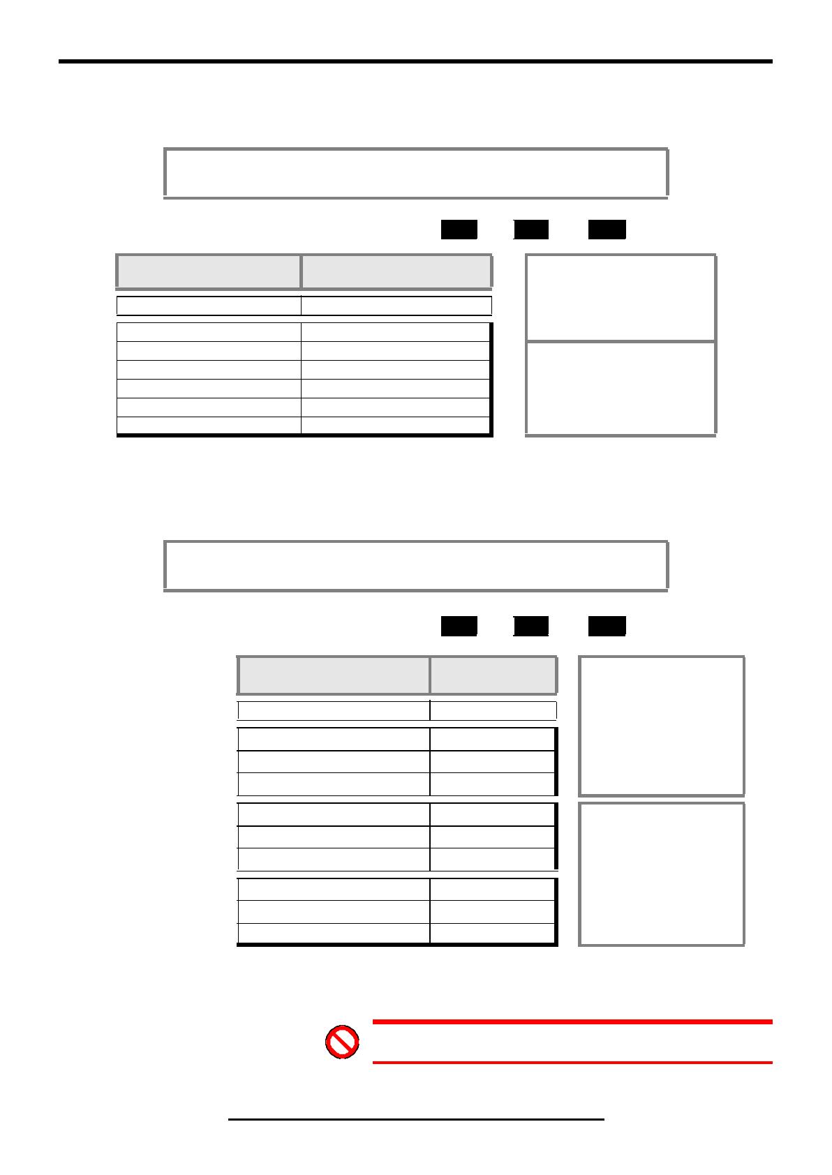
REQUIRED POWER:
1 + 2 = A kW
Rated power (in duty cycle S1) Power supply module
? Until reaching the rated power
demanded from the power supply. All
the required power cannot be supplied,
thus 2 power supplies will be needed.
In kW Reference
If A < 20 RPS-20
If 20 < A < 25 PS-25B4, XPS-25
Very important: When using two power
supplies on the same machine, they must
make up two independent groups with their
own drives. Only the SERCOS® ring (if
there is one) may be common to both
groups.
If 25 < A < 45 RPS-45
If 45 < A < 65 PS-65A, XPS-65
If 65 < A < 75 RPS-75
If A > 75 ?
The power supply module must be capable of supplying the peak power required
(depending on the duty cycles) by the all the motor-drive sets connected to it.
REQUIRED PEAK POWER:
3 + 2 = B
kW
Peak power
(depending on the duty cycle)
Power supply
module
? Until reaching the peak power
demanded from the power supply.
All the required power cannot be
supplied and a second power
supply will be needed.
In kW Reference
NON-REGENERATIVE
POWER SUPPLIES
If B < 75 PS-25B4
If 75 < B < 195 PS-65A
If B > 195 ?
REGENERATIVE
POWER SUPPLIES
If B < 55 XPS-25
Very important: When using
two power supplies on the
same machine, they must
make up two independent
groups with their own drives.
Only the SERCOS® ring (if
there is one) may be common
to both groups.
If 55 < B < 108 XPS-65
If B > 108 ?
REGENERATIVE
REGULATED
POWER SUPPLIES
If B < 26 RPS-20
If 26 < B < 59 RPS-45
If 59 < B < 97 RPS-75
WARNING: Never connect the power supplies in parallel !


