Page is loading ...

Raritan LED KVM Console
(T1700-LED/T1900-LED)
User Guide
Release 1.1
Copyright © 2018 Raritan, Inc.
T1700LED_T1900LED-1C-v1.1-E
October 2018
255-37-0002-00 RoHS

This document contains proprietary information that is protected by copyright. All rights reserved. No
part of this document may be photocopied, reproduced, or translated into another language without
express prior written consent of Raritan, Inc.
© Copyright 2018 Raritan, Inc. All third-party software and hardware mentioned in this document are
registered trademarks or trademarks of and are the property of their respective holders.
FCC Information
This equipment has been tested and found to comply with the limits for a Class A digital device,
pursuant to Part 15 of the FCC Rules. These limits are designed to provide reasonable protection
against harmful interference in a commercial installation. This equipment generates, uses, and can
radiate radio frequency energy and if not installed and used in accordance with the instructions, may
cause harmful interference to radio communications. Operation of this equipment in a residential
environment may cause harmful interference.
VCCI Information (Japan)
Raritan is not responsible for damage to this product resulting from accident, disaster, misuse,
abuse, non-Raritan modification of the product, or other events outside of Raritan's reasonable
control or not arising under normal operating conditions.
If a power cable is included with this product, it must be used exclusively for this product.

Elevated Operating Ambient:
If installed in a closed or multi-unit rack assembly, the operating ambient temperature of the
rack environment may be greater than room ambient. Therefore, consideration should be given to
installing the equipment in an environment compatible with the maximum ambient temperature
(Tma) specified by the manufacturer.
Reduced Air Flow:
Installation of the equipment in a rack should be such that the amount of air flow required for
safe operation of the equipment is not compromised.
Mechanical Loading:
Mounting of the equipment in the rack should be such that a hazardous condition is not achieved
due to uneven mechanical loading.
Circuit Overloading:
Consideration should be given to the connection of the equipment to the supply circuit and the
effect that overloading of the circuits might have on overcurrent protection and supply wiring.
Appropriate consideration of equipment nameplate ratings should be used when addressing this
concern.
Reliable Earthing:
Reliable earthing of rack-mounted equipment should be maintained. Particular attention should
be given to supply connections other than direct connections to the branch circuit (e.g. use of
power strips).
Rack-mount Safety Instructions

iv
Contents
Rack-mount Safety Instructions iii
What's New in the LED KVM Console User Guide vi
Important Safeguards vii
What the Warranty Does Not Cover ................................................................................................vii
Safety Instructions..........................................................................................................................viii
Chapter 1 Introduction 1
Package Content............................................................................................................................... 1
Structure Diagram............................................................................................................................ 2
Chapter 2 Installation 3
Before Installation............................................................................................................................ 3
Installing the LED KVM Console ...................................................................................................... 4
Connecting a Server or KVM Switch ................................................................................................ 7
Connections via VGA and USB or PS/2 .................................................................................. 7
Connections via DVI and USB or PS/2 ................................................................................... 9
Connecting an External USB Device (Optional) ............................................................................. 10
Chapter 3 Operation 12
Locking or Unlocking the LED KVM Console ................................................................................. 12
Operating the LED KVM Console.................................................................................................... 13
Closing the LED KVM Console........................................................................................................ 14
Chapter 4 Using the OSD Menu 15
Onscreen Display Operation........................................................................................................... 15
Onscreen Menu............................................................................................................................... 16
Auto Adjust ........................................................................................................................... 16
Luminance............................................................................................................................ 17
Management ........................................................................................................................ 17
Color..................................................................................................................................... 18
OSD....................................................................................................................................... 19

Contents
v
Language.............................................................................................................................. 19
Recall ................................................................................................................................... 20
Information........................................................................................................................... 20
Selecting the Video Source (Optional)............................................................................................ 21
Appendix A Specifications 22
Technical Specifications................................................................................................................. 22
T1700-LED............................................................................................................................ 22
T1900-LED............................................................................................................................ 24
Environmental Specifications......................................................................................................... 25
Dimensions..................................................................................................................................... 26
Appendix B Ground Screw 27
Appendix C Taiwan BSMI Certification 28
Index 29

vi
The following sections have changed or information has been added to
the LED KVM Console Online Help based on enhancements and changes
to the equipment and/or user documentation.
T1700-LED
(on page 22)
T1900-LED
(on page 23)
Taiwan BSMI Certification
(on page 28)
Ple
ase see the Release Notes for a more detailed explanation of the
changes applied to this version of LED KVM Console.
What's New in the LED KVM Console
User Guide

vii
Read all these instructions carefully before you use the device. Save this
manual for future reference.
What the Warranty Does Not Cover
Any product, on which the serial number has been defaced, modified
or removed.
Damage, deterioration or malfunction resulting from:
Accident, misuse, neglect, fire, water, lightning, or other acts of
nature, unauthorized product modification, or failure to follow
instructions supplied with the product.
Repair or attempted repair by anyone not authorized by us.
Any damage of the product due to shipment.
Removal or installation of the product.
Causes external to the product, such as electric power
fluctuation or failure.
Use of supplies or parts not meeting our specifications.
Normal wear and tear.
Any other causes which does not relate to a product defect.
Removal, installation, and set-up service charges.
Important Safeguards

Chapter 1: Important Safeguards
viii
Safety Instructions
Unplug equipment before cleaning. Don't use liquid or spray
detergent; use a moist cloth.
Keep equipment away from excessive humidity and heat. Preferably,
keep it in an air-conditioned environment with temperatures not
exceeding 40º Celsius (104º Fahrenheit).
When installing, place the equipment on a sturdy, level surface to
prevent it from accidentally falling and causing damage to other
equipment or injury to persons nearby.
When the LCD console is in an open position, do not cover, block or
in any way obstruct the gap between it and the power supply. Proper
air convection is necessary to keep it from overheating.
Arrange the equipment's power cord in such a way that others won't
trip or fall over it.
If you are using a power cord that didn't ship with the equipment,
ensure that it is rated for the voltage and current labeled on the
equipment's electrical ratings label. The voltage rating on the cord
should be higher than the one listed on the equipment's ratings
label.
Observe all precautions and warnings attached to the equipment.
If you don't intend to use the equipment for a long time, disconnect it
from the power outlet to prevent being damaged by transient
over-voltage.
Keep all liquids away from the equipment to minimize the risk of
accidental spillage. Liquid spilled on to the power supply or on other
hardware may cause damage, fire or electrical shock.
Only qualified service personnel should open the chassis. Opening it
yourself could irreparably damage the equipment and invalidate its
warranty.
If any part of the equipment becomes damaged or stops functioning,
have it checked by qualified service personnel.

1
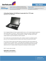
This User Guide introduces Raritan's 1U rackmount LED KVM Consoles:
T1700-LED and T1900-LED, which are used to operate a KVM switch or
server in the data center or server room. A Raritan LED KVM Console
features an
LED-backlit LCD display
and a
DVI port
.
T1700-LED and T1900-LED are functionally identical except for the
following major differences:
T1700-LED uses a 17-inch display while T1900-LED uses a 19-inch
display.
T1700-LED supports the video resolution up to 1920 x 1080 while
T1900-LED supports up to 1280 x 1024.
T1700-LED's screen aspect ratio is 16:9 while T1900-LED's is 4:3.
For more details, see
Technical Specifications
(on page 22).
In This Chapter
Package Content .........................................................................................1
Structure Diagram ......................................................................................2
Package Content
The LED KVM Console comes with standard parts shown below. Check
and make sure they are included and in good condition. If anything is
missing or damaged, contact Raritan or the local vendor immediately.
LED KVM Console
Rackmount brackets
* Mounting depth adjustable from 520 to 908 mm
KVM combo cable (VGA, USB, PS/2)
DVI cable
Quick Setup Guide
Warranty card
Power cord
Drawer key (to unlock the console)
Chapter 1 Introduction

Chapter 1: Introduction
2
Structure Diagram
1. Touchpad
2. Keyboard
3. Indicators for Num Lock, Caps Lock and Scroll Lock status
4. LCD display
5. OSD buttons and indicator lamp
6. Adjustable mounting brackets
7. Ergonomic concave handle
8. Lock

3
In This Chapter
Before Installation.......................................................................................3
Installing the LED KVM Console .................................................................4
Connecting a Server or KVM Switch ...........................................................7
Connecting an External US
B Device (Optional) ........................................10
Before Installation
It is very important to locate this product in a suitable environment.
The surface for placing and fixing this product should be stable and
level or mounted into a suitable cabinet.
Make sure the place has good ventilation, is out of direct sunlight,
away from sources of excessive dust, dirt, heat, water, moisture, and
vibration.
Convenience for connecting this product to related facilities should
be well considered too.
Chapter 2 Installation

Chapter 2: Installation
4
Installing the LED KVM Console
Follow the procedure below to install the LED KVM Console.
To rack-mount the LED KVM Console:
1. Slightly loosen the fasteners on the brackets, adjust the length of the
brackets to match the mounting depth of the rack, and then tighten
the fasteners.

Chapter 2: Installation
5
2. Fasten the brackets to the rack rails securely with your own screws
or cage nuts.
3. Slide the LED KVM Console between the brackets.

Chapter 2: Installation
6
4. Fasten the LED KVM Console to the rack.
The diagram below illustrates how the LED KVM Console moves between
the brackets.

Chapter 2: Installation
7
Connecting a Server or KVM Switch
The LED KVM Console can be connected to either a KVM
(keyboard/video/mouse) switch or a server.
You must always use the Raritan-provided KVM combo cable to make the
connection.
A DVI cable is required if the server's or KVM switch's video port is a DVI
port, or if you prefer using the DVI port.
Connections via VGA and USB or PS/2
You can make a connection to any
VGA-based
server or KVM switch via
VGA and USB or PS/2.
Do NOT connect both USB and PS/2 connectors simultaneously.
Do NOT use a USB-A to USB-B cable for the keyboard and touchpad of
the LED KVM Console.
If connecting Raritan's MCCAT28/216 KVM switch, the LED KVM Console
only supports the PS/2 connection.
Warning: Raritan's MasterConsole II (MCC) KVM switch is NOT
supported so do not connect any MCC device to it.
Server - VGA and USB connection
KVM combo cable
VGA-based server

Chapter 2: Installation
8
Server - VGA and PS/2 connection
KVM switch - VGA and USB connection
KVM combo cable
VGA-based KVM switch
KVM switch - VGA and PS/2 connection

Chapter 2: Installation
9
Connections via DVI and USB or PS/2
You can make a connection to a
DVI-based
server or KVM switch, such as
Raritan's Dominion KX III KVM switch, via a combination of DVI and USB
or PS/2 interface.
Do NOT connect both USB and PS/2 connectors simultaneously.
Do NOT use a USB-A to USB-B cable for the keyboard and touchpad of
the LED KVM Console.
Server - DVI and USB connection
KVM combo cable
DVI cable
DVI-based server
Server - DVI and PS/2 connection

Chapter 2: Installation
10
Tip: If both DVI and VGA ports are available on the server, you may make
connections to both ports, and then press the DOWN/SOURCE button to
switch between different video sources.
KX III KVM switch - DVI and USB connection
KVM combo cable
DVI cable
KX III or any DVI-based KVM
switch with USB ports
Note: If your DVI-based KVM switch provides only PS/2 ports, connect
PS/2 rather than the USB connector of the KVM combo cable to the KVM
switch.
Connecting an External USB Device (Optional)
The LED KVM Console provides an additional USB interface that
functions as the extension of the USB-A interface of the server
connected to it, therefore facilitating the use of an external USB device
with the server, such as a USB keyboard, mouse or a USB disk.
This additional USB interface comprises a USB-B port on the rear panel
of the LED KVM Console and a USB-A port on the front panel. The USB
connection between the server and the LED KVM Console is required in
order to use this USB interface.
To connect an external USB device:
1. Use a regular USB-A to USB-B cable to connect the LED KVM
Console and the server.
a. Plug the USB-A connector into one of the available USB-A ports
on the server.

Chapter 2: Installation
11
b. Plug the USB-B connector into the USB-B port on the rear side
of the LED KVM Console.
Note: Raritan does not provide the USB-A to USB-B cable.
2. Connect any USB device to the front panel USB-A port of the LED
KVM Console.
Now the server should detect the connection of this external USB device.
If necessary, install the driver for the detected USB device.

12
In This Chapter
Locking or Unlocking the LED KVM Console............................................ 12
Operating the LED KVM Console...............................................................13
Closing the LED KVM Console ..................................................................14
Locking or Unlocking the LED KVM Console
The LED KVM Console has a lock to the right side. When locked, you
cannot draw this product out of the rack.
Use the drawer key or a coin-shaped object to turn the lock.
To unlock this product, turn the lock counterclockwise.
To lock this product, turn the lock clockwise.
Chapter 3 Operation
/