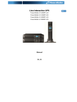
Roline ProSecure II 1000 User manual

Category
Uninterruptible power supplies (UPSs)
Type
User manual
I
ROLINE ProSecure II
700/1000/1500/2000/3000VA
Standgerät
19”Rack 1HE / 2HE
Bedienungsanleitung
III
NETZWERK TRANSIENTEN SCHUTZ 13
BEDIENUNGSLEITFADEN FÜR ANWENDER 14
START UND SHUTDOWN DER USV 14
SHUTDOWN DER USV 14
TASTEN BEDIENUNG 14
KONTROL-PANEL FUNKTIONEN 15
NORMAL-DISPLAY 16
USV KONFIGURATIONEN 16
MANUELLER TEST DER USV 17
ERKLÄRUNG DER USV-MELDUNGEN 18
ALARM ANZEIGEN 18
FEHLERBEHEBUNGEN 19
WARTUNG 19
BATTERIE-WECHSEL 20
BATTERIETAUSCH 20
TECHNISCHE SPEZIFIKATIONEN I
STANDARDS II
ProSecure II
700 VA - 3000 VA UPS
User’s and Installation Manual
1
. IV
INTRODUCTION 7
SYSTEM DESCRIPTION 7
FREE RUN MODE 9
DIAGNOSTIC TESTS 9
SYSTEM CONFIGURATION 10
SAFETY INFORMATION 11
STORAGE 12
INSTALLATION 12
REAR PANEL VIEWS 14
CONNECTION TO MAINS AND LOADS 16
DEFAULT SETTINGS AT THE FACTORY 17
COMPUTER AND ALARM CONNECTIONS 17
CONNECTING THE UPS TO A COMPUTER 17
RS-232 STANDARD INTERFACE PORT 18
USB PORT 18
NETWORK TRANSIENT PROTECTOR 18
LOAD SEGMENTS 18
USER’S GUIDE TO OPERATIONS 19
STARTING AND SHUTTING DOWN THE UPS 19
BUTTON OPERATION 20
CONTROL PANEL FUNCTIONS 20
2
NORMAL DISPLAY 21
UPS CONFIGURATIONS 21
MANUAL TEST OF THE UPS 23
INTERPRETING UPS MESSAGES 23
TROUBLE SHOOTING 24
MAINTENANCE 25
REPLACING BATTERIES 25
TECHNICAL SPECIFICATIONS 26
STANDARDS 27
3
NOTICE: Pursuant to section 15 of the FCC rules, this product has been tested and thereby complies to the conditions of a
Class B (700-2000VA) and Class A (3000VA) digital device, which have been established for offering sufficient protection
against dangerous interference for installation in a residential area. Installation and use of the equipment should comply with
the instructions provided in order to avoid such interference due to the amount of radio frequency energy that is radiated and
generated by the equipment. In spite of this, we cannot assure that a certain amount of interference may not occur in some
installations. If, by turning on and off, it can be deduced that your radio or television reception is found to be influenced by
harmful interference from the equipment, it is recommended to use one of the following preventive measures:
l Place the receiving antenna in a separate location or orientation.
l Ensure a greater distance is achieved between the receiver and the equipment.
l Ensure that your equipment is connected to an outlet on a separate circuit than the receiver.
l Contact a technician experienced with radio and TV or a dealer for further assistance.
This Class B Interference Causing Equipment meets all requirements of the Canadian Interference Causing Equipment
Regulations ICES–003. Cet appareil numérique de la classe B respecte toutes les exigences du Reglement sur le matériel
brouilleur du Canada.
Declaration of Conformity Request
Units labeled with a CE mark comply with the following standards and directives:
l Harmonic Standards: EN 50091-1-1 and EN 50091-2
l EU Directives:73/23/EEC, Council Directive on equipment designed for use within certain voltage limits
93/68/EEC, Amending Directive 73/23/EEC
89/336/EEC, Council Directive relating to electromagnetic compatibility
92/31/EEC, Amending Directive 89/336/EEC relating to EMC
The EC Declaration of Conformity is available upon request for products with a CE mark.
4
IMPORTANT SAFETY INSTRUCTIONS
SAVE THESE INSTRUCTIONS
CAUTION (UPS Having Internal Batteries): Risk of electric shock - Hazardous live parts inside this unit are
energized from the battery supply even when the input AC power is disconnected.
CAUTION (No User serviceable Parts): Risk of electric shock, do not remove cover. No user serviceable parts
inside. Refer servicing to qualified service personnel.
CAUTION (Non-isolated Battery supply): Risk of electric shock, battery circuit is not isolated from AC input,
hazardous voltage may exist between battery terminals and ground. Test before touching.
WARNING (Fuses): To reduce the risk of fire, replace only with the same type and rating of fuse.
WARNING: Intend for installation in a controlled environment.
CAUTION: Do not dispose of batteries in a fire, the battery may explode.
CAUTION: Do not open or mutilate the battery, released electrolyte is harmful to the skin and eyes.
CAUTION: A battery can present a risk of electric shock and high short circuit current. The following
precaution should be observed when working on batteries
Remove watches, rings or other metal objects.
Use tools with insulated handles.
To reduce the risk of electric shock, disconnect the UPS from the mains supply before installing a computer
interface signal cable. Reconnect the powers cord only after signaling interconnections have been
made.Servicing of batteries should be performed or supervised by personnel knowledge of batteries and the
required precautions. Keep unauthorized personnel away from batteries.
5
The instructions contained within this safety manual are deemed important and should be closely
followed at all times during installation and follow-up maintenance of the UPS and batteries.
CAUTION
The unit has a dangerous amount of voltage. If the UPS indicator is on, the unit’s outlets may
have a dangerous
amount of voltage even when not plugged into the wall outlet because the battery may continue
to supply power.
Care should be taken to undertake installation indoors free from electrically-conductive
particles which is under temperature and humidity control in order to reduce
the risk of electric shock.
It is best to disconnect the device using the power supply cord. Ensure that the equipment is
placed in a position near
the outlet where easily accessible.
Except replacing the batteries, all servicing on this equipment must be carried out by qualified
service personnel.
Before conducting any maintenance, repair or shipment, first ensure that everything is turned
off completely and disconnected.
For additional safety instructions, please use the Safety Manual as reference.
6
Special Symbols
The following symbols used on the UPS warn you of precautions:
RISK OF ELECTRIC SHOCK – Please observe the warning that a risk of electric shock is
present.
CAUTION: REFER TO OPERATOR’S MANUAL - Refer to the operator’s manual for
additional information, such as important operating and maintenance instructions.
SAFE GROUNDING TERMINAL - Indicates primary safe ground
LOAD ON/OFF - Pressing this button turns on/off the outputreceptacles and the Indicator light.
RJ-45 RECEPTACLE - The receptacle provides network interface connections and telephone or
telecommunications equipment should not be plugged into it.
Please do not discard the UPS or UPS batteries as the UPS may have valve regulated, lead–acid
batteries. Please recycle batteries.
The instructions contained within this safety manual are deemed important and should be closely
followed at all times during installation and follow-up maintenance of the UPS and batteries.
7
Introduction
The information provided in this manual covers single phase 700 – 3000 VA, uninterruptible power
systems, their basic functions, operating procedures, and emergency situations, also including information
on how to ship, store, handle and install the equipment. Only detailed requirements of the UPS units are
described herein, and installation must be carried out in accordance with this manual. Electrical
installations must also carefully follow local legislation and regulations. Only qualified personnel should
conduct these installations as failure to acknowledge electrical hazards could prove to be fatal.
System description
Several different kinds of sensitive electrical equipment stay protected by a UPS (Uninterruptible Power
System) including computers, workstations, process control systems, telecommunications systems, sales
terminals, other critical instrumentation, etc. The purpose of the UPS is to protect these systems from
poor quality utility power, complete loss of power, or other associated problems.
Electrical interference abounds in many forms causing problems in AC power, from lightning, power
company accidents and radio transmissions to motors, air conditioners, and vending machines, among
others. So protection of sensitive electrical equipment is vital to protect against power outages, low or
high voltage, slow voltage fluctuations, frequency variations, differential and common-mode noises,
transients, etc.
In order to prevent power line problems reaching critical systems causing damage to software, hardware
and causing equipment to malfunction, the UPS helps by maintaining constant voltage, isolating critical
load output if needed, and cleaning the utility AC power.
8
General description
As a double conversion on-line UPS, it is able to supply uninterrupted, clean single-phase power to your
critical systems while keeping batteries charged continuously, regardless of whether utility power fails or
not.
In event that a power failure lasts longer than a UPS backup time, it will shut down avoiding battery
discharge, and as soon as voltage comes back, the UPS will automatically charge up and start recharging
the batteries.
As shown in fig.1 block diagram:
l An input filter reduces transients on the mains
l For maintaining full battery charge, AC-power is rectified and regulated in the rectifier feeding power
to the inverter and battery converter.
l DC power is converted to AC in the inverter passing it on to the load.
l Power is maintained from the battery during a power failure.
l The converter increases voltage appropriately for the inverter.
Fig.1. Block diagram
The Efficiency Optimizer function is a new feature for the UPS adding cost effectiveness, minimizing
power loss and reducing power consumption. Alternating between bypass and on-line modes is achieved
automatically and in accordance with the conditions of the utility power. On-line mode may be used
during times of intermittent power supply, and bypass mode when power flows smoothly in order to
obtain greatest efficiency. Irregularities can be detected in less than a second, and on-line mode
reactivated immediately. Switching back to online mode occurs when input voltage is outside ±10% or
nominal (±15% selectable), when input frequency is outside of ±3Hz or when no input line is available.
Although high efficiency is standard, the default operation is in on-line mode. Bypass can be activated in
the LCD panel, though on-line can be run permanently if preferred.
9
Free Run Mode
The UPS operates in free run mode when input frequency is outside of the selected input frequency range.
Free run mode is when output frequency does not match input frequency. When starting the UPS, the
frequency regulation detected is 50 or 60 Hz ±0.25Hz. Please refer to chapter 7.2 if you want bypass
available while running in free run mode.
Diagnostic tests
When you start the UPS, a diagnostic test is automatically executed that checks electronics, battery, and
reports any problems on the LCD display.
An advanced battery management system always monitors the conditions of the batteries sends any
forewarnings if replacement is needed. Otherwise every 30 days of normal mode operation, a battery
discharge test is performed and any problems reported on the LCD display.
Except during the first 24 hours after startup while the UPS is in charging mode (please see chapter 7.2),
diagnostic tests can be performed manually from the front panel at any time.
10
System Configuration
The UPS device and the internal backup battery make up the system. Depending on the site and load
requirements of the installation, certain additional options are available as a tailored solution.
Planning a UPS system, the following should be taken into consideration:
l The total demand of the protected system shall dictate the output power rating (VA). Allow a margin
for future expansion or calculation inaccuracies from measuring power requirements.
l Backup time needed will indicate the battery size needed. If load is less than the UPS nominal power
rating then actual backup time is longer.
l The following options are available:
l External Battery Cabinets
l Transformer cabinets
l Maintenance bypass switches
l Connectivity options (relay card, SNMP/WEB card)
The following UPS models are available
Model
Backup time
Internal batteries
Recharge time to 90% capacity
UPS 700VA 5 min 4 hours
UPS 1000VA 6 min 4 hours
UPS 1500VA 5 min 4 hours
UPS 2000VA 6 min 4 hours
UPS 3000VA 5 min 4 hours
Additional External Battery Cabinets are available if more back-up time is needed.
11
Safety Information
Information presented here is vital to all personnel and please also read the UPS
safety manual.
Storage and Transportation
Please handle with extreme caution since a high amount of energy is contained with the batteries. Always
keep the unit in position as marked on the packaging and never drop the unit.
Installation
If flammable substances such as gases or fumes are present or if the room is airtight, a safety hazard
situation exists, in which no electrical equipment should be operated.
The instructions in this manual explain how to install the UPS safely. Not acknowledging such electrical
hazards may be fatal, so keep this manual for all future reference.
WARNING!
It is strongly advisable not to open the UPS cabinet as the components have very high voltage
and touching them may be fatal. Only a technician from the manufacturer or an authorized
agent may service the unit.
This UPS unit’s output receptacles carry live voltage even when not connected to a power
supply as it has its own energy source.
User’s operations
The only operations that users are permitted to do are:
l Turning the UPS unit on and off
l Operating the users interface
l Connecting data interface cables
l Changing the batteries
All such operations are to be performed exactly as instructed in this manual. The greatest care possible
must be taken for any of these operations and any change thereof may prove very hazardous to the
operator.
12
Storage
Please adhere to the following instructions if the UPS is not installed immediately:
l Store the equipment as is in its original packing and shipping carton
l Do not store in temperatures outside the range of +15°C to +25°C.
l Ensure that the equipment is fully protected from wet or damp areas and from moist air.
In order to maintain the vitality of the batteries, ensure that the UPS is recharged every 6 months for at
least 8 hours.
Installation
Environment
Ensure that all environmental concerns and requirements are met according to these technical
specifications, otherwise the safety of installation personnel cannot be guaranteed and the unit
may malfunction.
Ensure that you remember the following when locating the UPS system and battery options:
l Avoid extremes of temperature and humidity. Maximal battery life can be attained with a
recommended temperature range of 15 °C to 25 °C.
l Provide protection for the equipment from moisture.
l Space and ventilation requirements must be met. Ensure there is 100mm behind and 50mm on the
sides of the UPS for ventilation.
l Ensure that the front of the UPS remains clear for user operation.
The External Battery Cabinets has to be installed next to the UPS or under the UPS.
13
Installation of “Rack-mounted” types:
Installation with bottom bracket. Installation with rear bracket
14
Rear panel views
PROSECURE II 700~1.5KVA REAR PANEL
PROSECURE II 2-3KVA REAR PANEL
16
Connection to mains and loads
The following Input and Output cables come supplied with all models
700 VA, 1000 VA, (option)- IEC 320 10 A (Input cable)
1500 VA, 2000 VA Two IEC-IEC 320 10 A (Load cable)
3000 VA (option)-IEC 320 16 A (Input cable)
Two IEC-IEC 320 10 A (Load cable)
l Ensure that the UPS is disconnected from mains and loads while connecting the External Battery
Cabinets, if needed.
l Use the battery cable that comes with the External Battery Cabinet to connect the External Battery
Cabinet to the UPS. Connect a second battery cabinet to the first one with the cable provided if more
than one is to be installed.
l Be aware of UPS parameters and changing the Battery pack quantity when using the external battery
cabinets (see chapter 7.2)
l Connect the Input cable to the UPS and connect the other end to a grounded outlet. The batteries will
automatically charge when connected to the mains. Please realize that although you may start using the
UPS immediately, maximum back-up time will still not be available, so it is recommended to charge
the batteries for a minimum of 8 hours before use.
l If unit instantly shows a “Site Wiring Fault”, rotate the connector (Schuko) (see chapter 7.4).
l After charging, connect the loads to the UPS (see the example in fig 3).
l Do not connect any devices that have the possibility of overloading the UPS or drawing half-wave
rectified current, such as hair dryers or vacuum cleaners.
l Should computer or alarm connections be used, use connections according to chapter 6 of the manual
provided with that option. The connections can be referred to on the rear panel.
l The installation is now complete
17
Fig. 3 Example of Installation of Plug & Play products
Default settings at the factory
On the LCD display you will find several of the UPS parameters to select. Default settings are
as follows:
Settings Selection Factory default
100/110/115/120/127
Vac
120V (FOR LV series)
Output Voltage Setting
208/220/230/240 Vac 230V (FOR HV series)
Input/Bypass Voltage
±10%
+10/-15%
+15/-20%
+10/-15%
Input/Frequency
±2%
±5%
±7%
±5%
HE Mode Setting On/Off Off
Free Run Mode On/Off On
Bypass Enable/Disable at free run mode Disable/Enable Disable
Alarm silence On/Off Off
Site wiring alarm Enable/Disable Disable
External Battery pack setting 0, 1, 2 0
You may change default settings, but we recommend that this is done after installation and before starting
up loads. Read UPS configurations in chapter 7.2 for more information.
Computer and Alarm connections
At the back of the UPS is an interface allowing direct communication with your computer system, the location of which can be
found in figure 2. There is a RS232 serial data interface, one USB data interface and an emergency power off switch supplied.
However, the RS232 port cannot be used when the USB interface is in use.
In addition there is an optional interface slot that allows you to install different communications cards. It can be used parallel
with either the RS232 or USB ports.
Currently there are two cards available for the optional interface slot. An SNMP/WEB card allows management and
monitoring over a network or internet, and the AS/400 card allows voltage free relay contacts. Your local dealer will have
more information about these option cards.
Connecting the UPS to a Computer
The communication device for the UPS and PC comes as a complete package with power management
software. Only the communication cable provided with UPS may be used to connect to your computer,
which is accomplished through the UPS RS232 port. Also ensure that the operating system on your
computer is supported. Instructions provided in the power management software will help with this
installation.
Other advanced power protection solutions such as SNMP are provided by your dealer.
18
RS-232 Standard Interface port
The RS-232 interface uses a 9-pin female D-sub connector. This information consists of data about utility, load and the UPS.
The interface port pins and their functions are identified in the following table.
Pin # Signal name Direction (re UPS) Functions
2 TxD Output TxD Output
3 RxD Input RxD / Inverter Off Input
5 Common Common
6 CTS Output Ac Fail Output
8 DCD Output Low Battery Output
9 RI Output +8-24 VDC Power
USB port
Connecting the UPS to your computer is accomplished through the USB port on the back of your
computer. USB compliant hardware and operating system will be necessary including installation of a
UPS driver. The serial port cannot be used when using the USB port. The USB cable is standard and can
be bought separately.
EPO port (emergency power off)
A customer-supplied switch located remotely can be used to open the EPO connection and allows UPS
output receptacles to be switched off. Since the EPO shuts down the equipment immediately, orderly
shutdown procedures are not followed and not by any power management software. The UPS will have to
be manually restarted in order to regain power to the outlets.
Network Transient protector
The network transient protector, located on the back panel, has both IN and OUT jacks, and houses a
single RJ-45 (10BaseT) network connector. Connect the input connector to the jack labeled IN, and the
output connector to the jack labeled OUT.
Load segments
The power management software controls the sets of receptacles known as load segments which provides
organized shutdown and startup of the equipment. Less critical equipment can be turned off during power
outages saving battery power for critical loads. The power management software manual has more details
regarding this. The load group status can be viewed from the LCD display and can be changed if
necessary. These load segments are usually handled with the UPS management software. Refer to chapter
5.2 regarding the two load segments that come with each model.
C
aut
i
on
!
Max rated values
24Vdc/50mA
  • Page 1 1
  • Page 2 2
  • Page 3 3
  • Page 4 4
  • Page 5 5
  • Page 6 6
  • Page 7 7
  • Page 8 8
  • Page 9 9
  • Page 10 10
  • Page 11 11
  • Page 12 12
  • Page 13 13
  • Page 14 14
  • Page 15 15
  • Page 16 16
  • Page 17 17
  • Page 18 18
  • Page 19 19
  • Page 20 20
  • Page 21 21
  • Page 22 22
  • Page 23 23
  • Page 24 24
  • Page 25 25
  • Page 26 26
  • Page 27 27
  • Page 28 28
  • Page 29 29
  • Page 30 30
  • Page 31 31
  • Page 32 32
  • Page 33 33
  • Page 34 34
  • Page 35 35
  • Page 36 36
  • Page 37 37
  • Page 38 38
  • Page 39 39
  • Page 40 40
  • Page 41 41
  • Page 42 42
  • Page 43 43
  • Page 44 44
  • Page 45 45
  • Page 46 46
  • Page 47 47
  • Page 48 48
  • Page 49 49
  • Page 50 50
  • Page 51 51
  • Page 52 52
  • Page 53 53
  • Page 54 54
  • Page 55 55
  • Page 56 56
  • Page 57 57
  • Page 58 58

Roline ProSecure II 1000 User manual

Category
Uninterruptible power supplies (UPSs)
Type
User manual

Ask a question and I''ll find the answer in the document

Finding information in a document is now easier with AI

in other languages