Page is loading ...


DynaDip| Hybrid Insert Secure Card Reader Authenticator | Installation and Operation Manual
Page 2 of 34 (D998200432-10)
Copyright © 2006 - 2020 MagTek, Inc.
Printed in the United States of America
INFORMATION IN THIS PUBLICATION IS SUBJECT TO CHANGE WITHOUT NOTICE AND
MAY CONTAIN TECHNICAL INACCURACIES OR GRAPHICAL DISCREPANCIES. CHANGES
OR IMPROVEMENTS MADE TO THIS PRODUCT WILL BE UPDATED IN THE NEXT
PUBLICATION RELEASE. NO PART OF THIS DOCUMENT MAY BE REPRODUCED OR
TRANSMITTED IN ANY FORM OR BY ANY MEANS, ELECTRONIC OR MECHANICAL, FOR
ANY PURPOSE, WITHOUT THE EXPRESS WRITTEN PERMISSION OF MAGTEK, INC.
MagTek®, MagnePrint®, and MagneSafe® are registered trademarks of MagTek, Inc.
Magensa™ is a trademark of MagTek, Inc.
AAMVA™ is a trademark of AAMVA.
American Express® and EXPRESSPAY FROM AMERICAN EXPRESS® are registered trademarks of
American Express Marketing & Development Corp.
D-PAYMENT APPLICATION SPECIFICATION® is a registered trademark to Discover Financial
Services CORPORATION
MasterCard® is a registered trademark and PayPass™ and Tap & Go™ are trademarks of MasterCard
International Incorporated.
Visa® and Visa payWave® are registered trademarks of Visa International Service Association.
ANSI®, the ANSI logo, and numerous other identifiers containing "ANSI" are registered trademarks,
service marks, and accreditation marks of the American National Standards Institute (ANSI).
ISO® is a registered trademark of the International Organization for Standardization.
UL™ and the UL logo are trademarks of UL LLC.
PCI Security Standards Council® is a registered trademark of the PCI Security Standards Council, LLC.
EMV® is a registered trademark in the U.S. and other countries and an unregistered trademark elsewhere.
The EMV trademark is owned by EMVCo, LLC. The Contactless Indicator mark, consisting of four
graduating arcs, is a trademark owned by and used with permission of EMVCo, LLC.
Google Play™ store, Google Wallet™ payment service, and Android™ platform are trademarks of
Google Inc.
Apple Pay®, iPhone®, iPod®, Mac®, and OS X® are registered trademarks of Apple Inc., registered in
the U.S. and other countries. iPad™ is a trademark of Apple. Inc. App Store
SM
is a service mark of
Apple Inc., registered in the U.S. and other countries. IOS is a trademark or registered trademark of
Cisco in the U.S. and other countries and is used by Apple Inc. under license.
Microsoft®, Windows®, and .NET® are registered trademarks of Microsoft Corporation.
All other system names and product names are the property of their respective owners.

DynaDip| Hybrid Insert Secure Card Reader Authenticator | Installation and Operation Manual
Page 3 of 34 (D998200432-10)
Table 0-1 - Revisions
Rev Number
Date
Notes
10
Aug 17, 2020
Initial Release

DynaDip| Hybrid Insert Secure Card Reader Authenticator | Installation and Operation Manual
Page 4 of 34 (D998200432-10)
LIMITED WARRANTY
MagTek warrants that the products sold pursuant to this Agreement will perform in accordance with
MagTek’s published specifications. This warranty shall be provided only for a period of one year from
the date of the shipment of the product from MagTek (the “Warranty Period”). This warranty shall apply
only to the “Buyer” (the original purchaser, unless that entity resells the product as authorized by
MagTek, in which event this warranty shall apply only to the first repurchaser).
During the Warranty Period, should this product fail to conform to MagTek’s specifications, MagTek
will, at its option, repair or replace this product at no additional charge except as set forth below. Repair
parts and replacement products will be furnished on an exchange basis and will be either reconditioned or
new. All replaced parts and products become the property of MagTek. This limited warranty does not
include service to repair damage to the product resulting from accident, disaster, unreasonable use,
misuse, abuse, negligence, or modification of the product not authorized by MagTek. MagTek reserves
the right to examine the alleged defective goods to determine whether the warranty is applicable.
Without limiting the generality of the foregoing, MagTek specifically disclaims any liability or warranty
for goods resold in other than MagTek’s original packages, and for goods modified, altered, or treated
without authorization by MagTek.
Service may be obtained by delivering the product during the warranty period to MagTek (1710 Apollo
Court, Seal Beach, CA 90740). If this product is delivered by mail or by an equivalent shipping carrier,
the customer agrees to insure the product or assume the risk of loss or damage in transit, to prepay
shipping charges to the warranty service location, and to use the original shipping container or equivalent.
MagTek will return the product, prepaid, via a three (3) day shipping service. A Return Material
Authorization (“RMA”) number must accompany all returns. Buyers may obtain an RMA number by
contacting MagTek Support Services at (888) 624-8350.
EACH BUYER UNDERSTANDS THAT THIS MAGTEK PRODUCT IS
OFFERED AS-IS. MAGTEK MAKES NO OTHER WARRANTY, EXPRESS OR
IMPLIED, AND MAGTEK DISCLAIMS ANY WARRANTY OF ANY OTHER
KIND, INCLUDING ANY WARRANTY OF MERCHANTABILITY OR FITNESS
FOR A PARTICULAR PURPOSE.
IF THIS PRODUCT DOES NOT CONFORM TO MAGTEK’S
SPECIFICATIONS, THE SOLE REMEDY SHALL BE REPAIR OR
REPLACEMENT AS PROVIDED ABOVE. MAGTEK’S LIABILITY, IF ANY,
SHALL IN NO EVENT EXCEED THE TOTAL AMOUNT PAID TO MAGTEK
UNDER THIS AGREEMENT. IN NO EVENT WILL MAGTEK BE LIABLE TO
THE BUYER FOR ANY DAMAGES, INCLUDING ANY LOST PROFITS, LOST
SAVINGS, OR OTHER INCIDENTAL OR CONSEQUENTIAL DAMAGES
ARISING OUT OF THE USE OF, OR INABILITY TO USE, SUCH PRODUCT,
EVEN IF MAGTEK HAS BEEN ADVISED OF THE POSSIBILITY OF SUCH
DAMAGES, OR FOR ANY CLAIM BY ANY OTHER PARTY.

DynaDip| Hybrid Insert Secure Card Reader Authenticator | Installation and Operation Manual
Page 5 of 34 (D998200432-10)
LIMITATION ON LIABILITY
EXCEPT AS PROVIDED IN THE SECTIONS RELATING TO MAGTEK’S LIMITED WARRANTY,
MAGTEK’S LIABILITY UNDER THIS AGREEMENT IS LIMITED TO THE CONTRACT PRICE OF
THIS PRODUCT.
MAGTEK MAKES NO OTHER WARRANTIES WITH RESPECT TO THE PRODUCT, EXPRESSED
OR IMPLIED, EXCEPT AS MAY BE STATED IN THIS AGREEMENT, AND MAGTEK
DISCLAIMS ANY IMPLIED WARRANTY, INCLUDING WITHOUT LIMITATION ANY IMPLIED
WARRANTY OF MERCHANTABILITY OR FITNESS FOR A PARTICULAR PURPOSE.
MAGTEK SHALL NOT BE LIABLE FOR CONTINGENT, INCIDENTAL, OR CONSEQUENTIAL
DAMAGES TO PERSONS OR PROPERTY. MAGTEK FURTHER LIMITS ITS LIABILITY OF ANY
KIND WITH RESPECT TO THE PRODUCT, INCLUDING NEGLIGENCE ON ITS PART, TO THE
CONTRACT PRICE FOR THE GOODS.
MAGTEK’S SOLE LIABILITY AND BUYER’S EXCLUSIVE REMEDIES ARE STATED IN THIS
SECTION AND IN THE SECTION RELATING TO MAGTEK’S LIMITED WARRANTY.

DynaDip| Hybrid Insert Secure Card Reader Authenticator | Installation and Operation Manual
Page 6 of 34 (D998200432-10)
FCC INFORMATION
This device complies with Part 15 of the FCC Rules. Operation is subject to the following two
conditions: (1) This device may not cause harmful interference, and (2) This device must accept any
interference received, including interference that may cause undesired operation.
Note: This equipment has been tested and found to comply with the limits for a Class B digital device,
pursuant to part 15 of the FCC Rules. These limits are designed to provide reasonable protection against
harmful interference in a residential installation. This equipment generates, uses and can radiate radio
frequency energy and, if not installed and used in accordance with the instructions, may cause harmful
interference to radio communications. However, there is no guarantee that interference will not occur in a
particular installation. If this equipment does cause harmful interference to radio or television reception,
which can be determined by turning the equipment off and on, the user is encouraged to try to correct the
interference by one or more of the following measures:
Reorient or relocate the receiving antenna.
Increase the separation between the equipment and receiver.
Connect the equipment into an outlet on a circuit different from that to which the receiver is
connected.
Consult the dealer or an experienced radio/TV technician for help.
Caution: Changes or modifications not expressly approved by MagTek could void the
user’s authority to operate this equipment.
CE STANDARDS
Testing for compliance with CE requirements was performed by an independent laboratory. The unit
under test was found compliant with standards established for Class B devices.
UL/CSA/CUR/UR
This product is recognized per UL 60950-1, 2nd Edition, 2011-12-19 (Information Technology
Equipment - Safety - Part 1: General Requirements), CSA C22.2 No. 60950-1-07, 2nd Edition,
2011-12 (Information Technology Equipment - Safety - Part 1: General Requirements).
ROHS STATEMENT
When ordered as RoHS compliant, this product meets the Electrical and Electronic Equipment (EEE)
Reduction of Hazardous Substances (RoHS) European Directive 2002/95/EC. The marking is clearly
recognizable, either as written words like “Pb-free,” “lead-free,” or as another clear symbol ( ).

0 - Table of Contents
DynaDip| Hybrid Insert Secure Card Reader Authenticator | Installation and Operation Manual
Page 7 of 34 (D998200432-10)
Table of Contents
Limited Warranty .............................................................................................................................................. 4
FCC Information ................................................................................................................................................ 6
CE STANDARDS ................................................................................................................................................. 6
UL/CSA/CUR/UR ............................................................................................................................................... 6
RoHS STATEMENT ............................................................................................................................................. 6
Table of Contents .............................................................................................................................................. 7
1 Introduction ............................................................................................................................................... 9
1.1 Engineering Easier Solutions .......................................................................................................... 9
1.2 Delivering Flexible Solutions .......................................................................................................... 9
1.3 Key Features ..................................................................................................................................... 9
1.4 Built for Easier Integration .............................................................................................................. 9
1.5 The Next Generation of Security .................................................................................................... 9
1.6 DynaDip Paired with DynaWave .................................................................................................. 10
1.7 About DynaDip Components ........................................................................................................ 11
1.8 About Terminology ......................................................................................................................... 12
1.9 About Solution Planning................................................................................................................ 13
1.10 Handling ....................................................................................................................................... 15
2 Electrical Integration .............................................................................................................................. 16
2.1 Overview........................................................................................................................................... 16
2.2 About the Connectors .................................................................................................................... 17
2.3 Grounding / ESD Protection ......................................................................................................... 18
2.4 Shielding and Conditioning ........................................................................................................... 19
3 Mechanical Integration .......................................................................................................................... 20
3.1 Overview........................................................................................................................................... 20
3.2 Dimensions ..................................................................................................................................... 21
3.3 Orientation ....................................................................................................................................... 23
3.4 Panel Cutout.................................................................................................................................... 24
3.5 Mounting .......................................................................................................................................... 25
3.6 Cabling ............................................................................................................................................. 27
3.7 Miscellaneous Considerations...................................................................................................... 28
4 Operation ................................................................................................................................................. 29
4.1 Card Reading / Transactions ........................................................................................................ 29
4.2 About the General Status LED ...................................................................................................... 29
5 Maintenance ............................................................................................................................................ 30
5.1 Mechanical Maintenance .............................................................................................................. 30
5.2 Updates to Firmware, Documentation, Security Guidance...................................................... 30
6 Developing Host Software ..................................................................................................................... 31
Appendix A Technical Specifications ....................................................................................................... 32

0 - Table of Contents
DynaDip| Hybrid Insert Secure Card Reader Authenticator | Installation and Operation Manual
Page 8 of 34 (D998200432-10)

1 - Introduction
DynaDip| Hybrid Insert Secure Card Reader Authenticator | Installation and Operation Manual
Page 9 of 34 (D998200432-10)
1 Introduction
1.1 Engineering Easier Solutions
DynaDip makes upgrading your magnetic stripe reading solution easier. Using the same basic form-
factor and bezels as our P-Series secure card reader authenticator (SCRA), we have added contact EMV
chip card reading technology without adding to the overall device footprint or changing its mounting
points. Now both card reading devices connect to the host as one logical device over USB. If you want
to add contactless card reading, DynaWave can also be connected to offer the most advanced payment
acceptance technology in a small form-factor.
1.2 Delivering Flexible Solutions
Unattended kiosks, vending, parking garages, car wash establishments, ATMs, and fuels pumps can
benefit from this cost-effective solution. DynaDip combines a 3-track magnetic stripe secure card reader
authenticator with contact EMV chip card reading in a small form-factor. Add the contactless EMV /
NFC capability with DynaWave, and you have one of the most secure and flexible hybrid card reading
solutions in the market today.
1.3 Key Features
DynaDip is easy to install and configure, and has key features that include:
USB interface allows for easy to use plug-n-play connectivity
Optional separate NFC module connected to Auxiliary UART port
Available with flat or extended bezel options
1.4 Built for Easier Integration
DynaDip is supported with a variety of software developer kits (SDKs), application program interfaces
(APIs), and Magensa Web Services that make integration easier and more secure. Magensa delivers the
developer tools, browser and middleware applications, and remote services for configuration and key
injection that make the integration process smoother and bring your solution to market faster. MagTek
hardware, coupled with Magensa Services, delivers a powerful and cost-effective solution that can help
you meet your PCI requirements.
1.5 The Next Generation of Security
DynaDip is equipped with the next generation of the MagneSafe Security Architecture. The MagneSafe
Security Architecture has evolved exponentially from its inception in 2006 when it delivered the
industry’s first secure card reader authenticator for secure electronic transactions. The MSA is a digital
identification and authentication architecture that safeguards personal data. Designed to exceed PCI
regulations, MSA leverages strong encryption, secure tokenization, counterfeit detection, tamper
recognition, data relevance and integrity, and dynamic digital transaction signatures, which together
validate and protect the entire transaction and each of its components. DynaDip EMV chip reader is
EMV L1 and L2 certified and the magnetic stripe secure card reader authenticator leverages industry
standard TDEA encryption with DUKPT key management. Security and Certification Features include:
EMV L1 and L2
Data Protection Triple DEA Encryption
DUKPT Key Management
MagneSafe Security Architecture
Unique, Non-Changeable Device Serial Number
MagnePrint® Card Authentication

1 - Introduction
DynaDip| Hybrid Insert Secure Card Reader Authenticator | Installation and Operation Manual
Page 10 of 34 (D998200432-10)
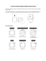
1.6 DynaDip Paired with DynaWave
DynaDip is Modular. Made to work with MagTek components, DynaDip works with DynaWave NFC
module as an added component.

1 - Introduction
DynaDip| Hybrid Insert Secure Card Reader Authenticator | Installation and Operation Manual
Page 11 of 34 (D998200432-10)
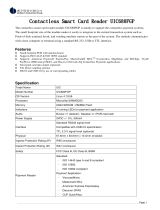
1.7 About DynaDip Components
Figure 1-1 - DynaDip Major Components

1 - Introduction
DynaDip| Hybrid Insert Secure Card Reader Authenticator | Installation and Operation Manual
Page 12 of 34 (D998200432-10)
1.8 About Terminology
In this document, DynaDip is referred to as the device. It is designed to be connected to a host, which is
a piece of general-purpose electronic equipment which can send commands and data to, and receive data
from, the device. Host types include PC computers/laptops, tablets, and smartphones. Generally, the host
must have software installed that communicates with the device and is capable of processing
transactions. During a transaction, the host and its software interact with the operator, such as a cashier
or bank teller, while the device interacts with the cardholder.

1 - Introduction
DynaDip| Hybrid Insert Secure Card Reader Authenticator | Installation and Operation Manual
Page 13 of 34 (D998200432-10)
1.9 About Solution Planning
A smooth deployment of a solution that integrates DynaDip requires some up-front planning and
decision-making:
Determine the overall functional requirements and desired user experience of the solution
DynaDip will be integrated into.
Determine what documentation and training will be required from solution design through testing
and field deployment.
Determine what type of host DynaDip will connect to. When planning, include any additional
support or devices required by the host and its connection, such as physical locations, mounting, and
power connections.
Determine what auxiliary devices DynaDip will connect to. Solutions can add DynaWave for
contactless transactions using the UART port.
Determine which model of DynaDip the solution will include, and what accessories you need. Table
1-1 provides a list of available devices, auxiliary devices, and accessories.
Determine what software will be installed on the host and how it will be configured. Software can
include operating system, transaction processing software, security software, and so on. Include any
additional support required by the software, such as network connections.
Determine how DynaDip should be configured, and specify that when you order devices. MagTek or
your reseller can advise. For deep detail about configuration options and how they affect device
behavior, see D998200151 mDynamo Programmer’s Manual (COMMANDS).
Determine how the solution design will integrate DynaDip electrically (see section 2 Electrical
Integration for details).
Determine how the solution design will integrate DynaDip mechanically (see section 3 Mechanical
Integration for details).
Determine how the solution will be tested and, if appropriate, how it will be certified.
Develop an installation procedure. Installing technicians will need solution-specific materials. In
addition, technicians may be supported by incorporating a Maintenance Mode into the host software
for configuration, updates, and diagnostic tests.
Determine how the solution will be maintained. See section 5 Maintenance for guidance on
maintaining the DynaDip portion of the solution.
Determine how the solution will be regularly inspected. Proper inspection will require solution-
specific training, instructions, and visual references for inspecting the entire solution for tampering,
unauthorized added components such as eavesdropping or skimming devices, and so on.

1 - Introduction
DynaDip| Hybrid Insert Secure Card Reader Authenticator | Installation and Operation Manual
Page 14 of 34 (D998200432-10)
Table 1-1 - Available Accessories
Part Number
Description
21079835
DYNADIP FLAT BEZEL
21079838
DYNADIP EXTENDED BEZEL
21079823
DYNAWAVE, USB, UART
21079834
DYNAWAVE, USB, UART, LOW PROFILE
21079844
DYNADIP, ANGLE BRACKET KIT FOR EXTENDED BEZEL
21051548
CABLE, USB-A TO MICRO USB B 5.4MM PLUG, BLACK, 6FT
96700004
CLEANING CARD, DOUBLE SIDED

1 - Introduction
DynaDip| Hybrid Insert Secure Card Reader Authenticator | Installation and Operation Manual
Page 15 of 34 (D998200432-10)
1.10 Handling
Proper handling of the device throughout delivery, assembly, shipping, installation, usage,
and maintenance is very important. Not following the guidelines in this document could
damage the device, render it inoperable, and/or violate the conditions of the warranty.
From device delivery through assembly, shipping, installation, usage, and maintenance, the device must
not be exposed to conditions outside the ratings in Appendix A Technical Specifications.
If the device is exposed to cold temperatures, adjust it to warmer temperatures gradually to avoid
condensation, which can interfere with the operation of the device or cause permanent damage.
Upon receiving the device, inspect it to make sure it originated from an authentic source and has not been
tampered with.
Do not drop or shake the device.
The device should be transported/stored inside an anti-static bag at all times.
Before removing the device from the package, remove any static charge from your body by touching an
earth-grounded metal surface.
Avoid touching the exposed pins on the connectors when handling the device.
For information about ongoing maintenance of the device, such as cleaning, see section 5 Maintenance.

2 - Electrical Integration
DynaDip| Hybrid Insert Secure Card Reader Authenticator | Installation and Operation Manual
Page 16 of 34 (D998200432-10)
2 Electrical Integration
2.1 Overview
This section provides information and guidelines for designing the electrical aspects of a solution that
incorporates DynaDip. MagTek strongly recommends vetting and testing solution designs before
finalizing and deploying them, to make sure the design meets all requirements (e.g., functional, legal,
security, certification, safety, and so on).
When designing a solution that incorporates DynaDip, consider the following:
Review section 1.7 About DynaDip Components for an overall introduction to the device’s physical
features and what they are called.
Review Appendix A Technical Specifications to make sure the device is suitable for the solution.
Review safe handling practices in section 1.10 Handling to make sure the logistical aspects of the
solution design meet the device’s handling requirements.
Develop solution-specific installation procedures and training materials before distribution to
installation technicians.
Review section 5 Maintenance and develop a maintenance procedure and schedule. When installed
in the solution-specific enclosure, the device may require additional maintenance not covered in the
general guidelines provided here.
Review any additional requirements from other agencies, such as PCI certification requirements,
building codes, and so on, which may introduce additional constraints to the solution design.

2 - Electrical Integration
DynaDip| Hybrid Insert Secure Card Reader Authenticator | Installation and Operation Manual
Page 17 of 34 (D998200432-10)
2.2 About the Connectors
DynaDip provides the following connections (see Figure 1-1 - DynaDip Major Components):
A USB Device port, labeled J3 on the printed circuit board, must be connected directly to a host’s
USB port, or connected to the host via a powered USB hub, to provide power to the device and
bidirectional communication with the host. The device’s USB connector is a Micro-USB B
receptacle designed to mate with a standard Micro-USB B connector found on the peripheral end of
commercially available cables. MagTek does not support connecting multiple DynaDip devices
simultaneously to the same host. Depending on usage, the device expects to draw up to 500mA at 5V
from the USB port, and the solution design must ensure 500mA is available to the device at all times.
The mDynamo controller board in DynaDip draws a maximum of 300mA, and draws additional
current to drive devices connected to the Auxiliary UART port and the Auxiliary SPI port.
An Auxiliary SPI port, labeled J7 and SPI on the printed circuit board, which is already connected
to the integrated SPI Encrypted IntelliHead with MagneSafe V5. It is a 10-pin 1.25mm pitch Molex
PicoBlade header designed to mate with Molex PicoBlade connector 51021-1000. The dot on the
printed circuit board indicates pin 1. Depending on usage, the auxiliary SPI port can provide up to
100mA @ 3.3V to power an external SPI device.
An Auxiliary UART port, labeled J8 and UART on the printed circuit board, which can be used to
integrate DynaWave and add support for contactless payments. It is a 10-pin 1.25mm pitch Molex
PicoBlade header designed to mate with Molex PicoBlade connector 51021-1000. The dot on the
printed circuit board indicates pin 1. Depending on usage, the Auxiliary UART port can provide up
to 400mA @ 5V to power an external UART device. For details about integrating DynaWave for
contactless transactions, see D998200265 DynaWave Installation and Operation Manual.
An LED connector, labeled J2 and LED on the printed circuit board, which is connected to the LED
integrated into the device’s bezel. It is a 4-pin 1.25mm pitch Molex PicoBlade header designed to
mate with Molex PicoBlade connector 51021-0410. The dot printed on the circuit board indicates
pin 1. The connector provides 3.3V up to 24 mA. The device can be configured to drive J2 to match
the General Status LED on DynaDip’s mDynamo controller board (see section 4.2 About the
General Status LED). However, custom software on the host may override the External LED
behavior.

2 - Electrical Integration
DynaDip| Hybrid Insert Secure Card Reader Authenticator | Installation and Operation Manual
Page 18 of 34 (D998200432-10)
2.3 Grounding / ESD Protection
To guard against ground loops and to protect the device against electrostatic discharge (ESD), it is
important for the solution design to ground the device correctly. MagTek strongly recommends checking
whether the host’s USB port provides earth ground, and whether the selected USB cable carries that
ground all the way to the shield of USB port [J3] on the device’s board. This will help make an informed
decision about proper grounding. There are two paths to provide earth ground to the device; MagTek
recommends all solution designs bring in earth ground to the device using one and only one of the
possible paths:
Bring in earth ground from the host through the USB cable’s metal connector shell to the USB Device
Port [J3]
Bring in earth ground through the Alternate Earth Grounding Standoff. See Figure 2-1 for details.
Figure 2-1 - Using the Alternate Earth Grounding Standoff
After deciding which point will be grounded, make sure none of the remaining ground points are
connected to a different ground.
In addition, solutions that incorporate devices with a metal bezel must ground the bezel to the same earth
ground potential as the point chosen above. This provides an additional path to protect the device from
electrostatic discharge during card insertion and provides additional protection for the device’s
electronics. MagTek recommends this earth grounding cable comprise 18AWG stranded wires.

2 - Electrical Integration
DynaDip| Hybrid Insert Secure Card Reader Authenticator | Installation and Operation Manual
Page 19 of 34 (D998200432-10)
2.4 Shielding and Conditioning
MagTek recommends using shielded cables to provide noise immunity and to prevent radiated emissions.
The device itself has been tested by an FCC lab for Class B radiated susceptibility and has no special
shielding requirements. For details, see the FCC information provided at the beginning of this document.
MagTek also recommends that all communication cabling (i.e., USB) should be draped together where
possible, and isolated from any unrelated earth ground cables and other wiring nearby that could
potentially couple noise into the device. In addition, MagTek recommends keeping any possible noise
sources away from the SPI IntelliHead cables to avoid interfering with the low-level MagnePrint head
signals.
The device has no special requirements for power conditioning or signal conditioning.

3 - Mechanical Integration
DynaDip| Hybrid Insert Secure Card Reader Authenticator | Installation and Operation Manual
Page 20 of 34 (D998200432-10)
3 Mechanical Integration
3.1 Overview
This section provides information and guidelines for designing the mechanical aspects of a solution that
incorporates DynaDip. MagTek strongly recommends vetting and testing solution designs before
finalizing and deploying them, to make sure the design meets all requirements (e.g., functional, legal,
security, certification, safety, and so on).
When designing the mechanical portions of a solution that incorporates DynaDip, consider the following:
Review section 1.7 About DynaDip Components for an overall introduction to the device’s physical
features and what they are called.
Review Appendix A Technical Specifications to make sure the device is suitable for the solution.
See section 3.2 Dimensions for overall device dimensions.
Determine device orientation. Options and constraints are provided in section 3.3 Orientation.
Design the solution enclosure front panel. Information about fitting the device into a panel cutout are
in section 3.4 Panel Cutout. When designing, make sure there is adequate clearance around the card
insertion slot to insert a card, and make sure to consider any additional factors for other integrated
devices, such as DynaWave (for details, see D998200265 DynaWave Installation and Operation
Manual).
Determine how the device will be mounted. See section 3.5 Mounting for details. Coordinate with
the electrical design team to make sure the panel design, mounting hardware, and solution-specific
installation instructions meet electrical requirements.
Coordinate with the electrical design team to plan cable routing and fastening. See section 3.6
Cabling for details.
Consider additional factors that do not fit these categories. See section 3.7 Miscellaneous
Considerations.
Review safe handling practices in section 1.10 Handling to make sure the logistical aspects of the
solution design meet the device’s handling requirements.
Develop solution-specific installation procedures and training materials before distribution to
installation technicians.
Review section 5 Maintenance and develop a maintenance procedure and schedule. When installed
in the solution-specific enclosure, the device may require additional maintenance not covered in the
general guidelines provided here.
Review any additional requirements from other agencies, such as PCI certification requirements,
building codes, and so on, which may introduce additional constraints to the solution design.
/