Page is loading ...


mDynamo| EMV Contact Reader / Transaction Hub Module | Installation and Operation Manual
Page 2 of 27 (D998200144-14)
Copyright © 2006 - 2021 MagTek, Inc.
Printed in the United States of America
INFORMATION IN THIS PUBLICATION IS SUBJECT TO CHANGE WITHOUT NOTICE AND
MAY CONTAIN TECHNICAL INACCURACIES OR GRAPHICAL DISCREPANCIES. CHANGES
OR IMPROVEMENTS MADE TO THIS PRODUCT WILL BE UPDATED IN THE NEXT
PUBLICATION RELEASE. NO PART OF THIS DOCUMENT MAY BE REPRODUCED OR
TRANSMITTED IN ANY FORM OR BY ANY MEANS, ELECTRONIC OR MECHANICAL, FOR
ANY PURPOSE, WITHOUT THE EXPRESS WRITTEN PERMISSION OF MAGTEK, INC.
MagTek® is a registered trademark of MagTek, Inc.
MagnePrint® is a registered trademark of MagTek, Inc.
Magensa™ is a trademark of MagTek, Inc.
MagneSafe™ is a trademark of MagTek, Inc.
Molex® is a registered trademark and PicoBlade™ is a trademark of Molex, its affiliates, related
companies, licensors, and/or joint venture partners.
MasterCard® is a registered trademark of MasterCard International Incorporated.
ISO® is a registered trademark of the International Organization for Standardization.
EMVCo™ and EMV™ are trademarks of EMVCo and its licensors.
UL™ and the UL logo are trademarks of UL LLC.
Android™ is a trademark of Google Inc.
Mac®, and OS X® are registered trademarks of Apple Inc., registered in the U.S. and other countries.
IOS is a trademark or registered trademark of Cisco in the U.S. and other countries and is used by Apple
Inc. under license.
Microsoft® and Windows® are registered trademarks of Microsoft Corporation.
All other system names and product names are the property of their respective owners.
Table 0-1 - Revisions
Rev Number
Date
Notes
10
Dec 23, 2016
Initial Release
11
Mar 3, 2017
Add cable part numbers, connectable heads; to planning section
1.10, add key management and encrypting options; misc.
clarifications
12
Sep 7, 2017
Clarify separation of function between on-board General Status
LED in section 4.2 and the External LED Connector [J2], add
callout of on-board general status LED in section 1.8
13
Oct 2, 2017
Production release
14
Feb 4, 2021
Update temperature ranges in Appendix A to reflect latest
design and tests; Update styles and doc standards.

mDynamo| EMV Contact Reader / Transaction Hub Module | Installation and Operation Manual
Page 3 of 27 (D998200144-14)
LIMITED WARRANTY
MagTek warrants that the products sold pursuant to this Agreement will perform in accordance with
MagTek’s published specifications. This warranty shall be provided only for a period of one year from
the date of the shipment of the product from MagTek (the “Warranty Period”). This warranty shall apply
only to the “Buyer” (the original purchaser, unless that entity resells the product as authorized by
MagTek, in which event this warranty shall apply only to the first repurchaser).
During the Warranty Period, should this product fail to conform to MagTek’s specifications, MagTek
will, at its option, repair or replace this product at no additional charge except as set forth below. Repair
parts and replacement products will be furnished on an exchange basis and will be either reconditioned or
new. All replaced parts and products become the property of MagTek. This limited warranty does not
include service to repair damage to the product resulting from accident, disaster, unreasonable use,
misuse, abuse, negligence, or modification of the product not authorized by MagTek. MagTek reserves
the right to examine the alleged defective goods to determine whether the warranty is applicable.
Without limiting the generality of the foregoing, MagTek specifically disclaims any liability or warranty
for goods resold in other than MagTek’s original packages, and for goods modified, altered, or treated
without authorization by MagTek.
Service may be obtained by delivering the product during the warranty period to MagTek (1710 Apollo
Court, Seal Beach, CA 90740). If this product is delivered by mail or by an equivalent shipping carrier,
the customer agrees to insure the product or assume the risk of loss or damage in transit, to prepay
shipping charges to the warranty service location, and to use the original shipping container or equivalent.
MagTek will return the product, prepaid, via a three (3) day shipping service. A Return Material
Authorization (“RMA”) number must accompany all returns. Buyers may obtain an RMA number by
contacting MagTek Support Services at (888) 624-8350.
EACH BUYER UNDERSTANDS THAT THIS MAGTEK PRODUCT IS
OFFERED AS-IS. MAGTEK MAKES NO OTHER WARRANTY, EXPRESS OR
IMPLIED, AND MAGTEK DISCLAIMS ANY WARRANTY OF ANY OTHER
KIND, INCLUDING ANY WARRANTY OF MERCHANTABILITY OR FITNESS
FOR A PARTICULAR PURPOSE.
IF THIS PRODUCT DOES NOT CONFORM TO MAGTEK’S
SPECIFICATIONS, THE SOLE REMEDY SHALL BE REPAIR OR
REPLACEMENT AS PROVIDED ABOVE. MAGTEK’S LIABILITY, IF ANY,
SHALL IN NO EVENT EXCEED THE TOTAL AMOUNT PAID TO MAGTEK
UNDER THIS AGREEMENT. IN NO EVENT WILL MAGTEK BE LIABLE TO
THE BUYER FOR ANY DAMAGES, INCLUDING ANY LOST PROFITS, LOST
SAVINGS, OR OTHER INCIDENTAL OR CONSEQUENTIAL DAMAGES
ARISING OUT OF THE USE OF, OR INABILITY TO USE, SUCH PRODUCT,
EVEN IF MAGTEK HAS BEEN ADVISED OF THE POSSIBILITY OF SUCH
DAMAGES, OR FOR ANY CLAIM BY ANY OTHER PARTY.

mDynamo| EMV Contact Reader / Transaction Hub Module | Installation and Operation Manual
Page 4 of 27 (D998200144-14)
LIMITATION ON LIABILITY
EXCEPT AS PROVIDED IN THE SECTIONS RELATING TO MAGTEK’S LIMITED WARRANTY,
MAGTEK’S LIABILITY UNDER THIS AGREEMENT IS LIMITED TO THE CONTRACT PRICE OF
THIS PRODUCT.
MAGTEK MAKES NO OTHER WARRANTIES WITH RESPECT TO THE PRODUCT, EXPRESSED
OR IMPLIED, EXCEPT AS MAY BE STATED IN THIS AGREEMENT, AND MAGTEK
DISCLAIMS ANY IMPLIED WARRANTY, INCLUDING WITHOUT LIMITATION ANY IMPLIED
WARRANTY OF MERCHANTABILITY OR FITNESS FOR A PARTICULAR PURPOSE.
MAGTEK SHALL NOT BE LIABLE FOR CONTINGENT, INCIDENTAL, OR CONSEQUENTIAL
DAMAGES TO PERSONS OR PROPERTY. MAGTEK FURTHER LIMITS ITS LIABILITY OF ANY
KIND WITH RESPECT TO THE PRODUCT, INCLUDING NEGLIGENCE ON ITS PART, TO THE
CONTRACT PRICE FOR THE GOODS.
MAGTEK’S SOLE LIABILITY AND BUYER’S EXCLUSIVE REMEDIES ARE STATED IN THIS
SECTION AND IN THE SECTION RELATING TO MAGTEK’S LIMITED WARRANTY.

mDynamo| EMV Contact Reader / Transaction Hub Module | Installation and Operation Manual
Page 5 of 27 (D998200144-14)
FCC WARNING STATEMENT
This equipment has been tested and found to comply with the limits for a Class B digital device, pursuant
to part 15 of the FCC Rules. These limits are designed to provide reasonable protection against harmful
interference in a residential installation. This equipment generates, uses and can radiate radio frequency
energy and, if not installed and used in accordance with the instructions, may cause harmful interference
to radio communications. However, there is no guarantee that interference will not occur in a particular
installation. If this equipment does cause harmful interference to radio or television reception, which can
be determined by turning the equipment off and on, the user is encouraged to try to correct the
interference by one or more of the following measures:
Reorient or relocate the receiving antenna.
Increase the separation between the equipment and receiver.
Connect the equipment to an outlet on a different circuit than the receiver.
Consult the dealer or an experienced radio/TV technician for help.
FCC COMPLIANCE STATEMENT
This device complies with Part 15 of the FCC Rules. Operation of this device is subject to the following
two conditions: (1) This device may not cause harmful interference, and (2) This device must accept any
interference received, including interference that may cause undesired operation.
CUR/UR
This product is recognized per Underwriter Laboratories and Canadian Underwriter Laboratories 1950.
CE STANDARDS
Testing for compliance with CE requirements was performed by an independent laboratory. The unit
under test was found compliant with standards established for Class B devices.
UL/CSA
This product is recognized per Underwriter Laboratories and Canadian Underwriter Laboratories 1950.
ROHS STATEMENT
When ordered as RoHS compliant, this product meets the Electrical and Electronic Equipment (EEE)
Reduction of Hazardous Substances (RoHS) European Directive 2002/95/EC. The marking is clearly
recognizable, either as written words like “Pb-free,” “lead-free,” or as another clear symbol ( ).

mDynamo| EMV Contact Reader / Transaction Hub Module | Installation and Operation Manual
Page 6 of 27 (D998200144-14)
SOFTWARE LICENSE AGREEMENT
IMPORTANT: YOU SHOULD CAREFULLY READ ALL THE TERMS, CONDITIONS AND
RESTRICTIONS OF THIS LICENSE AGREEMENT BEFORE INSTALLING THE SOFTWARE
PACKAGE. YOUR INSTALLATION OF THE SOFTWARE PACKAGE PRESUMES YOUR
ACCEPTANCE OF THE TERMS, CONDITIONS, AND RESTRICTIONS CONTAINED IN THIS
AGREEMENT. IF YOU DO NOT AGREE WITH THESE TERMS, CONDITIONS, AND
RESTRICTIONS, PROMPTLY RETURN THE SOFTWARE PACKAGE AND ASSOCIATED
DOCUMENTATION TO THE ADDRESS ON THE FRONT PAGE OF THIS DOCUMENT,
ATTENTION: CUSTOMER SUPPORT.
TERMS, CONDITIONS, AND RESTRICTIONS
MagTek, Incorporated (the "Licensor") owns and has the right to distribute the described software and
documentation, collectively referred to as the "Software."
LICENSE: Licensor grants you (the "Licensee") the right to use the Software in conjunction with
MagTek products. LICENSEE MAY NOT COPY, MODIFY, OR TRANSFER THE SOFTWARE IN
WHOLE OR IN PART EXCEPT AS EXPRESSLY PROVIDED IN THIS AGREEMENT. Licensee
may not decompile, disassemble, or in any other manner attempt to reverse engineer the Software.
Licensee shall not tamper with, bypass, or alter any security features of the software or attempt to do so.
TRANSFER: Licensee may not transfer the Software or license to the Software to another party without
the prior written authorization of the Licensor. If Licensee transfers the Software without authorization,
all rights granted under this Agreement are automatically terminated.
COPYRIGHT: The Software is copyrighted. Licensee may not copy the Software except for archival
purposes or to load for execution purposes. All other copies of the Software are in violation of this
Agreement.
TERM: This Agreement is in effect as long as Licensee continues the use of the Software. The Licensor
also reserves the right to terminate this Agreement if Licensee fails to comply with any of the terms,
conditions, or restrictions contained herein. Should Licensor terminate this Agreement due to Licensee's
failure to comply, Licensee agrees to return the Software to Licensor. Receipt of returned Software by
the Licensor shall mark the termination.
LIMITED WARRANTY: Licensor warrants to the Licensee that the disk(s) or other media on which
the Software is recorded are free from defects in material or workmanship under normal use.
THE SOFTWARE IS PROVIDED AS IS. LICENSOR MAKES NO OTHER WARRANTY OF ANY
KIND, EITHER EXPRESS OR IMPLIED, INCLUDING, BUT NOT LIMITED TO, THE IMPLIED
WARRANTIES OF MERCHANTABILITY AND FITNESS FOR A PARTICULAR PURPOSE.
Because of the diversity of conditions and PC hardware under which the Software may be used, Licensor
does not warrant that the Software will meet Licensee specifications or that the operation of the Software
will be uninterrupted or free of errors.
IN NO EVENT WILL LICENSOR BE LIABLE FOR ANY DAMAGES, INCLUDING ANY LOST
PROFITS, LOST SAVINGS, OR OTHER INCIDENTAL OR CONSEQUENTIAL DAMAGES
ARISING OUT OF THE USE, OR INABILITY TO USE, THE SOFTWARE. Licensee's sole remedy in
the event of a defect in material or workmanship is expressly limited to replacement of the Software
disk(s) if applicable.

mDynamo| EMV Contact Reader / Transaction Hub Module | Installation and Operation Manual
Page 7 of 27 (D998200144-14)
GOVERNING LAW: If any provision of this Agreement is found to be unlawful, void, or
unenforceable, that provision shall be removed from consideration under this Agreement and will not
affect the enforceability of any of the remaining provisions. This Agreement shall be governed by the
laws of the State of California and shall inure to the benefit of MagTek, Incorporated, its successors or
assigns.
ACKNOWLEDGMENT: LICENSEE ACKNOWLEDGES THAT HE HAS READ THIS
AGREEMENT, UNDERSTANDS ALL OF ITS TERMS, CONDITIONS, AND RESTRICTIONS, AND
AGREES TO BE BOUND BY THEM. LICENSEE ALSO AGREES THAT THIS AGREEMENT
SUPERSEDES ANY AND ALL VERBAL AND WRITTEN COMMUNICATIONS BETWEEN
LICENSOR AND LICENSEE OR THEIR ASSIGNS RELATING TO THE SUBJECT MATTER OF
THIS AGREEMENT.
QUESTIONS REGARDING THIS AGREEMENT SHOULD BE ADDRESSED IN WRITING TO
MAGTEK, INCORPORATED, ATTENTION: CUSTOMER SUPPORT, AT THE ADDRESS LISTED
IN THIS DOCUMENT, OR E-MAILED TO SUPPORT@MAGTEK.COM.

0 - Table of Contents
mDynamo| EMV Contact Reader / Transaction Hub Module | Installation and Operation Manual
Page 8 of 27 (D998200144-14)
Table of Contents
Table of Contents .............................................................................................................................................. 8
1 Introduction ............................................................................................................................................... 9
1.1 About mDynamo .............................................................................................................................. 9
1.2 Simple Integration............................................................................................................................ 9
1.3 Contact Chip Card............................................................................................................................. 9
1.4 Security .............................................................................................................................................. 9
1.5 Magensa Services ............................................................................................................................ 9
1.6 Fast Development ............................................................................................................................ 9
1.7 USB Options ...................................................................................................................................... 9
1.8 About mDynamo Components ..................................................................................................... 10
1.9 About Terminology ......................................................................................................................... 10
1.10 About Solution Planning ........................................................................................................... 11
2 Electrical Integration .............................................................................................................................. 12
2.1 Grounding / ESD Protection ......................................................................................................... 12
2.2 Shielding .......................................................................................................................................... 13
2.3 About Signal Connectors ............................................................................................................... 13
2.4 USB Port [J3] ................................................................................................................................... 13
2.5 Auxiliary UART Port [J8] ................................................................................................................. 14
2.6 Auxiliary SPI Port [J7] .................................................................................................................... 15
2.7 External LED Connector [J2] ......................................................................................................... 16
3 Mechanical Integration .......................................................................................................................... 17
3.1 Enclosure Design ............................................................................................................................ 18
3.2 Cabling Design ................................................................................................................................ 21
4 Operation ................................................................................................................................................. 22
4.1 Card Reading / Transactions ........................................................................................................ 22
4.2 About the General Status LED ...................................................................................................... 23
5 Developing Custom Software ............................................................................................................... 24
Appendix A Technical Specifications ....................................................................................................... 25

1 - Introduction
mDynamo| EMV Contact Reader / Transaction Hub Module | Installation and Operation Manual
Page 9 of 27 (D998200144-14)
1 Introduction
This document provides suggestions, guidelines, and technical information for designing solutions that
integrate mDynamo, MagTek’s modular contact chip card reader for OEM solutions.
1.1 About mDynamo
mDynamo gives users the flexibility to add a variety of identification and payment acceptance options
from a compact, modular design. The small form-factor makes it easy to integrate into new or existing
unattended locations including kiosks, vending, parking, or payment terminals; and is an ideal solution for
mobile payment applications involving tablets and phones to accept payments almost anywhere. The card
reading module is easy to incorporate into an enclosure. mDynamo is engineered to save the integration
designer money in a single, low-cost, yet highly secure device.
1.2 Simple Integration
Using an updated bezel, mDynamo can be added to a new design or, if only magnetic stripe is being used,
retrofitted to existing insertion style magnetic stripe readers. The chip card reader and optional NFC
module are certified for EMV L1 and L2. MagTek offers a variety of software developer kits (SDKs) to
use with Windows, iOS, and Android operating systems.
1.3 Contact Chip Card
mDynamo is an affordable and flexible card reading module. It is designed to read contact chip cards that
conform to ISO 7816 standards. mDynamo supports a variety of connection options that can support
additional card reading technologies, including magnetic stripe readers/SCRAs and contactless/NFC
modules. The board is well designed for a compact footprint while offering easily accessible SPI and
UART ports with Molex connectors.
1.4 Security
mDynamo is built on the MagneSafe Security Architecture (MSA). When coupled with MagTek’s
Magensa services, MagnePrint magnetic stripe card authentication can be activated to stop fraud and the
use of altered cards. mDynamo uses TDES encryption and DUKPT key management to protect card data.
1.5 Magensa Services
mDynamo is supported by the full suite of Magensa's Services: Data decryption, card and device
authentication, gateway, device configuration, and key injection. MagTek provides well-defined and
documented web services and several off-the-shelf applications for reader configuration on Windows,
iOS, and Android platforms.
1.6 Fast Development
Invest in mDynamo and receive dedicated software, hardware, and payments support. Working with
MagTek OEM is the fastest way to secure, compliant, flexible payment solutions for your custom device.
1.7 USB Options
The primary communications interface is USB. mDynamo is powered over USB so there is no need for
additional cabling or external power supplies.

1 - Introduction
mDynamo| EMV Contact Reader / Transaction Hub Module | Installation and Operation Manual
Page 10 of 27 (D998200144-14)
1.8 About mDynamo Components
Figure 1-1 – mDynamo Major Components
1.9 About Terminology
In this document, mDynamo is referred to as the device. It is designed to be connected to a host, which is
a piece of general-purpose electronic equipment which can send commands and data to, and receive data
from, the device. Host types include PC computers/laptops, tablets, and smartphones. Generally, the host
must have software installed that communicates with the device and is capable of processing
transactions. The combination of device(s), host(s), software, firmware, configuration settings, physical
mounting and environment, user experience, and documentation is referred to as the solution. During a
transaction, the host and its software interact with the operator, such as a cashier or bank teller, while the
device interacts with the cardholder.

1 - Introduction
mDynamo| EMV Contact Reader / Transaction Hub Module | Installation and Operation Manual
Page 11 of 27 (D998200144-14)
1.10 About Solution Planning
A smooth deployment of a solution that integrates mDynamo requires some up-front planning and
decision-making:
Determine the overall functional requirements and desired user experience of the solution
mDynamo will be integrated into.
Determine what documentation and training will be required from solution design to deployment.
Determine what type of host mDynamo will connect to. This can be a computer with a fully-powered
USB port. When planning, include any additional support or devices required by the host, such as
physical locations, mounting, and power connections.
Determine what auxiliary devices mDynamo will connect to. Solutions can include external
magnetic stripe readers using UART or SPI protocols, or external contactless NFC readers using the
UART protocol. Table 1-1 provides a list of available auxiliary devices and accessories.
Determine what software will be installed on the host and how it will be configured. Software can
include operating system, transaction processing software, security software, and so on. Include any
additional support required by the software, such as network connections.
Determine how mDynamo should be configured, and specify that when you order devices. MagTek
or your reseller can advise. For deep detail about configuration options and how they affect device
behavior, see D998200151 mDynamo Programmer’s Reference (COMMANDS). For example:
Decide whether mDynamo should be in non-encrypting mode (“Security Level 2”) or encrypting
mode (“Security Level 3” or higher).
Decide on the solution’s key management scheme. The device can be configured either to use
DUKPT key management, or to rely on the host software to manage Fixed Keys.
Determine how the solution design will integrate mDynamo electrically (see section 2 Electrical
Integration for details).
Determine how the solution design will integrate mDynamo mechanically (see section 3 Mechanical
Integration for details).
Determine how the solution design will be tested and, if appropriate, how it will be certified.
Table 1-1 - Available Accessories
Part Number
Description
Related To
21030150
MGSFCO MAGSAFE TDES DUKPT UART
63.5MMWRE/5PMLX
Auxiliary UART Port [J8]
1000003957
CABLE, HEAD EXTENSION, 5 PIN TO 10 PIN,
MDYNAMO
Auxiliary UART Port [J8]
21030088
MGSFCO 3TK INTHD BF-SPR 125MM 8PMLX
SPI MAGSAF V5
Auxiliary SPI Port [J7]
100003958
CABLE, HEAD EXTENSION, 8 PIN TO 10 PIN,
MDYNAMO
Auxiliary SPI Port [J7]

2 - Electrical Integration
mDynamo| EMV Contact Reader / Transaction Hub Module | Installation and Operation Manual
Page 12 of 27 (D998200144-14)
2 Electrical Integration
2.1 Grounding / ESD Protection
Figure 2-1 – mDynamo Chassis Ground Points
Figure 2-1 shows red highlights on all points on mDynamo that share a common earth ground plane:
The four mounting screw pads
The housing of USB Port [J3]
Pin 10 of Auxiliary SPI Port [J7]
Pin 10 of Auxiliary UART Port [J8]
To guard against ground loops and to protect the chip card contact block against electrostatic discharge
(ESD), it is important to ground the device correctly. MagTek strongly recommends checking whether
the host provides earth ground on its USB port shield, and whether the selected USB cable carries that
ground all the way to the shield of USB Port [J3] on the board. This will help make an informed
decision about proper grounding:
If the solution design, including the host, provides earth ground to the shield of USB Port [J3], no
additional ground connections are necessary.
If the solution design does not provide earth ground to the shield of USB Port [J3], the solution
design should connect one or more of the other points in Figure 2-1 to a common chassis ground.
Ideally the chosen ground would be earth ground, because only an earth ground connection provides
ESD protection.
After deciding which points will be grounded, make sure none of the remaining ground points in
Figure 2-1 are connected to a different ground. For example, carefully trace from Pin 10 of the
auxiliary ports through any connected devices to make sure they do not lead to different grounds.

2 - Electrical Integration
mDynamo| EMV Contact Reader / Transaction Hub Module | Installation and Operation Manual
Page 13 of 27 (D998200144-14)
2.2 Shielding
MagTek recommends using earth-grounded shielded cables. The device itself has been tested by an FCC
lab for Class B radiated susceptibility and has no special shielding requirements. For details, see the FCC
information provided at the beginning of this document.
2.3 About Signal Connectors
mDynamo provides the following signal connections:
A USB port, labeled J3 on the printed circuit board, must be connected to a host’s fully-powered
USB port to provide power to the device and bidirectional communication with the host. For details,
see section 2.4 USB Port.
An Auxiliary UART port, labeled J8 and UART on the printed circuit board, can be used to connect
to an optional external contactless module or UART Encrypting IntelliHead with MagneSafe V5. For
details, see section 2.5 Auxiliary UART Port.
An Auxiliary SPI port, labeled J7 and SPI on the printed circuit board, can be used to connect to an
optional external SPI Encrypting IntelliHead with MagneSafe V5. For details, see section 2.6
Auxiliary SPI Port.
An LED connector, labeled J2 and LED on the printed circuit board, can be used in solution designs
that need to provide an external status LED. For details, see section 2.7 External LED Connector.
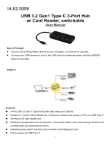
2.4 USB Port [J3]
The USB port, labeled J3 on the printed circuit board, must be directly connected to a host’s fully-
powered USB port to provide power to the device and bidirectional communication with the host. It is a
Micro-USB B receptacle designed to mate with a standard Micro-USB B connector found on
commercially available USB cables. Pinouts are shown in Figure 2-2. MagTek does not support
connecting multiple mDynamo devices simultaneously to the same host.
Figure 2-2 - Pinouts for mDynamo USB Port J3
Depending on usage, the device expects to draw up to 500mA at 5V from the USB port. The device itself
draws a maximum of 300mA and will draw additional current to drive devices connected to the Auxiliary
UART port and the Auxiliary SPI port.

2 - Electrical Integration
mDynamo| EMV Contact Reader / Transaction Hub Module | Installation and Operation Manual
Page 14 of 27 (D998200144-14)
2.5 Auxiliary UART Port [J8]
The Auxiliary UART port, labeled J8 and UART on the printed circuit board, can be used to connect an
optional external contactless module or UART Encrypting IntelliHead with MagneSafe V5. It is a 10-pin
1.25mm pitch Molex PicoBlade header designed to mate with Molex PicoBlade connector 51021-1000.
The dot on the printed circuit board indicates pin 1. Pinouts are shown in Figure 2-3.
Figure 2-3 - Pinouts for mDynamo Auxiliary UART Port J8
Depending on usage, the Auxiliary UART port can provide up to 400mA @ 5V to power an external
UART device.
For details about integrating an NFC contactless module or UART Encrypting IntelliHead with
MagneSafe V5, see the Installation and Operation Manual or Technical Reference Manual for the
module you plan to connect. Programmers should see section 5 Developing Custom Software for cross-
references to programming tools and documentation for communicating through the port.

2 - Electrical Integration
mDynamo| EMV Contact Reader / Transaction Hub Module | Installation and Operation Manual
Page 15 of 27 (D998200144-14)
2.6 Auxiliary SPI Port [J7]
The Auxiliary SPI port, labeled J7 and SPI on the printed circuit board, can be used for connecting to an
optional external SPI Encrypting IntelliHead with MagneSafe V5. It is a 10-pin 1.25mm pitch Molex
PicoBlade header designed to mate with Molex PicoBlade connector 51021-1000. The dot on the printed
circuit board indicates pin 1. Pinouts are shown in Figure 2-4.
Figure 2-4 - Pinouts for mDynamo Auxiliary SPI Port J7
Depending on usage, the auxiliary SPI port can provide up to 100mA @ 3.3V to power an external SPI
device.
For details about connecting to an SPI Encrypting IntelliHead with MagneSafe V5, see the Installation
and Operation Manual or Technical Reference Manual for the module you plan to connect. Wiring
specifications for SPI heads are shown in Table 2-1. Programmers should see section 5 Developing
Custom Software for cross-references to programming tools and documentation for communicating
through the port.
Table 2-1 - Connector Pin Specifications for SPI Device Cable
SPI Signal
Color
Connector Pin
SCL
BLUE
1
SDO
YELLOW
2
SDI
RED
3
DAV
BROWN
4
CS
GREEN
5
VIN
WHITE
6
GND
BLACK
7
CASE
VIOLET
8

2 - Electrical Integration
mDynamo| EMV Contact Reader / Transaction Hub Module | Installation and Operation Manual
Page 16 of 27 (D998200144-14)
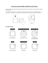
2.7 External LED Connector [J2]
The External LED connector, labeled J2 and LED on the printed circuit board, can be used to drive an
external LED. It is a 4-pin 1.25mm pitch Molex PicoBlade header designed to mate with Molex
PicoBlade connector 51021-0410. The dot printed on the circuit board indicates pin 1. Pinouts of the
connector, and a reference design for the green portion of the LED connector, are shown in Figure 2-5.
Figure 2-5 – Pinouts and Green LED Reference Implementation for mDynamo LED Connector J2
The connector can drive either an encapsulated red/green three-pin LED with common cathode (allowing
for amber blending) or separate red and green LEDs. The connector provides 3.3V up to 24 mA. Each
LED should have a current-limiting resistor connected in series, with values calculated as R=[(3.3V -
V
LED
) / I
LED
] Ohms, where V
LED
is the characteristic voltage drop across the LED (typically 2V) and I
LED
is optimally between 10mA and 20mA. Solutions that incorporate amber should carefully select and test
current limiting LED resistor values that provide a proper mix that doesn’t look too green or too red.
By default, the device drives J2 to match the General Status LED (see section 4.2 About the General
Status LED). However, custom software on the host the device is connected to may override the
External LED behavior.

3 - Mechanical Integration
mDynamo| EMV Contact Reader / Transaction Hub Module | Installation and Operation Manual
Page 17 of 27 (D998200144-14)
3 Mechanical Integration
Figure 3-1 - mDynamo Overall Mechanical Dimensions in Inches [mm]
Figure 3-2 - mDynamo Detail Mechanical Dimensions in Inches [mm]

3 - Mechanical Integration
mDynamo| EMV Contact Reader / Transaction Hub Module | Installation and Operation Manual
Page 18 of 27 (D998200144-14)
3.1 Enclosure Design
The device should always be placed in an enclosure to protect the device and to guide inexperienced
cardholders in proper usage. Consider the following when designing the enclosure:
Overall dimensions of the device are shown in Figure 3-1. The printed circuit board is 1/32” thick.
Detailed dimensions are shown in Figure 3-2.
The device will work in any orientation, but MagTek recommends a horizontal orientation with the
large stainless steel plate facing the floor to meet cardholder expectations of inserting cards with the
chip facing the ceiling (see Figure 3-3). Consider including visual features on the enclosure to guide
cardholders to insert contact chip cards properly.
Figure 3-3 - mDynamo Recommended Orientation
On request, MagTek can provide a 3D model of the device’s envelope to assist with the mechanical
portion of solution design. MagTek recommends building 3D-printed prototypes with samples before
finalizing the solution design.
The mounting hole placements are provided in Figure 3-2. MagTek suggests stainless steel screws
starting with sizes 0-80 or M1.6, mated with threaded inserts in the enclosure. Make sure mounting
hardware in contact with the mounting holes conforms to grounding requirements in section 2
Electrical Integration.
Enclosure materials should meet UL rating 94 V-0. Examples include polycarbonate/ABS blends,
ABS, polycarbonate, and polypropylene.
The device is designed to withstand insertion forces up to 10N. To provide additional support, the
enclosure may incorporate features that buttress the chip card reader housing.
Be sure to provide at least 1/16 inch (1.5 mm) clearance from the large stainless steel plate of the chip
card reader housing to any portion of the enclosure to allow for soldering variations in different
boards (see reference clearance in Figure 3-2).
The enclosure should have a card slot that aligns with the device’s chip card insertion slot. The
enclosure’s card slot should accommodate cards conforming to ISO 7816: Figure 3-4, Figure 3-5,
and Figure 3-6 provide a reference card slot design to use as a starting point; features of the reference
design include adequate clearance to avoid cards hitting the sides, top, and bottom of the mDynamo
slot, and a cutout on one side of the slot to accommodate embossing on cards.

3 - Mechanical Integration
mDynamo| EMV Contact Reader / Transaction Hub Module | Installation and Operation Manual
Page 19 of 27 (D998200144-14)
Figure 3-4 - Reference Enclosure, Card Slot Width
Figure 3-5 - Reference Enclosure, Card Slot Height and Width

3 - Mechanical Integration
mDynamo| EMV Contact Reader / Transaction Hub Module | Installation and Operation Manual
Page 20 of 27 (D998200144-14)
Figure 3-6 - Reference Enclosure, Card Slot Height
If the solution will use External LED Connector [J2], allow space to run the cable and to mount the
LED(s) to be visible to cardholders during use. For details, see section 2.7 External LED
Connector [J2] and section 4.2 About the General Status LED.
If the solution will use Auxiliary SPI Port [J7] or Auxiliary UART Port [J8] to connect mDynamo
to external UART or SPI modules, allow space to for the connectors and cables, and consider how the
external devices will be mounted relative to the contact chip card insertion slot.
The device operates on low power, so no special cooling should be necessary.
mDynamo is not a PCI certified device; solutions that integrate it should consider how cardholder
data will be secured and which certifications the solution will need to pass.
MagTek strongly recommends testing solution designs before deployment, to make sure they meet all
requirements (e.g., functional, legal, security, certification, safety).
/