Page is loading ...


DynaWave| OEM Contactless NFC Module | Installation and Operation Manual
Page 2 of 38 (D998200265-12)
Copyright © 2006 – 2020 MagTek, Inc.
Printed in the United States of America
INFORMATION IN THIS PUBLICATION IS SUBJECT TO CHANGE WITHOUT NOTICE AND
MAY CONTAIN TECHNICAL INACCURACIES OR GRAPHICAL DISCREPANCIES. CHANGES
OR IMPROVEMENTS MADE TO THIS PRODUCT WILL BE UPDATED IN THE NEXT
PUBLICATION RELEASE. NO PART OF THIS DOCUMENT MAY BE REPRODUCED OR
TRANSMITTED IN ANY FORM OR BY ANY MEANS, ELECTRONIC OR MECHANICAL, FOR
ANY PURPOSE, WITHOUT THE EXPRESS WRITTEN PERMISSION OF MAGTEK, INC.
MagTek® is a registered trademark of MagTek, Inc.
MagnePrint® is a registered trademark of MagTek, Inc.
MagneSafe® is a registered trademark of MagTek, Inc.
Magensa™ is a trademark of MagTek, Inc.
AAMVA™ is a trademark of AAMVA.
American Express® and EXPRESSPAY FROM AMERICAN EXPRESS® are registered trademarks of
American Express Marketing & Development Corp.
D-PAYMENT APPLICATION SPECIFICATION® is a registered trademark to Discover Financial
Services CORPORATION
MasterCard® is a registered trademark and PayPass™ and Tap & Go™ are trademarks of MasterCard
International Incorporated.
Visa® and Visa payWave® are registered trademarks of Visa International Service Association.
ANSI®, the ANSI logo, and numerous other identifiers containing "ANSI" are registered trademarks,
service marks, and accreditation marks of the American National Standards Institute (ANSI).
EMV® is a registered trademark in the U.S. and other countries and an unregistered trademark elsewhere.
The EMV trademark is owned by EMVCo, LLC. The Contactless Indicator mark, consisting of four
graduating arcs, is a trademark owned by and used with permission of EMVCo, LLC.
ISO® is a registered trademark of the International Organization for Standardization.
UL™ and the UL logo are trademarks of UL LLC.
Google Play™ store and Android™ platform are trademarks of Google Inc.
Samsung Pay® is a registered trademark of Samsung Electronics Co., Ltd.
Apple Pay®, OS X®, iPod touch®, iPhone®, iPod®, and Mac® are registered trademarks of Apple Inc.,
registered in the U.S. and other countries. App Store
SM
is a service mark of Apple Inc., registered in the
U.S. and other countries. iPad™ and iPad mini™ are trademarks of Apple, Inc. IOS is a trademark or
registered trademark of Cisco in the U.S. and other countries and is used by Apple Inc. under license.
Microsoft® and Windows® are registered trademarks of Microsoft Corporation.
Microsoft®, Windows® and .NET® are registered trademarks of Microsoft Corporation.
All other trademarks, system names, product names, and trade names are the property of their respective
owners.

DynaWave| OEM Contactless NFC Module | Installation and Operation Manual
Page 3 of 38 (D998200265-12)
Table 0-1 - Revisions
Rev Number
Date
Notes
10
Sep 26, 2018
Initial release
11
Mar 14, 2019
Section 3.7 add extreme temperature considerations
12
June 17, 2020
Updated figure 3-3 with new cut out dimensions

DynaWave| OEM Contactless NFC Module | Installation and Operation Manual
Page 4 of 38 (D998200265-12)
LIMITED WARRANTY
MagTek warrants that the products sold pursuant to this Agreement will perform in accordance with
MagTek’s published specifications. This warranty shall be provided only for a period of one year from
the date of the shipment of the product from MagTek (the “Warranty Period”). This warranty shall apply
only to the “Buyer” (the original purchaser, unless that entity resells the product as authorized by
MagTek, in which event this warranty shall apply only to the first repurchaser).
During the Warranty Period, should this product fail to conform to MagTek’s specifications, MagTek
will, at its option, repair or replace this product at no additional charge except as set forth below. Repair
parts and replacement products will be furnished on an exchange basis and will be either reconditioned or
new. All replaced parts and products become the property of MagTek. This limited warranty does not
include service to repair damage to the product resulting from accident, disaster, unreasonable use,
misuse, abuse, negligence, or modification of the product not authorized by MagTek. MagTek reserves
the right to examine the alleged defective goods to determine whether the warranty is applicable.
Without limiting the generality of the foregoing, MagTek specifically disclaims any liability or warranty
for goods resold in other than MagTek’s original packages, and for goods modified, altered, or treated
without authorization by MagTek.
Service may be obtained by delivering the product during the warranty period to MagTek (1710 Apollo
Court, Seal Beach, CA 90740). If this product is delivered by mail or by an equivalent shipping carrier,
the customer agrees to insure the product or assume the risk of loss or damage in transit, to prepay
shipping charges to the warranty service location, and to use the original shipping container or equivalent.
MagTek will return the product, prepaid, via a three (3) day shipping service. A Return Material
Authorization (“RMA”) number must accompany all returns. Buyers may obtain an RMA number by
contacting MagTek Support Services at (888) 624-8350.
EACH BUYER UNDERSTANDS THAT THIS MAGTEK PRODUCT IS
OFFERED AS-IS. MAGTEK MAKES NO OTHER WARRANTY, EXPRESS OR
IMPLIED, AND MAGTEK DISCLAIMS ANY WARRANTY OF ANY OTHER
KIND, INCLUDING ANY WARRANTY OF MERCHANTABILITY OR FITNESS
FOR A PARTICULAR PURPOSE.
IF THIS PRODUCT DOES NOT CONFORM TO MAGTEK’S
SPECIFICATIONS, THE SOLE REMEDY SHALL BE REPAIR OR
REPLACEMENT AS PROVIDED ABOVE. MAGTEK’S LIABILITY, IF ANY,
SHALL IN NO EVENT EXCEED THE TOTAL AMOUNT PAID TO MAGTEK
UNDER THIS AGREEMENT. IN NO EVENT WILL MAGTEK BE LIABLE TO
THE BUYER FOR ANY DAMAGES, INCLUDING ANY LOST PROFITS, LOST
SAVINGS, OR OTHER INCIDENTAL OR CONSEQUENTIAL DAMAGES
ARISING OUT OF THE USE OF, OR INABILITY TO USE, SUCH PRODUCT,
EVEN IF MAGTEK HAS BEEN ADVISED OF THE POSSIBILITY OF SUCH
DAMAGES, OR FOR ANY CLAIM BY ANY OTHER PARTY.

DynaWave| OEM Contactless NFC Module | Installation and Operation Manual
Page 5 of 38 (D998200265-12)
LIMITATION ON LIABILITY
EXCEPT AS PROVIDED IN THE SECTIONS RELATING TO MAGTEK’S LIMITED WARRANTY,
MAGTEK’S LIABILITY UNDER THIS AGREEMENT IS LIMITED TO THE CONTRACT PRICE OF
THIS PRODUCT.
MAGTEK MAKES NO OTHER WARRANTIES WITH RESPECT TO THE PRODUCT, EXPRESSED
OR IMPLIED, EXCEPT AS MAY BE STATED IN THIS AGREEMENT, AND MAGTEK
DISCLAIMS ANY IMPLIED WARRANTY, INCLUDING WITHOUT LIMITATION ANY IMPLIED
WARRANTY OF MERCHANTABILITY OR FITNESS FOR A PARTICULAR PURPOSE.
MAGTEK SHALL NOT BE LIABLE FOR CONTINGENT, INCIDENTAL, OR CONSEQUENTIAL
DAMAGES TO PERSONS OR PROPERTY. MAGTEK FURTHER LIMITS ITS LIABILITY OF ANY
KIND WITH RESPECT TO THE PRODUCT, INCLUDING NEGLIGENCE ON ITS PART, TO THE
CONTRACT PRICE FOR THE GOODS.
MAGTEK’S SOLE LIABILITY AND BUYER’S EXCLUSIVE REMEDIES ARE STATED IN THIS
SECTION AND IN THE SECTION RELATING TO MAGTEK’S LIMITED WARRANTY.

DynaWave| OEM Contactless NFC Module | Installation and Operation Manual
Page 6 of 38 (D998200265-12)
FCC INFORMATION
This device complies with Part 15 of the FCC Rules. Operation is subject to the following two
conditions: (1) This device may not cause harmful interference, and (2) This device must accept any
interference received, including interference that may cause undesired operation.
Note: This equipment has been tested and found to comply with the limits for a Class B digital device,
pursuant to part 15 of the FCC Rules. These limits are designed to provide reasonable protection against
harmful interference in a residential installation. This equipment generates, uses and can radiate radio
frequency energy and, if not installed and used in accordance with the instructions, may cause harmful
interference to radio communications. However, there is no guarantee that interference will not occur in a
particular installation. If this equipment does cause harmful interference to radio or television reception,
which can be determined by turning the equipment off and on, the user is encouraged to try to correct the
interference by one or more of the following measures:
• Reorient or relocate the receiving antenna.
• Increase the separation between the equipment and receiver.
• Connect the equipment into an outlet on a circuit different from that to which the receiver is
connected.
• Consult the dealer or an experienced radio/TV technician for help.
Caution: Changes or modifications not expressly approved by MagTek could void the
user’s authority to operate this equipment.
CUR/UR
This product is recognized per Underwriter Laboratories and Canadian Underwriter Laboratories per UL
60950 1, 2nd Edition.
CE STANDARDS
Testing for compliance with CE requirements was performed by an independent laboratory. The unit
under test was found compliant with standards established for Class B devices.
ROHS STATEMENT
When ordered as RoHS compliant, this product meets the Electrical and Electronic Equipment (EEE)
Reduction of Hazardous Substances (RoHS) European Directive 2002/95/EC. The marking is clearly
recognizable, either as written words like “Pb-free,” “lead-free,” or as another clear symbol ( ).

DynaWave| OEM Contactless NFC Module | Installation and Operation Manual
Page 7 of 38 (D998200265-12)
SOFTWARE LICENSE AGREEMENT
IMPORTANT: YOU SHOULD CAREFULLY READ ALL THE TERMS, CONDITIONS AND
RESTRICTIONS OF THIS LICENSE AGREEMENT BEFORE INSTALLING THE SOFTWARE
PACKAGE. YOUR INSTALLATION OF THE SOFTWARE PACKAGE PRESUMES YOUR
ACCEPTANCE OF THE TERMS, CONDITIONS, AND RESTRICTIONS CONTAINED IN THIS
AGREEMENT. IF YOU DO NOT AGREE WITH THESE TERMS, CONDITIONS, AND
RESTRICTIONS, PROMPTLY RETURN THE SOFTWARE PACKAGE AND ASSOCIATED
DOCUMENTATION TO THE ADDRESS ON THE FRONT PAGE OF THIS DOCUMENT,
ATTENTION: CUSTOMER SUPPORT.
TERMS, CONDITIONS, AND RESTRICTIONS
MagTek, Incorporated (the "Licensor") owns and has the right to distribute the described software and
documentation, collectively referred to as the "Software."
LICENSE: Licensor grants you (the "Licensee") the right to use the Software in conjunction with
MagTek products. LICENSEE MAY NOT COPY, MODIFY, OR TRANSFER THE SOFTWARE IN
WHOLE OR IN PART EXCEPT AS EXPRESSLY PROVIDED IN THIS AGREEMENT. Licensee
may not decompile, disassemble, or in any other manner attempt to reverse engineer the Software.
Licensee shall not tamper with, bypass, or alter any security features of the software or attempt to do so.
TRANSFER: Licensee may not transfer the Software or license to the Software to another party without
the prior written authorization of the Licensor. If Licensee transfers the Software without authorization,
all rights granted under this Agreement are automatically terminated.
COPYRIGHT: The Software is copyrighted. Licensee may not copy the Software except for archival
purposes or to load for execution purposes. All other copies of the Software are in violation of this
Agreement.
TERM: This Agreement is in effect as long as Licensee continues the use of the Software. The Licensor
also reserves the right to terminate this Agreement if Licensee fails to comply with any of the terms,
conditions, or restrictions contained herein. Should Licensor terminate this Agreement due to Licensee's
failure to comply, Licensee agrees to return the Software to Licensor. Receipt of returned Software by
the Licensor shall mark the termination.
LIMITED WARRANTY: Licensor warrants to the Licensee that the disk(s) or other media on which
the Software is recorded are free from defects in material or workmanship under normal use.
THE SOFTWARE IS PROVIDED AS IS. LICENSOR MAKES NO OTHER WARRANTY OF ANY
KIND, EITHER EXPRESS OR IMPLIED, INCLUDING, BUT NOT LIMITED TO, THE IMPLIED
WARRANTIES OF MERCHANTABILITY AND FITNESS FOR A PARTICULAR PURPOSE.
Because of the diversity of conditions and PC hardware under which the Software may be used, Licensor
does not warrant that the Software will meet Licensee specifications or that the operation of the Software
will be uninterrupted or free of errors.
IN NO EVENT WILL LICENSOR BE LIABLE FOR ANY DAMAGES, INCLUDING ANY LOST
PROFITS, LOST SAVINGS, OR OTHER INCIDENTAL OR CONSEQUENTIAL DAMAGES
ARISING OUT OF THE USE, OR INABILITY TO USE, THE SOFTWARE. Licensee's sole remedy in
the event of a defect in material or workmanship is expressly limited to replacement of the Software
disk(s) if applicable.

DynaWave| OEM Contactless NFC Module | Installation and Operation Manual
Page 8 of 38 (D998200265-12)
GOVERNING LAW: If any provision of this Agreement is found to be unlawful, void, or
unenforceable, that provision shall be removed from consideration under this Agreement and will not
affect the enforceability of any of the remaining provisions. This Agreement shall be governed by the
laws of the State of California and shall inure to the benefit of MagTek, Incorporated, its successors or
assigns.
ACKNOWLEDGMENT: LICENSEE ACKNOWLEDGES THAT HE HAS READ THIS
AGREEMENT, UNDERSTANDS ALL OF ITS TERMS, CONDITIONS, AND RESTRICTIONS, AND
AGREES TO BE BOUND BY THEM. LICENSEE ALSO AGREES THAT THIS AGREEMENT
SUPERSEDES ANY AND ALL VERBAL AND WRITTEN COMMUNICATIONS BETWEEN
LICENSOR AND LICENSEE OR THEIR ASSIGNS RELATING TO THE SUBJECT MATTER OF
THIS AGREEMENT.
QUESTIONS REGARDING THIS AGREEMENT SHOULD BE ADDRESSED IN WRITING TO
MAGTEK, INCORPORATED, ATTENTION: CUSTOMER SUPPORT, AT THE ADDRESS LISTED
IN THIS DOCUMENT, OR E-MAILED TO [email protected]OM.

0 - Table of Contents
DynaWave| OEM Contactless NFC Module | Installation and Operation Manual
Page 9 of 38 (D998200265-12)
Table of Contents
Table of Contents .............................................................................................................................................. 9
1 Introduction ............................................................................................................................................. 10
1.1 About DynaWave ............................................................................................................................ 10
1.2 Applications ..................................................................................................................................... 10
1.3 Security ............................................................................................................................................ 10
1.4 Integration ....................................................................................................................................... 10
1.5 About DynaWave Components .................................................................................................... 11
1.6 About Terminology ......................................................................................................................... 12
1.7 About Solution Planning................................................................................................................ 13
1.8 Handling ........................................................................................................................................... 14
2 Electrical Integration .............................................................................................................................. 15
2.1 Overview........................................................................................................................................... 15
2.2 About the Connectors .................................................................................................................... 15
2.3 Grounding / ESD Protection ......................................................................................................... 16
2.4 Shielding and Conditioning ........................................................................................................... 17
2.5 USB Device Port [J3] ...................................................................................................................... 18
2.6 UART Port [J6] ................................................................................................................................. 19
3 Mechanical Integration .......................................................................................................................... 22
3.1 About Mechanical Integration ...................................................................................................... 22
3.2 Dimensions ..................................................................................................................................... 23
3.3 Orientation ....................................................................................................................................... 24
3.4 Enclosure Design ............................................................................................................................ 25
3.5 Mounting .......................................................................................................................................... 27
3.6 Cabling ............................................................................................................................................. 29
3.7 Miscellaneous Considerations...................................................................................................... 29
4 Installation ............................................................................................................................................... 30
5 Operation ................................................................................................................................................. 31
5.1 Card and Contactless Device Reading / Transactions ............................................................. 31
5.2 About the LEDs ............................................................................................................................... 32
5.3 About Sounds .................................................................................................................................. 33
6 Maintenance ............................................................................................................................................ 34
6.1 Mechanical Maintenance .............................................................................................................. 34
6.2 Updates to Firmware, Documentation, Security Guidance...................................................... 34
6.3 Removal from Service ................................................................................................................... 35
7 Developing Host Software ..................................................................................................................... 36
Appendix A Technical Specifications ....................................................................................................... 37

1 - Introduction
DynaWave| OEM Contactless NFC Module | Installation and Operation Manual
Page 10 of 38 (D998200265-12)
1 Introduction
This document provides guidelines and technical information for designing solutions that integrate
DynaWave, MagTek’s contactless NFC module for OEM solutions.
1.1 About DynaWave
DynaWave, MagTek’s contactless NFC module, allows you to add NFC (near-field communication)
contactless transactions to your payment solution. NFC allows for faster payments with a quick tap for
transaction processing. Whether you need to accept D-PAS®, PayPass™, payWave®, ExpressPay®,
Apple Pay®, Android Pay® or any other mobile wallet that supports contactless, DynaWave is ready.
1.2 Applications
Accept contactless payments in almost any environment. DynaWave is a perfect fit for contactless
payment environments including mobile point of sale applications, point of transaction kiosks, and
unattended payment terminals. DynaWave also works great in other NFC contactless environments,
including electronic identity locations, and key cards / fobs.
1.3 Security
DynaWave uses 3DES encryption coupled with DUKPT (Derived Unique Key Per Transaction) key
management to secure your transaction data.
1.4 Integration
Designed for easier development, DynaWave is available with USB and UART connections so
developers can choose the connection that works best for the solution. Contact a representative to find the
best fit for your application and to request the software developer kits (SDKs) and documentation.

1 - Introduction
DynaWave| OEM Contactless NFC Module | Installation and Operation Manual
Page 11 of 38 (D998200265-12)
1.5 About DynaWave Components
Figure 1-1 - DynaWave Major Components

1 - Introduction
DynaWave| OEM Contactless NFC Module | Installation and Operation Manual
Page 12 of 38 (D998200265-12)
1.6 About Terminology
In this document, DynaWave is referred to as the device. It is designed to be connected to a host, which
is a piece of general-purpose electronic equipment which can send commands and data to, and receive
data from, the device. Host types include PC computers/laptops, tablets, smartphones, and custom
boards. Generally, the host must have software installed that communicates with the device and is
capable of processing transactions. The combination of device(s), host(s), software, firmware,
configuration settings, physical mounting and environment, user experience, and documentation is
referred to as the solution. During a transaction, the host and its software interact with the operator,
such as a cashier or bank teller, while the device interacts with the cardholder.

1 - Introduction
DynaWave| OEM Contactless NFC Module | Installation and Operation Manual
Page 13 of 38 (D998200265-12)
1.7 About Solution Planning
A smooth deployment of a solution that integrates DynaWave requires some up-front planning and
decision-making:
• Determine the overall functional requirements and desired user experience of the solution
DynaWave will be integrated into.
• Determine what documentation and training will be required from solution design through testing
and field deployment.
• Determine what type of host DynaWave will connect to, and what connection type it will use. The
host can be a computer or specialty board with a USB port or UART port (for example, MagTek’s
mDynamo EMV Contact Reader / Transaction Hub Module). When planning, include any additional
support or devices required by the host and its connection, such as physical locations, mounting, and
power connections. Table 1-1 provides a list of available compatible devices and accessories.
• Determine what software will be installed on the host and how it will be configured. Software can
include operating system, transaction processing software, security software, board firmware, and so
on. Include any additional support required by the software, such as network connections.
• Determine how DynaWave should be configured, and specify that when you order devices. MagTek
or your reseller can advise. For deep detail about configuration options and how they affect device
behavior, see D998200215 DYNAWAVE PROGRAMMER'S MANUAL (COMMANDS).
• Determine how the solution design will integrate DynaWave electrically (see section 2 Electrical
Integration for details).
• Determine how the solution design will integrate DynaWave mechanically (see section 3 Mechanical
Integration for details).
• Develop an installation procedure. Basic device installation steps are provided in section 4
Installation, but installing technicians will need solution-specific materials. If DynaWave will be
incorporated into a solution before shipping, the installation procedure would be an assembly drawing
or assembly and test work instructions.
• Determine how the solution will be tested and, if appropriate, how it will be certified.
• Determine how the solution will be maintained. See section 6 Maintenance for guidance on
maintaining the DynaWave portion of the solution.
• Determine how the solution will be regularly inspected. Proper inspection requires additional
solution-specific training, instructions, and visual references for inspecting the entire solution for
tampering, unauthorized added components such as eavesdropping or skimming devices, and so on.
Table 1-1 - Available Accessories
Part Number
Description
Related Sections
21079812
MDYNAMO
UART Port [J6]
1000003798
CABLE, UART, DYNAWAVE
UART Port [J6]
1000004824
ESD HARNESS CABLE, DYNAWAVE
Grounding / ESD Protection
UART Port [J6]
1000002547
CABLE, USB A PLUG TO RIGHT ANGLE
MICRO USB B PLUG
USB Device Port [J3]

1 - Introduction
DynaWave| OEM Contactless NFC Module | Installation and Operation Manual
Page 14 of 38 (D998200265-12)
1.8 Handling
Proper handling of the device throughout delivery, assembly, shipping, installation, usage,
and maintenance is very important. Not following the guidelines in this document could
damage the device, render it inoperable, and/or violate the conditions of the warranty.
From device delivery through assembly, shipping, installation, usage, and maintenance, the device must
not be exposed to conditions outside the ratings in Appendix A Technical Specifications.
If the device is exposed to cold temperatures, adjust it to warmer temperatures gradually to avoid
condensation, which can interfere with the operation of the device or cause permanent damage.
Upon receiving the device, inspect it to make sure it originated from an authentic source and has not been
tampered with.
Do not drop or shake the device.
The device should be transported/stored inside an anti-static bag at all times.
Before removing the device from the package, remove any static charge from your body by touching an
earth-grounded metal surface.
Avoid touching the exposed pins on the connectors when handling the device.
For information about ongoing maintenance of the device, such as cleaning, see section 6 Maintenance.

2 - Electrical Integration
DynaWave| OEM Contactless NFC Module | Installation and Operation Manual
Page 15 of 38 (D998200265-12)
2 Electrical Integration
2.1 Overview
This document describes how to use DynaWave safely and securely. Not following the
guidelines in this section could damage the device, render it inoperable, and/or violate the
conditions of the warranty.
This section provides information and guidelines for designing the electrical aspects of a solution that
incorporates DynaWave. MagTek strongly recommends vetting and testing solution designs before
finalizing and deploying them, to make sure the design meets all requirements (e.g., functional, legal,
security, certification, safety, and so on).
When designing the electrical portions of a solution that incorporates DynaWave, consider the following:
• Review section 1.5 About DynaWave Components for an overall introduction to the device’s
physical features and what they are called.
• Review Appendix A Technical Specifications.
• See all the subsections below for options and constraints involving cable design, signals, power, and
other aspects of electrical integration. To coordinate with the solution’s mechanical design team
about cables, see section 3.6 Cabling.
• Consider additional factors that may affect the electrical aspects of the solution design. See section
3.7 Miscellaneous Considerations.
• Review safe handling practices in section 1.8 Handling to make sure the logistical aspects of the
solution design meet the device’s handling requirements.
• Review recommended installation practices in section 4 Installation. The steps provided in that
section depend on the solution design team to customize the steps or fill in solution-specific details
before distribution to installation technicians.
• Review section 6 Maintenance. Depending on the solution design, the maintenance procedures may
require modifications, or the solution may require additional maintenance not covered in the general
guidelines provided here.
• Review any additional requirements from other agencies, such as PCI certification requirements,
building codes, and so on, which may introduce additional constraints to the solution design.
2.2 About the Connectors
DynaWave provides the following connections (see section 1.5 About DynaWave Components):
• A USB Device port, which can be connected to a USB-capable host for power and full-speed
bidirectional communication. For details, see section 2.5 USB Device Port [J3].
• A UART port, which can be connected to a UART-capable host (usually a custom board) for
bidirectional TTL-level serial communication. It can also be used in solutions that need a separate
connection for attaching external earth ground. For details, see section 2.3 Grounding / ESD
Protection and section 2.5 USB Device Port [J3].

2 - Electrical Integration
DynaWave| OEM Contactless NFC Module | Installation and Operation Manual
Page 16 of 38 (D998200265-12)
2.3 Grounding / ESD Protection
To guard against ground loops and to protect the device against electrostatic discharge (ESD), it is
important for the solution design to ground the device correctly by connecting it to the lowest impedance
return path available. MagTek strongly recommends checking whether the host’s communication ports
provide earth ground, and whether the cable carries that ground all the way to the port on the device. This
will help make an informed decision about proper grounding.
MagTek strongly recommends solution designs bring in earth ground to the device using
ONE AND ONLY ONE of the possible paths:
• Bring in earth ground through the USB cable’s metal connector shell to the USB Device Port [J3].
In this case, it is very important to make sure the host and cable carry earth ground all the way to the
device. If they do not, use a single-wire cable and ground the UART Port [J6] as described below.
• Bring in earth ground through pin 10 of the UART Port [J6]. This can be done using an O-ring
connector at the other end of the cable, to be mounted to the nearest available earth ground, such as an
earth grounded enclosure (see Figure 2-1). If there is no enclosure, or if the enclosure does not
provide earth ground, use a custom harness to bring in earth ground from another source.
If it is not practical to connect earth ground using only one of the available paths (for example, if the
solution uses multiple shielded cables that provide earth ground from the host), the solution design must
ensure that every source of external earth ground is at the same electrical potential, to prevent damaging
ground loop currents from occurring.
Figure 2-1 - Cable Configurations for Earth Ground

2 - Electrical Integration
DynaWave| OEM Contactless NFC Module | Installation and Operation Manual
Page 17 of 38 (D998200265-12)
2.4 Shielding and Conditioning
MagTek recommends using shielded cables to provide noise immunity and to prevent radiated emissions.
The device itself has been tested by an FCC lab for Class B radiated emissions and susceptibility, and has
no special shielding requirements. For details, see the FCC information provided at the beginning of this
document.
MagTek also recommends that all communication cabling should be draped together where possible, and
isolated from the earth grounding cable to DynaWave and any other unrelated wiring at the installation
site that could potentially couple noise into the device.
The device has no special requirements for power conditioning or signal conditioning.

2 - Electrical Integration
DynaWave| OEM Contactless NFC Module | Installation and Operation Manual
Page 18 of 38 (D998200265-12)
2.5 USB Device Port [J3]
Do not provide power to DynaWave through both the USB Device Port and UART Port at
the same time. Doing so could present a safety hazard and / or permanently damage the
device and connected equipment. Solution designs should include safeguards against
accidental double connections throughout the device’s lifecycle.
The USB Device port J3 can be used to provide power and full-speed bidirectional communication with
a USB-capable host. It is a Micro-USB B receptacle designed to mate with a standard connector found on
commercially available Micro-USB B cables. See Table 1-1 on page 13 for a list of available cables and
accessories MagTek has tested with the device. See section 3.6 for further information about cabling.
When powered through the USB port, the device draws a maximum of 350mA in steady state. Solutions
should build in a safety margin that anticipates potential peaks up to 500mA.
Programmers should see section 7 Developing Host Software for cross-references to programming tools
and documentation for communicating via this port.

2 - Electrical Integration
DynaWave| OEM Contactless NFC Module | Installation and Operation Manual
Page 19 of 38 (D998200265-12)
2.6 UART Port [J6]
Do not provide power to DynaWave through both the USB Device Port and UART Port at
the same time. Doing so could present a safety hazard and / or permanently damage the
device and connected equipment. Solution designs should include safeguards against
accidental double connections throughout the product’s lifecycle.
The UART port J6 can be used to provide power and bidirectional TTL-level serial communication with
a UART-capable host, which is generally a custom board designed specifically for the solution. The
UART port can also be used to provide earth ground in cases where earth ground is not available to the
USB Device Port [J3] (see section 2.3 Grounding / ESD Protection). The port connector is a JST
B10B-ZR-SM4-TF header designed to mate with a JST ZHR-10 connector or equivalent. Table 2-1
provides the port’s pinout definitions, and Figure 2-2 shows the physical location of pin 1.
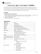
Table 2-1 - Pinout Specification for UART Port [J6]
UART Signal
Connector Pin
GND
1
5V
2
5V
3
Device_RX_Data
4
5V
5
Device_TX_Data
6
Not connected
7 (no pin present)
Not connected
8 (no pin present)
GND
9
EARTH GND
10
Figure 2-2 - DynaWave J6 Pin 1 Location

2 - Electrical Integration
DynaWave| OEM Contactless NFC Module | Installation and Operation Manual
Page 20 of 38 (D998200265-12)
The 5V pins and GND (digital ground) pins must be connected across the terminals of a power supply.
For optimal performance, use a 5VDC ±5% power supply with a current capacity of 500mA or greater.
The worst-case ripple voltage at the power supply’s 5VDC output must not exceed 100mV RMS.
When powered through the UART port, the device draws a maximum of 350mA in steady state.
Solutions should build in a safety margin that anticipates potential peaks up to 500mA.
MagTek recommends 22AWG wires for all signal and power lines. The connector contacts must have a
minimum of 15µ" of selective gold plating over nickel.
MagTek recommends enclosing all wires in a shielded earth-grounded jacket, and a maximum length for
the combination UART/power cable of 32 feet (10 meters). Actual cable length may vary based on cable
material and environmental factors. See Figure 2-3 for an example cable design. See Table 1-1 on page
13 for a list of available cables and accessories MagTek has tested with the device. See section 3.6 for
further information about cabling.
The communication settings for the UART port are shown in Table 2-2. The host must begin
communication using existing device settings, then can use that connection (or the USB Device Port
[J3]) to reconfigure the port settings. Programmers should see section 7 Developing Host Software for
cross-references to programming tools and documentation for communicating through this port and
configuring the device.
Table 2-2 - UART Communication Settings
Parameter
Value / Default
Signal Voltage
3.3V (TTL)
Transmission Protocol
Asynchronous
Duplex
Full
Data Length
8 bits (Bit 7: MSB, Bit 0: LSB)
Parity
None
Start bits
1 bit
Stop bits
1 bit
Flow Control
None
Transmission Speed (baud rate)
115200 baud
/